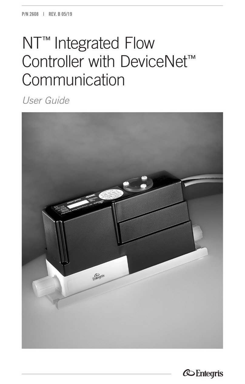
entegris NT6500 User manual

P/N 1223 | REV. J 08/20
NT™
Integrated Flow
Controller, Model 6500
User Guide


Table of Contents
Introduction .................................. 2
Identifying Non-standard
Product Configurations ............ 2
Principle of Operation .............. 2
System Block Diagram ............. 2
Factory Configured ................... 3
Continuous vs
Batch Control ............................. 3
Suspend Control Feature ......... 3
General Considerations .............. 4
Line Pressure .............................. 4
Pressure Drop.............................. 4
Power Supply Requirements ... 4
Dimensions ................................. 6
Installation ..................................... 8
Provided Equipment ................. 8
Mounting Requirements .......... 9
Mechanical Installation .......... 10
Proper Installation and
Operation with On/Off
Valves ......................................... 11
Electrical Connections ........... 12
Wire Connections .................... 13
Wiring Diagram ........................ 14
Optional Connections ............ 15
Setpoint Signal Setup .............. 16
Calibration Graphs .................. 17
Unit Operation ............................ 18
Operating Environment ......... 18
Performance ............................. 18
Diagnostic Guide ........................ 20
Maintenance ................................ 22
Normal Operation ................... 22
Re-zero Function .................... 22
Proper Installation and
Operation with On/Off
Valves ......................................... 23
Reference ..................................... 24
Physical specifications ............ 24
Electrical specifications .......... 24
Performance specifications .. 25
Ordering Information ................ 25
Certifications ............................... 27
CE Compliance ........................ 27
Repair and Warranty Service .. 27
Technical Support ................... 27
For More Information ............. 27
Terms and Conditions ............ 27
Limited Warranty ..................... 27
NT INTEGRATED FLOW CONTROLLER, MODEL 6500
1Entegris, Inc. | User Guide

Introduction
This manual is for use with standard
NT
™
Integrated Flow Controllers,
Model 6500. These instruments have
been designed for use in high-purity
applications in the semiconductor
industry. The wetted parts are
constructed with PTFE, PFA or other
similar high-purity inert materials.
WARNING! Attempting to install
or operate standard NT Integrated
Flow Controller, Model 6500
without reviewing the instructions
contained in this manual could
result in personal injury or
equipment damage.
IDENTIFYING NON-STANDARD
PRODUCT CONFIGURATIONS
—
This User’s Guide applies to product
manufactured as the standard NT
Integrated Flow Controller, Model
6500. Entegris also manufactures
nonstandard product to meet the
needs of specific applications.
Non-standard product may have
dierent materials of construction,
accuracy specifications, performance
and other specifications that
dierentiate the non-standard
product from the standard oering.
NOTE: Nonstandard NT Integrated
Flow Controller, Model 6500 may be
identified by the model number found
on the product label. Specifications
for nonstandard NT Integrated Flow
Controller, Model 6500 are available
by contacting Entegris.
Nonstandard NT Integrated Flow
Controllers, Model 6500 product line,
are identified with an “M” followed
by a number code.
Example part number:
6500-T2-F03-B06-A-P7-U3-M02
The “M02” designates the product
as a nonstandard product manu-
factured to certain specifications
designated under the “M02” code.
PRINCIPLE OF OPERATION
—
The user provides a setpoint signal
that corresponds to the desired
amount of flow. The standard NT
Integrated Flow Controller, Model
6500 compares the setpoint to the
actual flow signal from the flow
module. If the actual flow is greater
than the setpoint, the unit closes the
valve. If the actual flow is less than
the setpoint, the unit opens the valve.
The flow controller does this in
a precise manner until the actual
flow signal is equal to the setpoint.
NT Integrated Flow Controller, Model 6500
control interface
Flow module Valve module
Fluid flow
Fluid flow
Setpoint
Valve
control
Power
Flow
signal
Fluid flow
Inlet
pressure
signal
Flow, pressure
measurement
NT INTEGRATED FLOW CONTROLLER, MODEL 6500
2User Guide | Entegris, Inc.

FACTORY CONFIGURED
—
The standard NT Integrated Flow
Controller, Model 6500 is pre-
configured from the factory for the
flow range specified by the user.
The specified flow range is found on
the label of the unit. The unit control
algorithm uses pressure and flow
measurements to ensure proper
operation within specification.
CONTINUOUS VERSUS
BATCH CONTROL
—
The standard NT Integrated Flow
Controller, Model 6500 may be
ordered as a continuous type
controller or a batch type controller.
Refer to page 25 for part number
information.
The continuous controller type is
for applications requiring continuous
flow rate control, where the valve
module is never required to fully
close.
The batch controller type is for
applications that require the valve
module to fully close between batch
dispense cycles. The batch controller
will form a leak-tight seal from 414 kPa
(0 to 60 psig) inlet pressure.
SUSPEND CONTROL FEATURE
—
CONTINUOUS controller type only:
The unit functions will be suspended
when the setpoint is below 5% of
the full scale range. The unit valve
position is locked when the control
is suspended. Locking the valve
position allows the unit to reach
the desired flow faster when the
setpoint is reactivated.
Controller
type CONTINUOUS BATCH
Input
type
A (4–20 mA)
B (0–10 VDC)
C (0–5 VDC)
K (4–20 mA)
L (0–10 VDC)
M (0–5 VDC)
NT INTEGRATED FLOW CONTROLLER, MODEL 6500
3Entegris, Inc. | User Guide

General Considerations
NOTE: The flow controller has been
factory sealed. Do not attempt to
remove the cover of the unit. Any
attempt at removal of the unit cover
will void the warranty.
LINE PRESSURE
—
The system line pressure (measured at
the inlet of the unit) must be between
69 to 414 kPa (10 to 60 psig). The
minimum operating pressure is
69 kPa (10 psig).
PRESSURE DROP
—
The minimum operating pressure
is 69 kPa (10 psig). The minimum
pressure drop (dierential pressure)
required for the unit is 69 kPa (10 psid).
For example, if the flow controller
is operating at an inlet pressure of
103 kPa (15 psig) and outputs the flow
to a pressurized canister, which is
pressurized to 69 kPa (10 psig), the
pressure available to the unit will be
5 psid (103 kPa [15 psig] inlet pressure
minus 69 kPa [10 psig] canister
pressure). This scenario does not
meet the pressure drop requirement
of 69 kPa (10 psid) and the unit may
not perform within specification. For
this example, either increase the inlet
pressure or decrease the canister
pressure to obtain a 69 kPa (10 psid)
pressure drop.
POWER SUPPLY REQUIREMENTS
—
The power supply range for the
standard NT Integrated Flow Control-
ler, Model 6500 is 24 VDC ±10%.
The power supply to the flow con-
troller must provide clean power to
the unit and must be used only to
power similar measurement-type
devices. The power supply must not
be used to power other inductive
loads, such as motors, relays or sole-
noids. These devices may produce
electrical transients that may aect
unit measurements. An induced
power spike, creating an interruption
in power greater than 10 msec in
duration, may cause the unit to reset.
In addition to providing clean power,
the instrumentation signals and
power return lines must not be run
within the same conduit or cable
along with heavy current demands
from motors, charging capacitors
or other inductive loads. This may
cause a voltage change within the
instrumentation signal line, causing
erroneous output readings from the
flow controller. Loss of power will not
cause the loss of any system parame-
ters or calibration values.
Supply Current
The power supply must provide
continuous 1.0 ADC service for
each flow controller installed.
NT INTEGRATED FLOW CONTROLLER, MODEL 6500
4User Guide | Entegris, Inc.

Input Impedance of the
Voltage Setpoint
The input impedance of the voltage
setpoint is 20 kOhm.
Voltage Drop at the 4–20 mA
Setpoint Input
The 4–20 mA input will drop 2.5 volts
at 20 mA. Input impedance is 125 ohms.
Lift-o Voltage of the 4–20 mA
Output Loops
The minimum lift-o voltage of the
4–20 mA output loops (flow, pres-
sure measurements) is 12 VDC. The
minimum lift-o voltage is the volt-
age required at the unit for proper
operation. The maximum load
resistance for a 24 VDC supply is
600 ohms and includes the resistance
of measurement devices and the
interconnecting cable.
Output Load Resistance Eects
Using a 24 VDC power supply, the
two 4–20 mA output loops (flow and
pressure) will experience no shift if
the load resistance is 0–600 ohms.
Reverse Polarity Protection
The flow controller is reverse polarity
protected; connecting the 24 VDC
power to the incorrect positive and
ground wires will not harm the unit.
To operate properly, the polarity must
be correct.
Over-Voltage on any Wire (DC)
The flow controller will withstand
the continuous application of 30 VDC
on any wire without compromising
the unit.
Over-Voltage on any Wire (AC)
The flow controller is not designed to
withstand the accidental application
110/220 VAC to any wire. Application
of AC voltage will damage the unit.
Short Protection
The flow controller will not be
damaged or compromised in any
way if any combination of wires
are shorted together.
Circuit Protection
Fuse the three input power lines to
each individual NT Integrated Flow
Controller, Model 6500. The three
lines are:
• 2-Red/Pin R, +24 VDC (main
power, 1.0 Amp nominal)
• 3-Orange/Pin M, Flow output,
+24 VDC supply
• 4-Yellow/Pin T, Pressure output,
+24 VDC supply
Use a 2 Amp rated, time lag fuse. A
single fuse can be used for all three
input power lines combined, or in-
dividually, as preferred. Place the
fusing on the input power lines to
the unit at the equipment electrical
enclosure to ensure that both the
wiring to the unit and the unit itself
are protected from any over-current
condition. Best practice is to locate
the fuse away from the typical liquid
exposure or harmful vapor areas.
Locating it within the electrical
enclosure shared by the power
supply enables accessibility for
troubleshooting or replacement.
NOTE: Do not power down the unit
until the homing cycle is complete.
NT INTEGRATED FLOW CONTROLLER, MODEL 6500
5Entegris, Inc. | User Guide

DIMENSIONS
—
Top View
197.6 mm (7.78")
216.7 mm (8.53")
229.9 mm (9.05")
B
72.9 mm
(2.87")
7.1 mm
(0.28")
47.0 mm
(1.85")
65.5 mm
(2.58")
End View
NT INTEGRATED FLOW CONTROLLER, MODEL 6500
6User Guide | Entegris, Inc.

DIMENSIONS (CONTINUED)
—
Ø6.1 mm
(0.24")
76.2 mm
(3.00")
Cable connector
(12DXX)
D-series Electrical Connector
Side View (Pigtail Electrical Cable Shown)
76.2 mm
(3.00")
12 conductor
FEP-jacketed cable
Flared nut (2) C
A
Ø6.4 mm
(0.25")
FITTING A A* B C
⁄"
F02
123.4 mm
(4.86")
130.0 mm
(5.12")
244.1 mm
(9.61")
19.6 mm
(0.77")
⁄"
F03
123.4 mm
(4.86")
130.0 mm
(5.12")
247.7 mm
(9.75")
19.6 mm
(0.77")
⁄"
F04
127.0 mm
(5.00")
133.6 mm
(5.26")
251.7 mm
(9.91")
21.6 mm
(0.85")
⁄"
F06
134.9 mm
(5.31")
141.5 mm
(5.57")
257.8 mm
(10.15")
25.7 mm
(1.01")
*IFC with DeviceNet communication
NT INTEGRATED FLOW CONTROLLER, MODEL 6500
7Entegris, Inc. | User Guide

Installation
PROVIDED EQUIPMENT
—
Remove Unit from the Bag
Optional
NOTE: This unit has been assembled
and double-bagged under cleanroom
conditions. To maintain purity, only
open under cleanroom conditions.
CAUTION!
Do not tighten the nuts that protect the flared tube
connections during shipment. (See Prepare Fluid Lines
on page 10). Tightening these nuts without the proper
tubing installed may damage the unit’s flared tube
onnections.
Gloves
NT INTEGRATED FLOW CONTROLLER, MODEL 6500
8User Guide | Entegris, Inc.

FLOW DIRECTION
8.53˝ (216.7 mm)
1.85˝
(4
7.
0 mm)
Mount the Unit
The flow controller and base
bracket assembly must be
mounted to a solid surface
to ensure stability. Verify the
valve and the electrical cable
are free from mechanical stress
from the surrounding equipment.
NOTE: The flow controller
requires mounting in the
direction of the fluid flow.
Recommended
Hardware
#10 (M4)
Pan head
#10 (M4)
Flat washer
MOUNTING REQUIREMENTS
—
The flow controller may be mounted
in any orientation. The unit does not
require straight lengths of tubing at
the inlet or the outlet connection.
NT INTEGRATED FLOW CONTROLLER, MODEL 6500
9Entegris, Inc. | User Guide

MECHANICAL INSTALLATION
—
The standard NT Integrated Flow
Controller, Model 6500 must be
used with the proper tubing size
and fittings.
To prepare the fluid lines, begin by
sliding the supplied nuts onto the
fluid tube.
CAUTION! Over-tightening of
the nuts will result in damage
to the fitting.
NOTE: Flare each tube end prior to
installation onto the valve fitting.
FLOW DIRECTION
Connect Fluid Lines
Flare each tube end
prior to installation
FLOW DIRECTION
Prepare Fluid Lines
Process fluid tube
Process fluid tube
Slide the nut onto the tube
NT INTEGRATED FLOW CONTROLLER, MODEL 6500
10 User Guide | Entegris, Inc.

When installing flared tubing to the
flow controller, the flared tube is
pushed over the valve’s fitting until
the fitting reaches the smaller tube
diameter. The amount of torque
required to tighten the nut is depen-
dent upon the size of the fitting.
FITTING SIZE 11⁄44"33⁄88"11⁄22"33⁄44"
Torque (in•lbs) 5 8 11 14
Torque (N•m) 0.56 0.90 1.24 1.58
Care should be taken when installing
the flow controller to avoid fluid
leaks. Do not use excessive torque
or subject the unit to high heat during
installation. The unit and base bracket
assembly must be mounted to a solid
surface to ensure stability. Verify the
body and the electrical cable are free
from mechanical stress from the
surrounding equipment.
PROPER INSTALLATION AND
OPERATION WITH ON/OFF VALVES
—
The NT Integrated Flow Controller,
Model 6500 often is installed
between upstream and/or down-
stream on/o valves. However,
precautions must be taken during
the re-zero function to ensure
proper operation of the flow con-
troller with the on/o valves.
The valve module in the flow controller
will close under two conditions:
1. Manual re-zero using the green
wire (see the Maintenance Section
on p. 22).
2. When zero flow is requested while
using a BATCH unit.
If the flow controller closes while
either the upstream or downstream
valve is closed, this will cause
pressure to increase above 414 kPa
(60 psig) due to compression of the
volume of “trapped” fluid in the flow
controller. The subsequent pressure
increase inside the flow controller
can lead to inaccurate re-zeroing,
and possible unit damage. Thus, the
NT Integrated Flow Controller, Model
6500 should NEVER be closed when
an upstream on/o valve is closed.
To address this issue, one possible
solution is to keep the on/o valves
upstream and downstream of the
flow controller open at all times. If
this is not possible, the flow controller
should be closed first, allowing
adequate time before either the
upstream or downstream valves
are closed.
Installation and Operation Example with Two On/O Valves
Flow directionFlow direction
Valve #1 Valve #2
NT Integrated Flow Controller, Model 6500
NT INTEGRATED FLOW CONTROLLER, MODEL 6500
11Entegris, Inc. | User Guide

ELECTRICAL CONNECTIONS
—
Pigtail Electrical Cable
Units specified with a Pigtail electrical
connection are manufactured with a
permanently attached FEP-jacketed
cable.
D-Series Electrical Connector
The connector and mounting recep-
tacle of the D-series connector are
constructed of polypropylene. The
connector is over-molded onto an
electrically shielded, PVC-jacketed
cable. The mounting receptacle uses
a Viton®gasket seal at the mounting
panel. The pin contacts for the
electrical connection are gold
plated for performance and
corrosion resistance.
Connect D-series Electrical Cable
to Unit
The D-series electrical connector is
physically “keyed” in two locations,
making it impossible to insert the
connector improperly. White markings
are also printed onto the connector
to visually align the connector into
the correct position. Pressing it into
the mounting receptacle locks the
connector in place. To remove the
connector, rotate the coupling ring
in the direction of the printed white
arrow.
Align white marks
Electrical cable
Snap
NT INTEGRATED FLOW CONTROLLER, MODEL 6500
12 User Guide | Entegris, Inc.

WIRE CONNECTIONS
—
The following Pin Diagram details
the wire connections for the flow
controller electrical cable:
Table: Pin DIAGRAM
PIN NO. COLOR FUNCTION
01 Brown Pressure, 4–20 mA
02 Red +24 VDC
03 Orange Flow, +24 VDC
04 Yellow Pressure, +24 VDC
05 Blue Flow, 4–20 mA
06 Violet Factory Use Only
07 White Factory Use Only
08 Black Ground
09 Green Re-zero
10 Tan Setpoint, 4–20 mA
11 Pink Setpoint, Voltage
12 Gray Setpoint, Com
Mandatory Connections
Pin 02 (red) and pin 08 (black) must
be connected according to the Pin
Diagram Table. The setpoint must also
be connected, pin 10 (tan, 4–20 mA
setpoint) and pin 12 (gray, com setpoint);
or to pins 11 (pink, voltage setpoint)
and 12 (gray, com setpoint). To ensure
proper operation, there must be a
low impedance connection between
pin 08 (black, ground) and pin 12
(gray, Com setpoint). Further, if the
setpoint input is 4–20 mA, the setpoint
control signal must be from a source
type, not a sink type. Consult Entegris
with any questions about electrical
installation. See the Wiring Diagram
on page 14.
To perform a periodic re-zero,
connect pin 09 (green) as indicated
in the Wiring Diagram on page 14.
DO NOT CONNECT CONTINUOUS
VOLTAGE to this pin. If continuous is
applied, the flow controller valve will
remain in a closed position. Only
apply voltage when the re-zero
function is required.
Unused Connections
Pin 06 (violet) and pin 07 (white) are
for factory use only. Do not connect
to power supply or ground. These
wires must remain disconnected.
Plug Orientation
Front View
10
08
07
11
06
05
09
01
02
04
03
12
NT INTEGRATED FLOW CONTROLLER, MODEL 6500
13Entegris, Inc. | User Guide

WIRING DIAGRAM
—
Power supply
24 VDC
±10%
Electrical cable
09-Green
Normally open switch
For
re-zeroing
Setpoint control signal
4–20 mA
02-Red (+)
08-Black (-)
Low impedance
common connection
12-Gray (-)
10-Tan (+)
Power supply
24 VDC
±10%
Electrical cable
09-Green
Normally open switch
For
re-zeroing
Setpoint control signal
0–5 VDC
or
0–10 VDC
02-Red (+)
08-Black (-)
Low impedance
common connection
12-Gray (-)
11-Pink (+)
OR
NT INTEGRATED FLOW CONTROLLER, MODEL 6500
14 User Guide | Entegris, Inc.

OPTIONAL CONNECTIONS
—
To monitor flow rate, apply +24 VDC
to pin 03 (orange) and measure the
4–20 mA flow output signal from pin
05 (blue).
To monitor inlet pressure, apply 24
VDC to pin 04 (yellow) and measure
the 4–20 mA pressure output signal
from pin 01 (brown).
The outputs are optically isolated.
Using a separate power supply is
possible.
Power supply
24 VDC ±10%
Flow display/
measurement device
Pressure display/
measurement device
03-Orange
flow loop
04-Yellow
pressure loop
05-Blue
01-Brown
Electrical cable
NT INTEGRATED FLOW CONTROLLER, MODEL 6500
15Entegris, Inc. | User Guide

SETPOINT SIGNAL SETUP
—
Use the following formulas to adjust
your setpoint signal output device
to match the flow range of the unit.
Repeat the calculations for multiple
control points.
6500-T4-F03-D06-A-P7-U3
9999
⁄" Flared
0-1250 mL/min
Flow Range = 0 -1250 mL/min
Product Label
4 mA or
0 VDC
at 0 mL/min
20 mA or
5 or 10 VDC
at 1250 mL/min
Span = Range of the
output signal
FS = Full scale flow
(mL/min/L/min)
F = Desired flow
(mL/min/L/min)
4–20 mA Setpoint Control Signal
+ 4 mA
Setpoint =
mA
Range of Product =0-1250 mL/min
F =125 mL/min
Span =20 mA
-
4 mA = 16 mA
FS =1250 mL/min
(1250 mL/min)
5.6 mA
+ 4 m
A
Setpoint
mA
Setpoint
mA
=
=
0–5 VDC or 0 –10 VDC Setpoint Control Signal
Setpoint =
VDC
Range of Product = 0-1250 mL/min
F =500 mL/min
Span =10 VDC
-
0 VDC = 10 VDC
FS =1250 mL/min
(1250 mL/min)
4.0 VDC
Setpoint
VDC
Setpoint
VDC
=
=
(125 mL/min) × (16 mA)
(500 mL/min) × (10 VDC)
F × Span
FS
F × Span
FS
Formulas and Example Calculations
NT INTEGRATED FLOW CONTROLLER, MODEL 6500
16 User Guide | Entegris, Inc.

CALIBRATION GRAPHS
—
NOTE: Specifications are subject to
change without notice. Please consult
the factory for the most current
information.
0%
0
4
8
12
16
20
24
20% 40% 60%
Percent of Full Scale Flow
mA Output
80% 100%
120%
mA Output vs. Full Scale Flow
21.75
20
5.6
Output not specified
below 5.6 mA (10% FS flow)
mA output values
indicated on graph
0
4
8
12
16
20
24
0510 15 20 25 30 35 40 45 50 55 60 65
70
mA Output vs. Pressure
21.75
20
4
DO NOT OPERATE
BELOW 0 psig
DO NOT OPERATE
ABOVE 60 psig (414 kPa)
mA output values
indicated on graph
Pressure (psi
g
)
mA Output
NT INTEGRATED FLOW CONTROLLER, MODEL 6500
17Entegris, Inc. | User Guide

Unit Operation
OPERATING ENVIRONMENT
—
Operating Temperature
The flow controller is designed to
operate in ambient temperature,
cleanroom environments. The unit is
specified to operate at temperatures
between 10° and 65°C (50° and 149°F).
PFA sensor isolators are recommended
for process temperatures above 40°C
(104°F). Contact the factory recom-
mended materials of construction for
applications involving hydrofluoric
acid (HF) with temperatures above
30°C (86°F).
When the process fluid is above
ambient temperatures 23°C (73°F),
the system will experience slight
accuracy errors due to instrument
warm-up and changes in viscosity
and specific gravity of the liquid. The
unit must be re-zeroed after any
temperature change. Please see the
Maintenance Section on page 22 to
perform the re-zero.
Eects of Fluid Viscosity and
Specific Gravity
The flow controller has been factory
calibrated using deionized water.
Fluids with viscosities and/or specific
gravity dierent from the calibration
fluid (water) will cause slight accuracy
errors. Correction factors for viscosity
and specific gravity changes may be
obtained from Entegris by calling or
following the sensing and control
product links at www.entegris.com.
Storage Temperature
The flow controller will withstand
storage temperatures between
-15° and 40°C (5° and 104°F) with
no permanent eect on the perfor-
mance of the device.
Unit Enclosure
The standard NT Integrated Flow
Controller, Model 6500 cover is
factory sealed and should not be
tampered with or opened. Spray-
down or temporary immersion will
not compromise the performance
of the unit.
NOTE: Any attempt to remove, tamper
or open the flow controller cover will
void the warranty.
PERFORMANCE
—
Operating Pressure Requirements
The flow rate is calculated using
Entegris’ dierential pressure flow
technology. The minimum operating
pressure is 69 kPa (10 psig). The
minimum pressure drop (dierential
pressure) required for the flow
controller is 69 kPa (10 psid).
CAUTION! The flow controller may
be damaged if it is subjected to any
level of vacuum pressure (less than
atmospheric pressure).
NOTE: To perform within specifica-
tion, the available inlet pressure
must be 69 kPa (10 psid) greater
than the outlet pressure (69 kPa
[10 psid] dierential pressure).
NT INTEGRATED FLOW CONTROLLER, MODEL 6500
18 User Guide | Entegris, Inc.
Other manuals for NT6500
1
Table of contents
Other entegris Controllers manuals
