manuals.online logo
Brands
  1. Home
  2. •
  3. Brands
  4. •
  5. Enterasys
  6. •
  7. Switch
  8. •
  9. Enterasys G3G124-24 User manual

Enterasys G3G124-24 User manual

How to Use This Guide
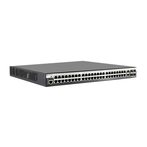
UsethisguidetosetupyourEnterasys®G‐Seriesswitch(pictured
below)andoptionalcomponents.Forcompleteinstructions,seethe
EnterasysG‐SeriesHardwareInstallationGuide.
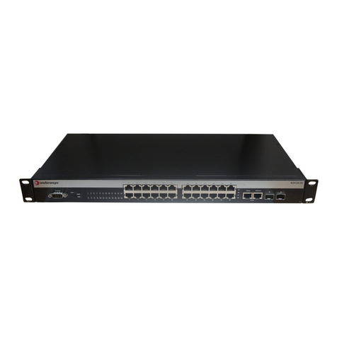
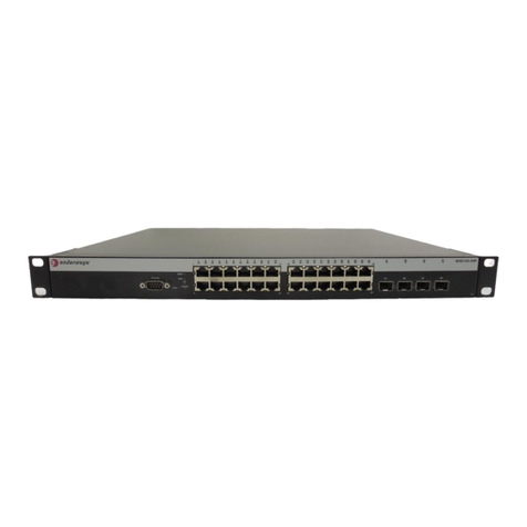
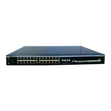
Figure 1 G-Series Ethernet Switch (G3G124-24 Displayed)
Handling the G3 Switch and Components
Unpacking the Switch or Components
Unpacktheswitchasfollows:
1. Removethepackingmaterialprotectingtheswitch.
2. Removetheswitchorcomponentfromthenon‐conductivebag.
3. Performavisualinspectionoftheswitchforanysignsof
physicaldamage.ContactEnterasysNetworksifthereareany
signsofdamage.See“GettingHelp”formoreinformation.
Installing the Optional PoE module into an IOM Card
IfyouhavepurchasedanoptionalPoEmodule(G3G‐POE),you
caninstallitbeforeinstallingtheG3G‐24TXIOMcardintothe
G‐Seriesbasesystemchassisoratanytimebyfirstremovingthe
IOMcardasdescribedin“RemovinganIOMCard”.
ToinstallthePoEmoduleinanIOMcard:
1. GentlyplugthePoEmoduleintotheIOMcardbyfittingthe
standoffsintothePoEboardmountingholesasshownin
Figure 2.Thereshouldbeadirectverticaltranslationof
standoffstoPoEmountingholes.
2. UsingthescrewsshippedwiththePoEmodule,firmlyattach
thePoEmoduletotheIOMcard.
Figure 2 Installing a PoE Module in the G3G-24TX
1USB Console Port 4Optional IOM Card Slot 2
2Optional IOM Card Slot 3 5Fixed Switch Ports
3Optional IOM Card Slot 4 6RJ45 Console Port
Electrical Hazard: Only qualified personnel should perform
installation procedures.
Caution: The switch can be damaged by electrostatic discharge.
Attach an ESD wrist strap before handling the switch or
components.
1Fastening screws 4PoE Module’s IOM card connector
2PoE daughter card module 5G3G-24TX IOM card (motherboard)
3IOM card’s PoE connector
Installing an IOM Card
ToinstallanIOMcard:
1. Loosenthecaptivescrewsonthecoverplateandremovethe
coverplatefromtheslot.
2. InserttheIOMcardintheguiderailoftheslot.Gentlyslidethe
cardintotheslot,asshowninFigure 3,untiltheIOMcard
engagestheconnectoronthebackplaneandtheIOMcardlocks
intoplaceandisflushwithadjoiningcoverplates.
3. Tightenthetwocaptivescrews.
Figure 3 Installing the IOM card (G3G-24TX with optional PoE shown)
4. Ifinstallingadditionalmodules,waituntiltheslotstatusLED
forthepreviouslyinstalledIOMissolidgreenbeforeinstalling
additionalmodules.Savecoverplatesforoptionalfutureuse.
5. Aftercompletingallmoduleinstallation,besuretoinstall
coverplate(s)overanyunusedIOMslot(s)tocontainEMI
radiationandensureproperaircirculation.
Removing an IOM Card
1. DisconnectanycablingfromtheIOMcard.
2. LoosentheIOMcard’stwocaptivescrews.
3. Pressthepoweroffbuttoncorrespondingtotheslotfromwhich
youwanttoremovetheIOMcardasshowninFigure 4.
Figure 4 Chassis LEDs
4. Whentheslot’sPOWEROFFstatusLEDturnsamber,gently
slidethemoduleoutoftheslot.
Caution: If you are installing multiple IOMs into a switch that is
running, wait until the previously installed IOM is completely
initialized before attempting to install the next IOM. Initialization is
complete when the slot’s status LED turns solid green.
1IOM slot 2 4Optional G3G-POE module
2IOM handle 5IOM
3Captive screw
Caution: Do not attempt to power-down and remove more than one
IOM at a time. You must complete the removal procedure outlined in
this section before attempting to remove another IOM.
1Power Supply LEDs 3IOM power off buttons (Slot 2, 3 and 4)
2SYSTEM LED 4IOM power off status LEDs (Slot 2, 3 and 4)
Replacetheslot’scoverplatetocontainEMIradiationandensure
properaircirculation.
Installing a Power Supply
ThesepowersuppliescanbeinstalledontheG‐Seriesswitch:
•G3‐PWR,a400‐wattACpowersupply(requires15Acircuit)
•G3‐PWR‐POE,a1200‐wattACpowersupply(requires20A
circuit)
ToinstallasinglepowersupplyintheG‐Seriesswitch:
1. Holdingthepowersupplybyitshandle,positionitwiththe
statusLEDstotheleftandalignitwiththeslotopening.
2. Carefullyslidethemoduleuntilitconnectstothebackplane.If
significantresistanceisencounteredbeforethepowersupplyis
seated,removeandreinsertit.Donotforcethemoduleinto
place.
3. Securethepowersupplytothechassisbytighteningthecaptive
screws.
4. IfyouarefinishedinstallingIOMcardsandarereadytoconnect
toapowersource,plugthepowercordintothepowersupply
ACinlet,thenintoagroundedoutlet.
Completing the Setup and Downloading the Latest
Firmware
OnceyouhaveconnectedpowertotheG3switchandverifiedLED
activity,youcancompletethesetupprocess.Formoreinformation,
seetheEnterasysG‐SeriesHardwareInstallationGuide.
1. DeterminethelatestG3firmwareversionat:
http://secure.enterasys.com/services/support/downloads/software
2. Connecttheswitchtothenetwork.
3. Connectamanagementstationtotheconsoleport.
4. Verifythatthenetworkdevicesconnectedtotheswitchportsare
poweredon,andthateachlink/activityLEDison(solidgreenor
blinkinggreen).
5. Atthedeviceconnectedtotheconsoleport:
a. EnteradminforUsername.
b. AtthePasswordprompt,pressENTER(RETURN).
c. Atthecommandprompt,determineifthelatestfirmwareimage
isloadedontheswitchbyenteringthiscommand:
show version
d.Iftheoutput(underFWVers i on )displaysanolderversion
numberthanthatdeterminedinStep1,downloadandactivate
thenewversionasdirectedonthedownloadwebsiteorusethe
CLIcommandslistedinTable 1.)
Basic Setup Commands
Table 1listsCLIcommandsthatarerequiredforsettinguptheG3
switchwiththelatestfirmware.Table 2listsadditionalconfiguration
commandsforyourG3switch.ForthecompletelistofCLI
commands,seetheEnterasysG‐SeriesCLIReference.
Caution: Use caution when removing an IOM on which you have an
optional PoE module installed to avoid damaging the PoE module.
Note: The following procedure is for installing a single power supply.
For instructions on installing a second power supply, power supply
planning considerations, and advanced power configurations, see
the G‐SeriesHardwareInstallationGuide.
Table 1 Required CLI Setup Commands
Step Ta s k CLI commands
1Set a new password set password [username]
2Set the switch IP address set ip address ip-address [mask
ip-mask] [gateway ip-gateway]
3Download, activate, and
verify new firmware on the
switch using TFTP copy.
copy tftp://tftp_svr_ip_addr/
filename system:image
set boot system filename
show version
Specifications
Foracompletelistofspecifications,seetheEnterasysG‐Series
HardwareInstallationGuide.
Interfaces
Switch Dimensions
Size:8.8Hx44.1Wx48.1D(cm)
Power Supply Input Voltage
G3‐PWR:100to240VAC/6A
G3‐PWR‐POE:100‐125VAC/12Ato200‐240VAC/7A
Temperature and Humidity
Operating:0ºCto50ºC
Storage:‐40ºCto+70ºC
Operatingrelativehumidity:5%to95%(non‐condensing)
Table 2 Optional CLI Setup Commands
Task CLI commands
Save the active configuration save config
Enable or disable SSH set ssh enable | disable
Enable or disable Telnet set telnet {enable | disable}
[inbound | outbound | all]
Enable or disable HTTP
management (WebView)
set webview {enable | disable}
Enable or disable SNMP port link
traps
set port trap port-string
{enable | disable}
Set the per port broadcast limit set port broadcast port-string
threshold-value
Configure a VLAN set vlan create vlan-id
set port vlan port-string
vlan-id modify-egress
Set a Syslog server IP and severity set logging server index ip-addr
ip-addr severity severity state
enable
Configure and enable a RADIUS
server.
set radius server index ip-addr
port [secret-value]{realm
{management-access | any |
network-access}
set radius enable
Note: The 10BASE-T/100BASE-TX/1000BASE-T ports on the
G3G124-24Psupport 802.3af PoE connections out-of-box. The
10BASE-T/100BASE-TX/1000BASE-T ports on the G3G124-24
and G3G-24TX IOM card can support 802.3af PoE connections
by installing the optional G3G-POE module.
G3G124-24 • 24 10BASE-T/100BASE-TX/1000BASE-T ports
• Two combo 1000BASE-SX, 1000BASE-LX,
100BASE-FX, or 1000BASE-TX SFP ports
G3G124-24P • 24 10BASE-T/100BASE-TX/1000BASE-T 802.3af PoE
ports
• Two combo 1000BASE-SX, 1000BASE-LX,
100BASE-FX, or 1000BASE-TX SFP ports
G3G170-24 • 24 1000BASE-SX, 1000BASE-LX, 100BASE-FX, or
1000BASE-TX SFP ports
G3G-24TX • 24 10BASE-T/100BASE-TX/1000BASE-T ports
• Two combo 1000BASE-SX, 1000BASE-LX,
100BASE-FX, or 1000BASE-TX SFP ports
G3G-POE • Add-on PoE module for G3G124-24 switch and
G3G-24TX IOM
G3G-24SFP • 24 1000BASE-SX, 1000BASE-LX, 100BBASE-FX,
1000BASE-TX SFP ports
G3K-2XFP • Two 10-Gigabit Small Form Factor Pluggable (XFP)
interfaces
G3K-4XFP • Four 10-Gigabit Small Form Factor Pluggable (XFP)
interfaces
Getting Help
Related Documents
Thelatestdocumentationislocatedonlineatwww.enterasys.com/support/manuals.
Notice
Enterasys Networksreservestherighttomakechangesinspecificationsandotherinformation
containedinthisdocumentanditswebsitewithoutpriornotice.Thereadershouldinallcases
consultEnterasys Networkstodeterminewhetheranysuchchangeshavebeenmade.
Thehardware,firmware,orsoftwaredescribedinthisdocumentissubjecttochangewithout
notice.
INNOEVENTSHALLENTERASYS NETWORKSBELIABLEFORANYINCIDENTAL,
INDIRECT,SPECIAL,ORCONSEQUENTIALDAMAGESWHATSOEVER(INCLUDINGBUT
NOTLIMITEDTOLOSTPROFITS)ARISINGOUTOFORRELATEDTOTHISDOCUMENT,WEB
SITE,ORTHEINFORMATIONCONTAINEDINTHEM,EVENIFENTERASYS NETWORKSHAS
BEENADVISEDOF,KNEWOF,ORSHOULDHAVEKNOWNOF,THEPOSSIBILITYOFSUCH
DAMAGES.
Enterasys Networks, Inc.
50MinutemanRoad
Andover,MA01810
©2009Enterasys Networks, Inc.Allrightsreserved.
PartNumber: 9034443‐02 February 2009
ENTERASYS,ENTERASYSNETWORKS,ENTERASYSSECURENETWORKS,NETSIGHT,
ENTERASYSNETSIGHT,SECURESTACK,ENTERASYSSECURESTACK,andanylogos
associatedtherewith,aretrademarksorregisteredtrademarksofEnterasysNetworks,Inc.,inthe
UnitedStatesand/orothercountries.ForacompletelistofEnterasystrademarks,see
http://www.enterasys.com/company/trademarks.aspx.
Allotherproductnamesmentionedinthismanualmaybetrademarksorregisteredtrademarksof
theirrespectivecompanies.
Regulatory Compliance Information
Federal Communications Commission (FCC) Notice
ThisdevicecomplieswithPart15oftheFCCrules.Operationissubjecttothefollowingtwo
conditions:(1)thisdevicemaynotcauseharmfulinterference,and(2)thisdevicemustacceptany
interferencereceived,includinginterferencethatmaycauseundesiredoperation.
NOTE: ThisequipmenthasbeentestedandfoundtocomplywiththelimitsforaclassAdigital
device,pursuanttoPart15oftheFCCrules.Theselimitsaredesignedtoprovidereasonable
protectionagainstharmfulinterferencewhentheequipmentisoperatedinacommercial
environment.Thisequipmentuses,generates,andcanradiateradiofrequencyenergyandifnot
installedinaccordancewiththeoperator’smanual,maycauseharmfulinterferencetoradio
communications.Operationofthisequipmentinaresidentialareaislikelytocauseinterferencein
whichcasetheuserwillberequiredtocorrecttheinterferenceathisownexpense.
WARNING: Changesormodificationsmadetothisdevicewhicharenotexpresslyapprovedby
thepartyresponsibleforcompliancecouldvoidtheuser’sauthoritytooperatetheequipment.
Industry Canada Notice
ThisdigitalapparatusdoesnotexceedtheclassAlimitsforradionoiseemissionsfromdigital
apparatussetoutintheRadioInterferenceRegulationsoftheCanadianDepartmentof
Communications.
Leprésentappareilnumériquen’émetpasdebruitsradioélectriquesdépassantleslimites
applicablesauxappareilsnumériquesdelaclassAprescritesdansleRèglementsurlebrouillage
radioélectriqueédictéparleministèredesCommunicationsduCanada.
Class A ITE Notice
WARNING: ThisisaClassAproduct.Inadomesticenvironmentthisproductmaycauseradio
interferenceinwhichcasetheusermayberequiredtotakeadequatemeasures.
Clase A. Aviso de ITE
ADVERTENCIA:EsteesunproductodeClaseA.Enunambientedomésticoesteproductopuede
causarinterferenciaderadioencuyocasopuedeserrequeridotomarmedidasadecuadas.
Klasse A ITE Anmerkung
WARNHINWEIS:DiesesProduktzähltzurKlasseA(Industriebereich).InWohnbereichenkann
eshierdurchzuFunkstörungenkommen,dahersolltenangemesseneVorkehrungenzumSchutz
getroffenwerden.
VCCI Notice
ThisisaclassAproductbasedonthestandardoftheVoluntaryControlCouncilforInterferenceby
InformationTec hnologyEquipment(VCCI).Ifthisequipmentisusedinadomesticenvironment,
radiodisturbancemayarise.Whensuchtroubleoccurs,theusermayberequiredtotakecorrective
actions.
World Wide Web www.enterasys.com/services/support/
Phone 1-800-872-8440 (toll-free in U.S. and Canada)
or 1-978-684-1000
To find the Enterasys Networks Support toll-free
number in your country:
www.enterasys.com/services/support/contact/
Internet mail [email protected]
To expedite your message, type [Switching] in the
subject field of your message.
Latest image and
release notes
www.enterasys.com/services/support/downloads
/software
BSMI EMC Statement — Taiwan
ThisisaclassAproduct.Inadomesticenvironmentthisproductmaycauseradiointerferencein
whichcasetheusermayberequiredtotakeadequatemeasures.
AS/NZS CISPR 22
Hazardous Substances
ThisproductcomplieswiththerequirementsofEuropeanDirective,2002/95/EC,Restrictionof
HazardousSubstances(RoHS)inElectricalandElectronicEquipment.
European Waste Electrical and Electronic Equipment (WEEE) Notice
InaccordancewithDirective2002/96/ECoftheEuropeanParliamentonwasteelectricaland
electronicequipment(WEEE):
1. Thesymbolaboveindicatesthatseparatecollectionofelectricalandelectronicequipmentis
requiredandthatthisproductwasplacedontheEuropeanmarketafterAugust13,2005,the
dateofenforcementforDirective2002/96/EC.
2. Whenthisproducthasreachedtheendofitsserviceablelife,itcannotbedisposedofasunsorted
municipalwaste.Itmustbecollectedandtreatedseparately.
3. IthasbeendeterminedbytheEuropeanParliamentthattherearepotentialnegativeeffectson
theenvironmentandhumanhealthasaresultofthepresenceofhazardoussubstancesin
electricalandelectronicequipment.
4. Itistheusers’responsibilitytoutilizetheavailablecollectionsystemtoensureWEEEisproperly
treated.
Forinformationabouttheavailablecollectionsystem,pleasegoto
www.enterasys.com/services/support/ orcontactEnterasysCustomerSupportat35361705586
(Ireland).
ѻ
ѻક䇈ᯢк䰘ӊ
Supplement to Product Instructions
᳝↦᳝ᆇ⠽䋼៪ܗ㋴(Hazardous Substance)
䚼ӊৡ⿄
(Parts) 䪙
3E
∲
+J
䬝
&G
݁Ӌ䫀
&U
໮⒈㘨㣃
3%%
໮⒈Ѡ㣃䝮
3%'(
䞥ሲ䚼ӊ
(Metal Parts) hƻ ƻ ƻ ƻ ƻ
⬉䏃῵ഫ
(Circuit Modules) hƻ ƻ ƻ ƻ ƻ
⬉㓚ঞ⬉㓚㒘ӊ
(Cables & Cable Assemblies) hƻ ƻ ƻ ƻ ƻ
ล᭭㘮ড়⠽䚼ӊ
(Plastic and Polymeric parts) ƻƻ ƻ ƻ ƻ ƻ
⬉䏃ᓔ݇
(Circuit Breakers) ƻƻ ƻ ƻ ƻ ƻ

ƻ˖ 㸼⼎䆹᳝↦᳝ᆇ⠽䋼೼䆹䚼ӊ᠔᳝ഛ䋼ᴤ᭭Ёⱘ৿䞣ഛ೼ SJ/T 11363-2006 󰵼ޚ㾘ᅮⱘ䰤䞣㽕∖ҹϟDŽ
Indicates that the concentration of the hazardous substance in all homogeneous materials in the parts is
below the relevant threshold of the SJ/T 11363-2006 standard.
h˖ 㸼⼎䆹᳝↦᳝ᆇ⠽䋼㟇ᇥ೼䆹䚼ӊⱘᶤϔഛ䋼ᴤ᭭Ёⱘ৿䞣䍙ߎSJ/T 11363-2006 󰵼ޚ㾘ᅮⱘ䰤䞣㽕∖DŽ
Indicates that the concentration of the hazardous substance of at least one of all homogeneous
materials in the parts is above the relevant threshold of the SJ/T 11363-2006 standard.

ᇍ䫔ଂП᮹ⱘ᠔ଂѻકᴀ㸼ᰒ⼎
߃߯կᑨ䫒ⱘ⬉ᄤֵᙃѻકৃ㛑ࣙ৿䖭ѯ⠽䋼DŽ⊼ᛣ೼᠔ଂѻકЁৃ㛑Ӯгৃ㛑ϡӮ৿᳝᠔᳝᠔߫ⱘ䚼ӊDŽ
This table shows where these substances may be found in the supply chain of Enterasys’ electronic
information products, as of the date of sale of the enclosed product. Note that some of the component types
listed above may or may not be a part of the enclosed product.

䰸䴲঺໪⡍߿ⱘ󰵼⊼ℸ󰵼ᖫЎ䩜ᇍ᠔⍝ঞѻકⱘ⦃ֱՓ⫼ᳳ󰵼ᖫᶤѯ䳊䚼ӊӮ
᳝ϔϾϡৠⱘ⦃ֱՓ⫼ᳳ՟བ⬉∴ܗ῵ഫ䌈೼݊ѻકϞ
ℸ⦃ֱՓ⫼ᳳ䰤া䗖⫼Ѣѻકᰃ೼ѻક᠟ݠЁ᠔㾘ᅮⱘᴵӊϟᎹ԰
The Environmentally Friendly Use Period (EFUP) for all enclosed products and their parts
are per the symbol shown here, unless otherwise marked. Certain parts may have a
different EFUP (for example, battery modules) and so are marked to reflect such. The
Environmentally Friendly Use Period is valid only when the product is operated under the
conditions defined in the product manual.
Safety Information
Class 1 Laser Transceivers
ThesinglemodeinterfacemodulesuseClass1lasertransceivers.Readthe
followingsafetyinformationbeforeinstallingoroperatingthesemodules.
TheClass1lasertransceiversuseanopticalfeedbacklooptomaintainClass1operationlimits.This
controlloopeliminatestheneedformaintenancechecksoradjustments.Theoutputisfactoryset,
anddoesnotallowanyuseradjustment.Class1Lasertransceiverscomplywiththefollowing
safetystandards:
•21CFR1040.10and1040.11U.S.DepartmentofHealthandHumanServices(FDA).
•IECPublication825(InternationalElectrotechnicalCommission).
• CENELECEN60825(EuropeanCommitteeforElectrotechnicalStandardization).
Whenoperatingwithintheirperformancelimitations,lasertransceiveroutputmeetstheClass1
accessibleemissionlimitofallthreestandards.Class1levelsoflaserradiationarenotconsidered
hazardous.
Whentheconnectorisinplace,alllaserradiationremainswithinthefiber.Themaximumamount
ofradiantpowerexitingthefiber(undernormalconditions)is‐12.6dBmor55x10‐6watts.
Removingtheopticalconnectorfromthetransceiverallowslaserradiationtoemitdirectlyfromthe
opticalport.Themaximumradiancefromtheopticalport(underworstcaseconditions)is0.8W
cm‐2or8x103Wm2sr‐1.
Donotuseopticalinstrumentstoviewthelaseroutput.Theuseofopticalinstrumentstoview
laseroutputincreaseseyehazard.Whenviewingtheoutputopticalport,powermustbe
removedfromthenetworkadapter.
Safety Compliance
Warning: Fiber Optic Port Safety
Whenusingafiberopticmediaexpansionmodule,neverlookatthe
transmitlaserwhileitispoweredon.Also,neverlookdirectlyatthe
fiberTXportandfibercableendswhentheyarepoweredon.
Avertissment: Ports pour fibres optiques - sécurité sur le plan optique
Neregardezjamaislelasertantqu’ilestsoustension.Neregardez
jamaisdirectementleportTX(Transmission)àfibresoptiquesetles
emboutsdecâblesàfibresoptiquestantquʹilssontsoustension.
Warnhinweis: Faseroptikanschlüsse - Optische Sicherheit
NiemalseinÜbertragungslaserbetrachten,währenddieses
eingeschaltetist.NiemalsdirektaufdenFaser‐TX‐Anschlußundauf
dieFaserkabelendenschauen,währenddieseeingeschaltetsind.
Declaration of Conformity
ApplicationofCouncilDirective(s): 2004/108/EC
2006/95/EC
Manufacturer’sName: EnterasysNetworks,Inc.
Manufacturer’sAddress: 50MinutemanRoad
Andover,MA01810
USA
EuropeanRepresentativeAddress: EnterasysNetworksLtd.
NexusHouse,Newbury
BusinessPark
LondonRoad,Newbury
BerkshireRG142PZ,England
Conformanceto
Directive(s)/ProductStandards: ECDirective2004/108/EC
EN55022:2006
EN55024:1998
EN61000‐3‐2:2000
EN61000‐3‐3:1995
ECDirective2006/95/EC
EN60950‐1:2001
EN60825‐1:1994
EN60825‐2:2004
EquipmentType/Environment: InformationTechnologyEquipment,
foruseinaCommercial
orLightIndustrialEnvironment.
Enterasys Networks, Inc.declaresthattheequipmentpackagedwiththisnotice
conformstotheabovedirectives.
Enterasys®G-Series
Gigabit Ethernet Switch
Quick Reference
G3G124-24
G3G124-24P
G3G170-24
P/N 9034443-02

Other manuals for G3G124-24

2

This manual suits for next models

2

Other Enterasys Switch manuals

Enterasys A4H124-24 Manual

Enterasys

Enterasys A4H124-24 Manual

Enterasys SSA-T1068-0652 Manual

Enterasys

Enterasys SSA-T1068-0652 Manual

Enterasys SecureStack B2H124-48 User manual

Enterasys

Enterasys SecureStack B2H124-48 User manual

Enterasys Matrix E1 1G587-09 User manual

Enterasys

Enterasys Matrix E1 1G587-09 User manual

Enterasys MicroMMAC-T User manual

Enterasys

Enterasys MicroMMAC-T User manual

Enterasys BL-89420ENT User manual

Enterasys

Enterasys BL-89420ENT User manual

Enterasys C5G124-24 User manual

Enterasys

Enterasys C5G124-24 User manual

Enterasys X-Pedition 8000 User manual

Enterasys

Enterasys X-Pedition 8000 User manual

Enterasys 7100G Series Manual

Enterasys

Enterasys 7100G Series Manual

Enterasys SmartSwitch 2200 Series 2E253 User manual

Enterasys

Enterasys SmartSwitch 2200 Series 2E253 User manual

Enterasys Vertical Horizon VHIM1000-S1LX 1000BASE-LX User manual

Enterasys

Enterasys Vertical Horizon VHIM1000-S1LX 1000BASE-LX User manual

Enterasys Enterasys RoamAbout RBT-1002-EU How to use

Enterasys

Enterasys Enterasys RoamAbout RBT-1002-EU How to use

Enterasys SecureStack C2 C2G170-24 User manual

Enterasys

Enterasys SecureStack C2 C2G170-24 User manual

Enterasys Matrix-V V2H124-24P Manual

Enterasys

Enterasys Matrix-V V2H124-24P Manual

Enterasys 08H20G4-24 Manual

Enterasys

Enterasys 08H20G4-24 Manual

Enterasys SmartSwitch 6G302-06 User manual

Enterasys

Enterasys SmartSwitch 6G302-06 User manual

Enterasys 6H308-48 Manual

Enterasys

Enterasys 6H308-48 Manual

Enterasys Vertical Horizon VHIM1000-S1TX User manual

Enterasys

Enterasys Vertical Horizon VHIM1000-S1TX User manual

Enterasys Matrix E1 1G587-09 User manual

Enterasys

Enterasys Matrix E1 1G587-09 User manual

Enterasys I Series Manual

Enterasys

Enterasys I Series Manual

Enterasys Matrix-V V2H124-24FX User manual

Enterasys

Enterasys Matrix-V V2H124-24FX User manual

Enterasys FN 100 User manual

Enterasys

Enterasys FN 100 User manual

Enterasys 2H25x User manual

Enterasys

Enterasys 2H25x User manual

Enterasys Vertical Horizon VH-2402-L3 Programming manual

Enterasys

Enterasys Vertical Horizon VH-2402-L3 Programming manual

Popular Switch manuals by other brands

SEIAOTEK ST-M2402TS user manual

SEIAOTEK

SEIAOTEK ST-M2402TS user manual

NETGEAR GSM7248 - ProSafe Switch user manual

NETGEAR

NETGEAR GSM7248 - ProSafe Switch user manual

Panasonic EVQ11 Specifications

Panasonic

Panasonic EVQ11 Specifications

Homewerks 7150-11 quick start guide

Homewerks

Homewerks 7150-11 quick start guide

TP-Link TL-SL5428E user guide

TP-Link

TP-Link TL-SL5428E user guide

IBM RackSwitch G8332 installation guide

IBM

IBM RackSwitch G8332 installation guide

GRASS VALLEY zodiak user manual

GRASS VALLEY

GRASS VALLEY zodiak user manual

TRENDnet TK-1602R Specifications

TRENDnet

TRENDnet TK-1602R Specifications

Heatmiser neoHub user manual

Heatmiser

Heatmiser neoHub user manual

Inertia Engineering LineBOSS Maintenance instructions

Inertia Engineering

Inertia Engineering LineBOSS Maintenance instructions

HP FlexNetwork NJ5000 user guide

HP

HP FlexNetwork NJ5000 user guide

Link electronics AVS-816/VA Specification sheet

Link electronics

Link electronics AVS-816/VA Specification sheet

Sitecom AC-1004 user manual

Sitecom

Sitecom AC-1004 user manual

Edge-Core ECS4810-12M installation guide

Edge-Core

Edge-Core ECS4810-12M installation guide

Vetus ACCUSCH installation instructions

Vetus

Vetus ACCUSCH installation instructions

NTI UNIMUX-2X8-U Installation and operation manual

NTI

NTI UNIMUX-2X8-U Installation and operation manual

Lindy 32361 manual

Lindy

Lindy 32361 manual

Sandvine PTS 8210 installation guide

Sandvine

Sandvine PTS 8210 installation guide

manuals.online logo
manuals.online logoBrands
  • About & Mission
  • Contact us
  • Privacy Policy
  • Terms and Conditions

Copyright 2025 Manuals.Online. All Rights Reserved.