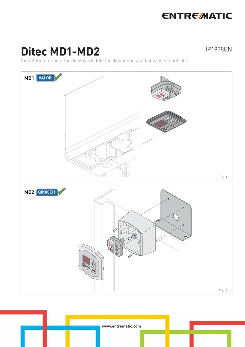
Entrematic Ditec MP1 User manual

MP1 IP1960EN
rev. 2012-01-23
Installation manual for accessories connection module for EL20 control panel.
EN
DITEC S.p.A.
Via Mons. Banfi, 3 - 21042 Caronno Pertusella (VA) - ITALY
Tel. +39 02 963911 - Fax +39 02 9650314
3
4
62 1 5

2
,3,7
MP1
REX
TEN
MP1
MECHANICAL INSTALLATION

3,3,7
MP1
VALOR
VALORHH
VALORHS
MP1

4
,3,7
GENERAL SAFETY WARNINGS
This installation manual is intended for professionally competent personnel only. Installation, electri-
cal connections and adjustments must be performed in accordance with Good Working Methods and
in compliance with the present standards. Read the instructions carefully before installing the product. Bad
installation could be dangerous. Before installing the product, make sure it is in perfect condition. Use original
spare parts only for repairs or replacements of products.
1. ELECTRICAL CONNECTIONS
1.1 Commands
Command Function Connection
013A27
2
7
Connection of opening sensor or button, in-
ner side.
The closure of the contact causes the open-
ing of the door.
Connect the sensor to terminals 0-1-3A, as
described on page 8-9-10-11.
Connect the button to terminals 1-3A.
013A27
Connection of partial opening sensor or but-
ton, inner side.
The closure of the contact causes the door to
open partially.
Connect the sensor to terminals 0-1-27-3A.
Connect the button to terminals 27-3A.
013B27
2
7
Connection of opening sensor or button, out-
er side.
The closure of the contact causes the open-
ing of the door.
Connect the sensor to terminals 0-1-3B, as
described on page 8-9-10-11.
Connect the button to terminals 1-3B.
013B27
Connection of partial opening sensor or but-
ton, outer side.
The closure of the contact causes the door to
open partially.
Connect the sensor to terminals 0-1-27-3B.
Connect the button to terminals 27-3B.
41
Connection of closing command.
The closure of the contact causes the closing
of the door.
1KO KCKC
Connection of opening key.
The closure of the contact causes the open-
ing of the door.
With the functions selector positioned on
NIGHT-TIME CLOSURE, the delayed STOP
procedure is initiated: two-way 10 s, door
closed (max 60 s), STOP.
Connect the key contact to terminals 1-KO,
as described on page 8-9-10-11.
1KO KC
KO
Connection of closing key.
The closure of the contact causes the closing
of the door, even with the functions selector
positioned on NIGHT-TIME CLOSURE.
Connect the key contact to terminals 1-KC,
as described on page 8-9-10-11.
PTS
Voltage-free contact for visual/acoustic sig-
nal indicating the passing of people.
The opening of the closure safety contact
on the control panel closes the PTS contact.
If contact 8 remains permanently open, the
PTS contact will be intermittently activated
[ON=1.5 s, OFF=4 s].
Connect the device to terminals PTS, as de-
scribed on page 8-9-10-11 (max 24 V / 0.5 A).
WARNING: make a jumper for all the N.C. contacts if not in use. The terminals with the same number
are equal.

5,3,7
Command Function Connection
0 116A6B41
Connection of opening safety sensor, left
side.
The opening of the contact decreases the
opening speed in the last 500 mm of the door
wing stroke.
NOTE: advanced command management is
available with the MD1 display module.
Connect the device to terminals 0-1-6A-41,
as described on page 8-9-10-11.
NOTE: make a jumper for terminals 6A-41 if
the sensor is not used.
Connection of opening safety sensor, right
side.
The opening of the contact decreases the
opening speed in the last 500 mm of the door
wing stroke.
NOTE: advanced command management is
available with the MD1 display module.
Connect the device to terminals 0-1-6B-41,
as described on page 8-9-10-11.
NOTE: make a jumper for terminals 6B-41 if
the sensor is not used.
0 118A8B41
Connection of closing safety sensor, inner
side.
The opening of the contact during the closure
manoeuvre causes the movement to invert
(re-opening).
Connect the device to terminals 0-1-8A-41,
as described on page 8-9-10-11.
NOTE: make a jumper for terminals 8A-41 if
the sensor is not used.
Connection of closure safety sensor, outer
side.
The opening of the contact during the closure
manoeuvre causes the movement to invert
(re-opening).
Connect the device to terminals 0-1-8B-41,
as described on page 8-9-10-11.
NOTE: make a jumper for terminals 8B-41 if
the sensor is not used.
192929
Connection of the STOP command.
All movements are stopped when the con-
tact is opened. All normal or emergency op-
erations are excluded when the contact is
opened.
WARNING: when the contact closes again
the door proceeds with the interrupted ma-
noeuvre.
1929
9
Connection of the POWER RESET com-
mand.
All acquired data is annulled when the con-
tact is closed.
The automation can start acquisition again
after 3 seconds.
BST
Voltage-free contact for visual/acoustic sig-
QDOLQGLFDWLQJEDWWHU\HI¿FLHQF\
:LWK',3 21WKHEDWWHU\HI¿FLHQF\WHVWLV
activated; if the test fails, the BST contact will
be closed.
Connect the device to terminals BST, as de-
scribed on page 8-9-10-11 (max 24 V / 0,5 A).
1 G1G2
GENERAL PURPOSE input and output. See instructions on page 7.
1
LM LC
Selection of door illumination.
- The closing of the contact 1-LC activates
the illumination, according to the mode set
for contact 1-LM.
- The closing of contact 1-LM activates per-
manent illumination.
- The opening of contact 1-LM activates the
illumination during the movement of the au-
tomation, with delayed switch-off that can
be adjusted via trimmer A.

6
,3,7
1.2 Adjustments
Description MIN. MAX.
A Automation illumination. Adjusts the switch-off delay of the spotlights that illumi-
nate the door. 0 s 120 s
B FUTURE USE
C FUTURE USE
D FUTURE USE
Description OFF ON
DIP1 Advanced battery test. Disabled. Enabled.
DIP2 FUTURE USE //
DIP3 FUTURE USE //
DIP4 FUTURE USE //
Description OFF ON
J4 Fire mode. Enabled. Disabled.
J5 Operation selection in fire mode. Closing. Opening.
2. ADVANCED BATTERY TEST
With DIP1=ON, the control function for battery charge status is activated.
If one of the following abnormal conditions occurs:
- mains failure;
- missing batteries or a short circuit;
- run-down batteries (the check is performed on every starting and every 4 hours);
the door opens and remains open (the door remains closed if it is set in NIGHT mode, or with contact 1-9
open), and the BST contact of the control panel is closed.
Thealarm signalling(viathevisualand/oracousticdeviceconnectedas describedonpage 8-9-10-11) continues
as long as the abnormal situation persists.
Itispossible to reset the alarm condition (contact 1-29POWER RESET of the control panel),usingakeybutton
or a function selector. If the alarm continues, contact Technical Assistance.
If the batteries are run down, wait about 30 minutes to allow for recharging.
i
NOTE: if connected with ONDA-VOLO automations, consult the respective technical manuals.
Command Function Connection
NO NC C
Voltage-free contact for door lighting or other
interface functions. Use the contact for activation of lights or
other loads in series to the C-NO terminals
as described on page 8-9-10-11 (max 24 V
/ 0.5 A).

7,3,7
3. FIRE MODE
Command Function Connection
1 G1G2
:LWK- 2))WKH¿UHPRGHLVDFWLYDWHG
The opening of contact 1-G2, or the lack of
mains voltage, causes the immediate and
slow start of the operation set via J5 and the
closingofthe contact C-NO (DOORLIGHTS).
All the inputs are deactivated.
&RQQHFW WKH ¿UHVPRNH VHQVRU WR WHUPLQDOV
1-G2.
1KO KCK
C
7KH FORVLQJ RI WKH FRQWDFW GXULQJ WKH ¿UH
alarm phase causes the emergency opening
of the door.
After the set automatic closing time, the door
closes slowly.
1KO KC
KO
7KH FORVXUH RI WKH FRQWDFW GXULQJ WKH ¿UH
alarm phase causes the emergency closure
of the door.
After the set automatic closing time, the door
opens slowly.

8
,3,7
4. EXAMPLE OF APPLICATION WITHOUT SELECTOR
The automation opens with commands 1-3A, 1-3B of the RADARs (or opens partially with the 27-3A, 27-3B
commands), and automatically closes with jumper 1-2. Makes the safety on the passage opening with CELPR
photocells.
If the automation has no blocking device, make connection 1-28 as shown in the figure.
24 V +
-
Internal
radar
External
radar
1
24 V +
-
2
24 V +
-
Left
opening
safety
Right
opening
safety
3
24 V +
-
4
24 V +
-
Door lights
24 V
Stop
Power reset
Key open
Closing
Key close
Battery
status
24 V
Pass signal
24 V
NO NC C
General
purpose
Internal
closing
safety
External
closing
safety
013A27 013B27 41 1 KO KC PTS
0 116A6B41 1 929 BST 1 G1G2
0 118A8B41 1
LM LC
A B C D
ON
OFF 123 4
J4 J5
5
24 V +
-
6J1J2J3
0112 3A 3B 9 27 28 29
ON
OFF 123 4 5 6
SA
POWER
ALARM IN
VA R1VC TC RP
OPEN
016841
R1SR R2
P1 SP P2
012122
CELPR
P1 R1
WARNING: do not use the terminal board of the control panel; make the connections shown in the
figure.

9,3,7
5. EXAMPLE OF APPLICATION WITH COMH-COMK SELECTOR
The automation opens with commands 1-3A, 1-3B of the RADARs (or opens partially with the 27-3A, 27-3B
commands), and automatically closes according to the operation chosen on the selector. Makes the safety on
the passage opening with the CELPR photocells.
24 V +
-
Internal
radar
External
radar
1
24 V +
-
2
24 V +
-
Left
opening
safety
Right
opening
safety
3
24 V +
-
4
24 V +
-
Door lights
24 V
Stop
Power reset
Key open
Closing
Key close
Battery
status
24 V
Pass signal
24 V
NO NC C
General
purpose
Internal
closing
safety
External
closing
safety
013A27 013B27 41 1 KO KC PTS
0 116A6B41 1 929 BST 1 G1G2
0 118A8B41 1
LM LC
A B C D
ON
OFF 123 4
J4 J5
5
24 V +
-
6J1J2J3
0112 3A 3B 9 27 28 29
ON
OFF 123 4 5 6
SA
POWER
ALARM IN
VA R1VC TC RP
OPEN
016841
R1SR R2
P1 SP P2
012122
CELPR
P1 R1
1 2 AB9 27 28 29
COMH
COMK
WARNING: do not use the terminal board of the control panel; make the connections shown in the
figure.

10
,3,7
6. EXAMPLE OF APPLICATION WITH COME SELECTOR
The automation opens with commands 1-3A, 1-3B of the RADARs (or opens partially with the 27-3A, 27-3B
commands), and automatically closes according to the operation chosen on the selector. Makes the safety on
the passage opening with the CELPR photocells.
24 V +
-
Internal
radar
External
radar
1
24 V +
-
2
24 V +
-
Left
opening
safety
Right
opening
safety
3
24 V +
-
4
24 V +
-
Door lights
24 V
Stop
Power reset
Key open
Closing
Key close
Battery
status
24 V
Pass signal
24 V
NO NC C
General
purpose
Internal
closing
safety
External
closing
safety
013A27 013B27 41 1 KO KC PTS
0 116A6B41 1 929 BST 1 G1G2
0 118A8B41 1
LM LC
A B C D
ON
OFF 123 4
J4 J5
5
24 V +
-
6J1J2J3
0112 3A 3B 9 27 28 29
ON
OFF 123 4 5 6
SA
POWER
ALARM IN
VA R1VC TC RP
OPEN
016841
R1SR R2
P1 SP P2
012122
CELPR
P1 R1
MD1 COME
1
4 5 6
3
2
WARNING: do not use the terminal board of the control panel; make the connections shown in the
figure.

11 ,3,7
7. EXAMPLE OF APPLICATION FOR HOSPITAL DOORS
The automation opens with commands 27-3A and 27-3B, and automatically closes with jumper 1-2. Makes
the safety on the passage opening with the CELPR photocells.
Door lights
24 V
Key open
Closing
Key close
Battery
status
24 V
Pass signal
24 V
NO NC C
General
purpose
013A27 013B27 41 1 KO KC PTS
0 116A6B41 1 929 BST 1 G1G2
0 118A8B41 1
LM LC
A B C D
ON
OFF 123 4
J4 J5
J1J2J3
0112 3A 3B 9 27 28 29
ON
OFF 123 4 5 6
SA
POWER
ALARM IN
VA R1VC TC RP
OPEN
016841
R1SR R2
P1 SP P2
012122
CELPR
P1 R1
External push-button
Internal push-button
Stop
Power reset
WARNING: do not use the terminal board of the control panel; make the connections shown in the
figure.

TM
DITEC S.p.A. 9LD0RQV%DQ¿&DURQQR3OOD9$,WDO\7HO)D[
www.ditec.it [email protected]
DITEC BELGIUM LOKEREN Tel. +32 9 3560051 Fax +32 9 3560052 www.ditecbelgium.be DITEC DEUTSCHLAND OBERURSEL
Tel. +49 6171 914150 Fax +49 6171 9141555 www.ditec-germany.de DITEC ESPAÑA ARENYS DE MAR Tel. +34 937958399
Fax +34 937959026 www.ditecespana.com DITEC FRANCE MASSY Tel. +33 1 64532860 Fax +33 1 64532861 www.ditecfrance.com
DITECGOLDPORTA ERMESINDE-PORTUGAL Tel.+351229773520 Fax+351229773528/38 www.goldporta.com DITECSWITZERLAND
BALERNA Tel. +41 848 558855 Fax +41 91 6466127 www.ditecswiss.ch DITEC ENTREMATIC NORDIC LANDSKRONA-SWEDEN
Tel. +46 418 514 50 Fax +46 418 511 63 www.ditecentrematicnordic.com DITEC TURCHIA ISTANBUL Tel. +90 21 28757850
Fax +90 21 28757798 www.ditec.com.tr DITEC AMERICA ORLANDO-FLORIDA-USA Tel. +1 407 8880699 Fax +1 407 8882237
www.ditecamerica.com DITEC CHINA SHANGHAI Tel. +86 21 62363861/2 Fax +86 21 62363863 www.ditec.cn
Table of contents
Other Entrematic Control Unit manuals