5
IP2095 - 2015-05-12
General safety precautions
This installation manual is intended for professionally competent
personnel only. Read the instructions carefully before beginning
to install the product. Incorrect installation may be a source of danger.
Packaging materials (plastic, polystyrene, etc.) must not be allowed to
litter the environment and must be kept out of the reach of children for
whom they may be a source of danger. Before beginning the installation
check that the product is in perfect condition.
For repairs or replacements of product only original spare parts must
be used. These instruction must be kept and forwarded to all possible
future user of the system.
EC declaration of conformity
The manufacturer Entrematic Group AB, with headquarters in Lodjursga-
tan 10, SE-261 44 Landskrona, Sweden, declares that the safety device
GOPAVR, GOPAVRS, GOPAVT, SOFA15, SOFA20, SOFA25, SOFB15, SOFB20,
SOFB25 is compliant to the following european directives and regulations:
EN12978, EN12453, EN12445;
Directive 1999/5/EC R&TTE;
EMC directive 2004/108/EC.
Landskrona, 2015-05-05 Marco Zini
(President & CEO)
1. Technical data
GOPAVR-GOPAVRS power supply 24 V
GOPAVT power supply 3 V type CR123A
lithium battery
GOPAVR-GOPAVRS absorption 60 mA max
GOPAVT absorption <100 μA (average value)
Frequency 868,95 MHz (JR2=ON)
869,85 MHz (JR2=OFF)
Power <10 mW
Range 20 m max
Output contact 24 V / 1A (resistive load)
Termination resistance 8,2 kΩ
Operating temperature -20° C - +55° C
Degree of protection IP55
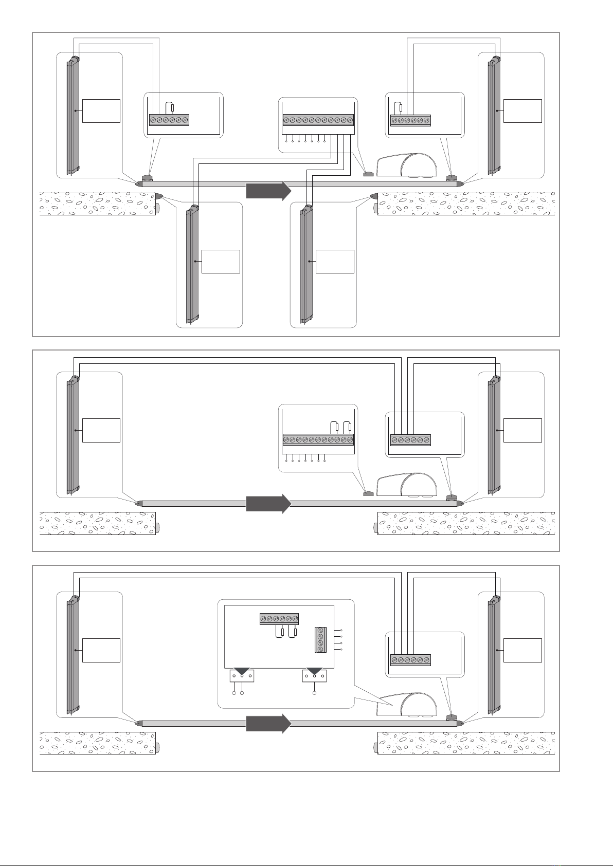
2. Applications
The GOPAV radio system for sensitive edges is intended for use as a
safety device for motorized vertical doors or gates in conjunction with
SOF sensitive edges. The system can be connected to the IN1 and/or IN2
inputs which can be found both on the fixed GOPAVR-GOPAVRS unit as
well as on the mobile GOPAVT unit.
The fixed GOPAVR-GOPAVRS unit can manage up to 5 mobile GOPAVT
units. The fixed unit’s OUT1 and OUT2 outputs are respectively activated
by the IN1 and IN2 inputs, which can be found on both the fixed unit itself,
as well as on each mobile unit associated with it.
The fixed GOPAVR-GOPAVRS unit is also equipped with SAFETY TEST
terminal 41. The mobile GOPAVT units are equipped with batteries and
do not have to be connected to a control panel. Whenever the sensitive
edges connected to each mobile GOPAVT unit are activated, due to the
presence of an obstacle during opening or closing operations, the event
is transmitted by radio to the fixed GOPAVR-GOPAVRS unit.
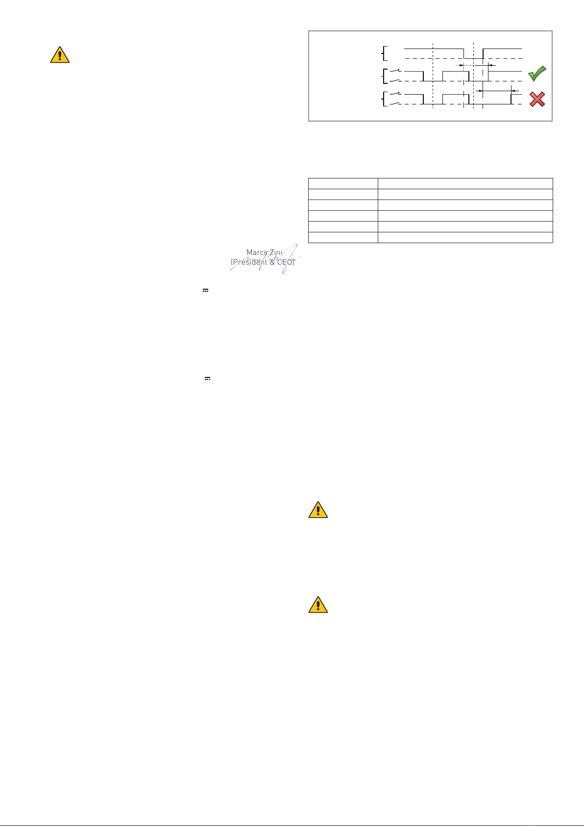
3. Installation conditions
- The product must be used together with sensitive edges of a sufficient
height to guarantee the the respect of the force limits provided for by
the EN12453-EN12445 standards.
- After every activation of the safety device, the gate control panel must
cause a motion reversal for at least 0.5 s.
- In order to comply with EN12453-EN12445 standards the product
must be tested at least once per monouvre cycle applying a negative
polarity impulse to terminal 41 as indicated in the figure.
NOTE: when terminal 41 is not connected to the relative terminal on
the control panel, LED indicators SC and OC on the fixed unit remain
lit.
- The time until the door or gate leaves the same end position again
shall be more than 20 s.
- A normal door or gate movement shall not start if a safety output is
not switched on within 5 s after the test input is switched on again.
- Up to 5 moving units can be installed in one system.
- To comply with legal requirements concerning occupation of the
radio transmission band, according to the number of moving units
in the system, the trigger limits for the installed safety edges must
be complied with as in the values in the table below.
Mobile units Max. number safety edge operations per hour
1 360
2 360
3 360
4 240
5 120
- It is very important to ensure there is good communication between
the various moving units and the corresponding fixed unit.
The values shown in the table refer to optimum communication con-
ditions. If communication is disturbed or inefficient, the maximum
number of operations allowed may be lower than the values shown
in the table.
- In order to ensure sufficient radio capacity, the GOPAV devices must
not be installed within any type of metallic casing.
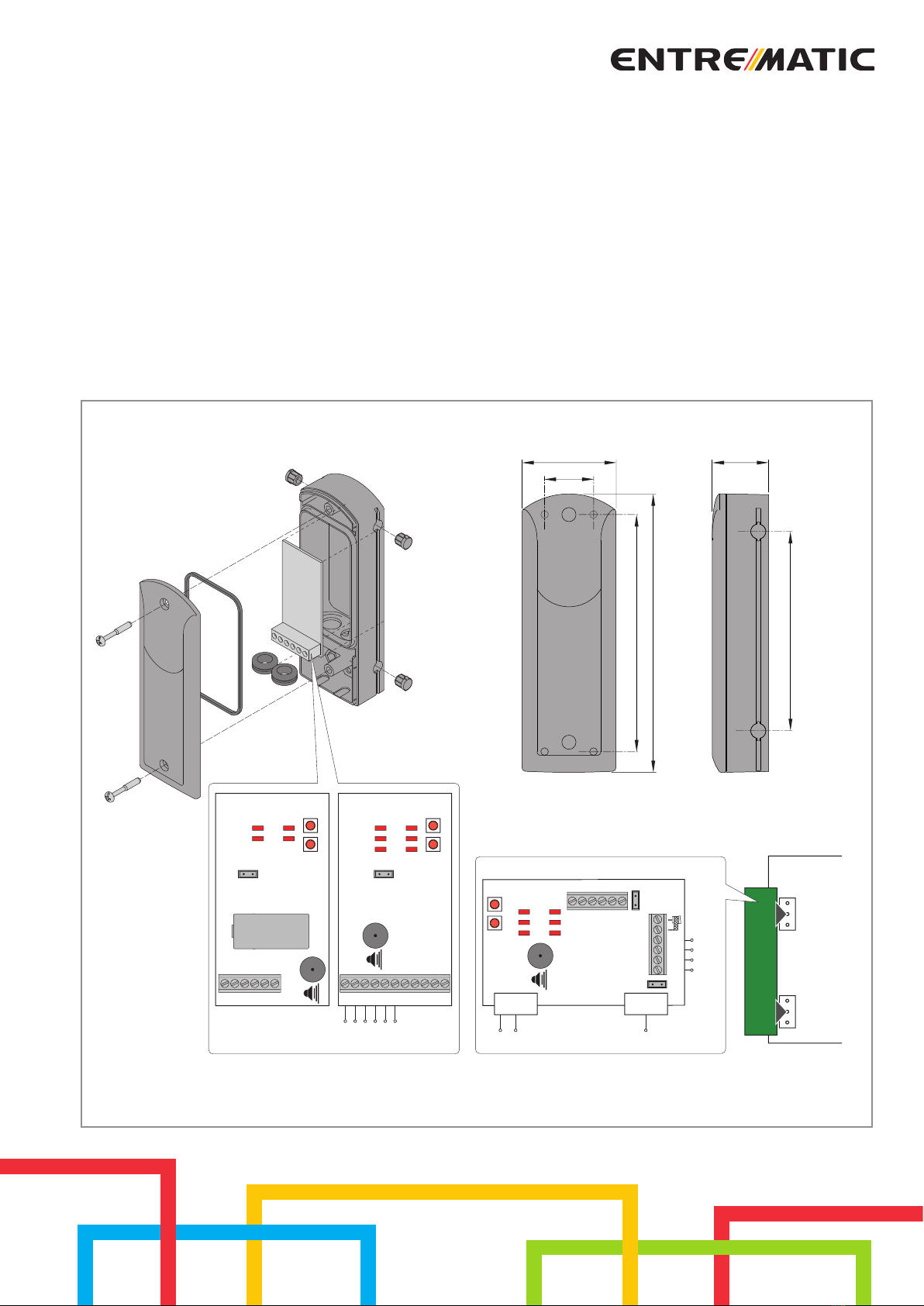
4. Installation
- The fixed GOPAVR unit must be either wall-mounted or otherwise
mounted on upon an appropriate support near the control panel.
- The GOPAVRS fixed unit must be inserted in one of the AUX ports on
the control panel or in the CONT1 card-holder base.
- One or more mobile GOPAVT units must be mounted directly upon
the wing of the gate or door and each must be connected to one or
two SOF sensitive edges, as shown in fig. 2-3-4.
5. Electrical connections
Perform the electrical connections as indicated in fig. 2-3-4.
Remove the terminating resistor from the IN1 or IN2 terminal to be used
and connect the relative SOF sensitive edges to the terminal.
The terminating resistors must not be removed from any inputs which
are not being used.
WARNING: the use of the SAFETY TEST function through terminal
41 is obligatory for compliance with the EN12453-EN12445 stan-
dards. Control panels without terminal 41 can be used by making a
jumper for terminals 1-41 on the GOPAVR-GOPAVRS fixed unit and ope-
ning the JR1 jumper on the GOPAVRS unit only. In this case, however, the
system WILL NOT BE COMPLIANT WITH THE EN12453-EN12445 STAN-
DARDS.
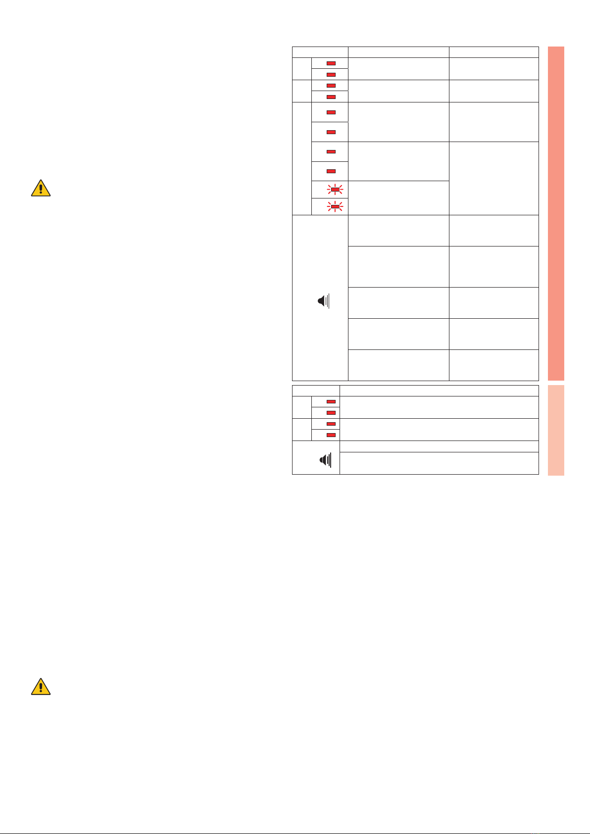
6. Configuration
WARNING: remove the batteries from all of the mobile units be-
fore proceeding with the configuration.
Configure the devices as indicated:
- connect the fixed GOPAVR-GOPAVRS unit to its electrical power supply,
normally W LEDs will flash and output contacts OUT1 and OUT2 will
be open;
- check terminal 41 is correctly connected to the corresponding ter-
minal of the control panel;
- insert the mobile GOPAVT unit’s battery into its appropriate lodging,
all of the LED indicators on the mobile unit will flash;
- press button A on the fixed GOPAVR-GOPAVRS unit, the W LED in-
dicators on the fixed unit with turn on and the OC LED indicators on
the mobile unit will flash;
- press button A on the mobile GOPAVT unit, the LED indicators on the
mobile unit and the fixed unit will turn off;
- check for proper configuration by activating the sensitive edge in ques-oper configuration by activating the sensitive edge in ques-
tion: check that the fixed GOPAVR-GOPAVRS unit’s W LED indicator
turns on and check that the mobile GOPAVT unit’s IN LED indicator
turns on in relation to the output to which the sensitive edge is con-
Test input
terminal 41
Safety output
(OUT1-OUT2)
Safety output
(OUT1-OUT2)
Test
0
24V
max 400 ms
~5 s
Detection
Test fails
ENGLISH