Entrya ET-8000 User manual

NL TECHNISCHE EIGENSCHAPPEN :
Voedingsspanning: 12/24V AC/DC;
Max. bereik: 20mt;
Max stroomverbruik: 40mA;
Verbruik[12V]: ~ 0,5W + 0,5W;
Verbruik [24V]: ~ 1W + 1W;
Bedrijfstemperatuur: -20°C <-> 60°C;
Uitgangsindicator: Rode LED;
INSTALLEREN EN UITLIJNEN :
• Monteer de fotocellen op een stabiele wand, zodat de fotocelzender (TX) en -ontvanger (RX) met elkaar zijn uitgelijnd.
• Haal de kabels door de opening (D) en sluit de draden aan op de aansluitklemmen. (NO-contact voor bedieningstoebehoren / NC- contact
voor veiligheidstoebehoren)
• Sluit de spanning aan en controleer de uitlijning dmv. de rode LED (C): rode LED aan wil zeggen dat de fotocellen niet goed zijn uitgelijnd, of
dat een obstakel de IR-straal belemmert. Als LED (C) uit is, duidt dit op goed uitgelijnde fotocellen.
• Indien het niet mogelijk is de fotocellen goed uit te lijnen, zet dan het kogelgewricht (A) van de optiek los, richt de zender en/of onvanger goed
uit en zet het kogelgewricht (A) terug vast.
• Plaats het deksel terug op de fotocelzender en -ontvanger en sluit goed af.
NL
FR
FR
DONNÉES TECHNIQUES :
Alimentation: 12/24V AC/DC;
Portée: 20mt;
Absorption: 40mA;
Puissance [12V]: ~ 0,5W + 0,5W;
Puissance [24V]: ~ 1W + 1W;
Température de travail: -20°C <-> 60°C;
Signal de fonctionnement: Led Rouge;
MONTAGE ET ALIGNEMENT :
• Fixer les bases des photocellules aux parois de façon à ce que l’émetteur [TX] et le récepteur [RX] soient alignés.
• Introduire les câbles électriques de raccordement à travers le trou prévu à cet effet [D] et effectuer les branchements à la centrale de comman-
de.
• Pour contrôler l’alignement, alimenter les deux photocellules et vérier l’état de la led rouge [C] sur le récepteur : si elle est allumée, elle
indique que les photocellules ne sont pas alignées ou qu’il y a un obstacle sur le parcours optique. Si elle est éteinte, elle indique l’alignement
correct des photocellules.
• Si il n’est pas possible d’aligner le deux parties de manière précise, desserrer les pattes de xation [A] des bulbes [B], régler l’optique de l’ém-
etteur et/ou du récepteur jusqu’à l’alignement et resserrer les pattes de xation [A] .
• Remettre les couvercles sur les dispositifs.
N.C.: contact sec pour les photocellules soit les accessoires de securité;
N.O.: contact ouvert pour les accessoires de commande;
Man.ET8000 Rev.05/2015
DE
DE
TECHNISCHE DATEN:
MONTAGE UND AUSRICHTUNG :
Betriebsspannung: 12/24V AC/DC;
Reichweite: 20mt;
Stromaufnahme: 40mA;
Leistung(12V): 0,5W + 0,5W;
Leistung(24V): 1W + 1W;
• Montieren Sie die Lichtschranken so , dass Sender [TX] und Empfänger [RX] gegeneinander ausgerichtet sind.
• Führen Sie das Kabel durch die Öffnung [D] und stellen Sie die Verbindung zur Steuerung her .
• Sender [TX] und Empfänger [RX] mit Spannung versorgen ; die korrekte Ausrichtung mittels der roten LED [C] am Empfänger [RX] überprüfen.
• LED leuchtet : Lichtschranke ist nicht ausgerichtet oder der Lichtstrahl ist durch ein Hindernis unterbrochen .
• LED leuchtet nicht: Lichtschranke ist ausgerichtet .
• Wenn Sender und Empfänger nicht präzise ausgerichtet sind , lockern Sie die Befestigung (A) der Kugelgelenksoptiken , justieren Sie Sender
und/oder Empfänger und schrauben die Kugelgelenksbefestigung [A] wieder fest.
• Sender und Empfänger mit den zugehörigen Deckeln schliessen.
Betriebstemperatur: 20° <-> 60°C;
Funktionsanzeige: LED rot;
IT
Alimentazione: 12/24V AC/DC;
Portata: 20mt;
Assorbimento: 40mA;
Potenza[12V]: ~ 0,5W + 0,5W;
Potenza [24V]: ~ 1W + 1W;
DATI TECNICI:
IT
• Fissare le basi delle fotocellule alle pareti in modo che la parte trasmittente[TX] e quella ricevente[RX] risultino allineate.
• Introdurre i cavi elettrici di collegamento attraverso il foro predisposto[D] ed effettuare le connessioni alla centrale di comando.
• Per controllare l’allineamento occorre alimentare le due fotocellule e vericare lo stato del led rosso[C] sul ricevitore: se acceso, indica che le
fotocellule non sono allineate o la presenza di un ostacolo lungo il loro percorso ottico. Se spento, indica il corretto allineamento delle fotocel-
lule.
• Nel caso in cui non sia possibile allineare le due parti in maniera precisa, allentare le staffe di ssaggio[A] dei bulbi[B], regolare l’ottica del
trasmettitore e/o del ricevitore no al raggiungimento dell’allineamento e bloccare nuovamente le stesse staffe[A].
• Chiudere i dispositivi con i rispettivi coperchi.
MONTAGGIO E ALLINEAMENTO:
Temperatura di lavoro: -20°C <-> 60°C;
Output di segnalazione: Led Rosso;

ET-8000
DIMENSIONS / AFMETINGEN
DIMENSIONS / GRÖSSE / DIMENSIONI
110mm
30mm
40mm
CENTERING / UITLIJNEN
CENTRAGE / ZENTRIERUNG / CENTRATURA
10°
10°
180°
[A]
[B]
[C]
[D]
[A]
[B]
[C]
[D]
12/24 V
AC/DC
+ -
~ ~
12/24 V
AC/DC
+ -
~ ~
COM
RX TX
DESCRIPTION / OMSCHRIJVING / DARSTELLUNG / DESCRIZIONE WIRING / AANSLUITINGEN / CÂBLAGE/ ANSCHLUSS / CABLAGGIO
CLOSING / TERUGPLAATSEN
FERMATURE / SCHLIESSUNG / CHIUSURA
N.C.
ENTRYA TECHNOLOGIES declare on our own responsibility that operating device of ET-8000 comply with the following standards and directives:
2004/108 EC
2006/95 EC
24V
ac/dc
PHOT
COM
CENTRALE DI COMANDO / CONTROL BOARD /
CENTRAL COMMAND /
CONTROL BOARD / BESTURING / PLATINE DE COMMANDE / STEUERPLATINE / QUADRO DI COMMANDO
EN TECHNICAL DATA:
Power supply: 12/24V AC/DC;
Intervention distance: 20mt;
Max input: 40mA;
Power[12V]: ~ 0,5W + 0,5W;
Power [24V]: ~ 1W + 1W;
Working temperature: -20°C <-> 60°C;
Output signal: Red LED;
MOUNTING AND ALIGNING :
• Install the photocell on the wall in order the [TX] transmitter is aligning with the [RX] receiver.
• Pass the electric cables through the hole [D] and connect them to the terminal.
• To check the alignment, power the two photocells and check the status of the [C] red led on the receiver : if on, it means that photocells are
misaligned or there is an obstacle along the optical path. If off, it means that photocells are correctly aligned.
• If it is impossible to align the photocell accurately, loosen the relative collar [A] of the bulbs, adjust the transmitter and/or receiver optics until
they are rightly aligned and then tighten the [A] collar again.
• Close the devices with their caps.
EN
Table of contents
Popular Controllers manuals by other brands

Milltronics
Milltronics EnviroRanger ERS500 installation guide
Lumel
Lumel SPC5 Service manual
Regin
Regin RVAZ4L1-230 Instruction
Renkforce
Renkforce 1688015 operating instructions
Duff-Norton
Duff-Norton SK-2389-T Installation, operation & maintenance instructions

National Instruments
National Instruments SCXI USB-1357 installation guide
Sporlan
Sporlan Superheat Installation and operation instructions
sunsei
sunsei CC25000 operating instructions
Motorola
Motorola MVME162P4 Series Installation and use manual

ARM
ARM Cortex-A9 MBIST Technical reference manual
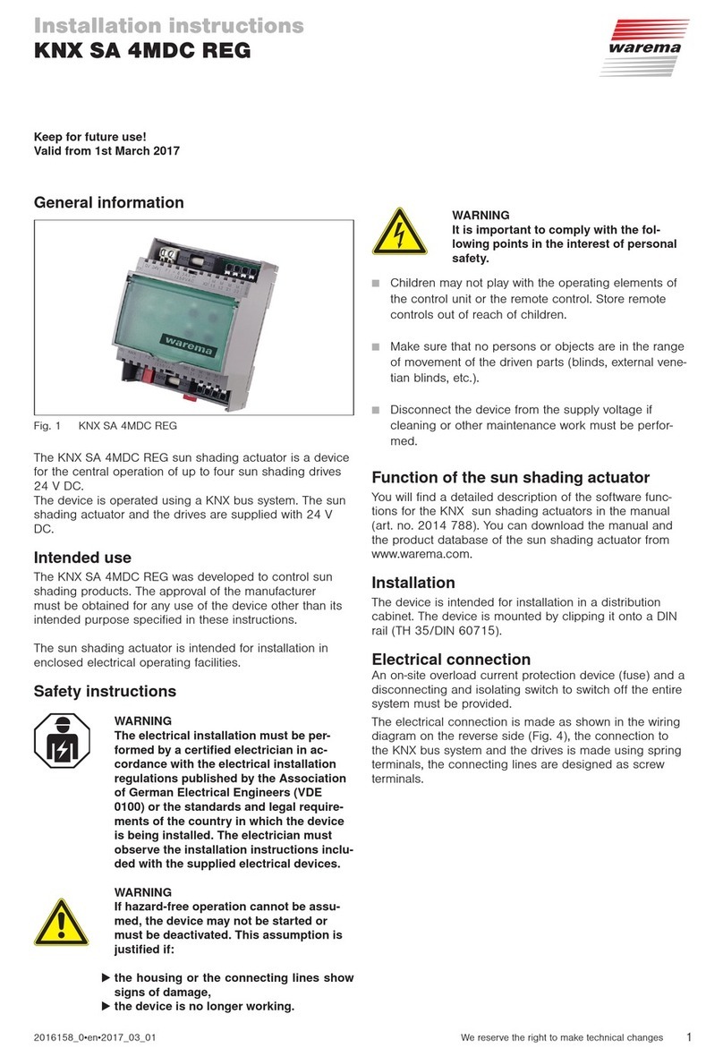
WAREMA
WAREMA KNX SA 4MDC REG installation instructions

DELTA DORE
DELTA DORE TYXIA 631 manual
