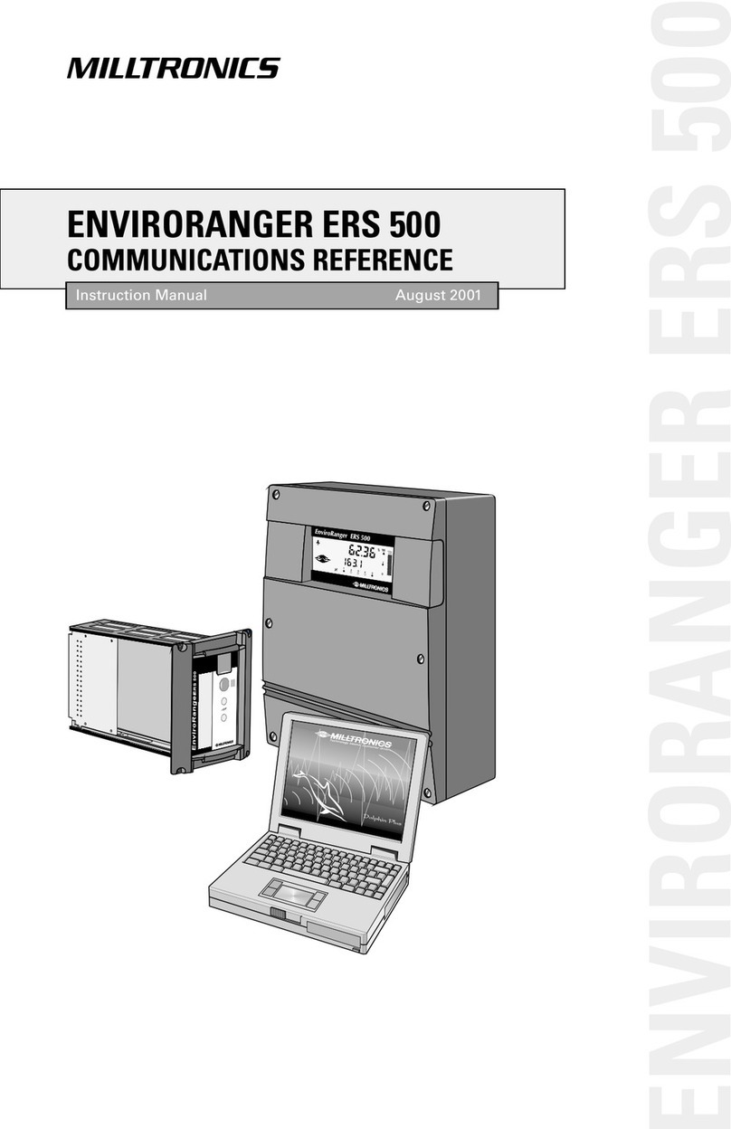
Milltronics EnviroRanger ERS500 User manual

Nov 1999
ISO 9001
Certificate #002284
Peterborough, Ont., Canada
R
E
G
I
S
T
E
R
E
D
Q
U
A
L
I
T
Y
S
Y
S
T
E
M
R
CANADA
GERMANY
Singapore, Brazil
1954 Technology Dr., P.O. Box 4225,
Peterborough, Ontario, Canada K9J 7B1
Tel.: (705) 745-2431 Fax: (705) 741-0466
August van de Wielelei 97, 2100 Deurne, Antwerp, Belgium
Tel.: +32(0)3326 45 54 Fax: +32(0)3326 05 25
Parc de la Sainte Victoire, Bât. 5, 13590, Meyreuil, France
Tel.: +33 4 42 65 69 00 Fax: +33 4 42 58 63 95
Amores No. 1155, Col. Del Valle, 03100, Mexico D.F.,
Mexico
Tel.: +52 5 575-27-28 Fax: +52 5 575-26-86
Nikkelstraat 10, NL-4823 AB Breda, The Netherlands
Tel.: +31(0)76 542 7 542 Fax: +31(0)76 542 8 542
709 Stadium Drive, Arlington, Texas U.S.A. 76011
Tel.: (817) 277-3543 Fax: (817) 277-3894
A joint venture in a sales office in and
distributors in 56 countries.
AUSTRALIA
BELGIUM
ENGLAND
FRANCE
HONG KONG
MEXICO
THE NETHERLANDS
THE UNITED STATES
182 Normanby Rd., Box 339, South Melbourne, Australia
Tel.: +011-613-9695-2400 Fax: +011-613-9695-2450
Century House, Bridgwater Road, Worcester, England WR4 9ZQ
Tel: +44 1905 450500 Fax: +44 1905 450501
Werftstrasse 47, D-40549, Dusseldorf, Germany
Tel: +00 49 211 562 3925 Fax: +00 49 211 562 6030
1 Hoi Wan Street, Suite 602, Quarry Bay, Hong Kong
Tel.: +011 852-2856-3166 Fax: +011 852-2856-2962
Visit our web site at:
www.milltronics.com
Installation Guide
PL-557
33455570
Rev 2.0
EnviroRanger ERS 500

Capacitance
Radar
Belt scales
Motion sensing
Weigh feeders
Acoustic sensing
Flowmeters
Ultrasonic level
Point level
Communications
At Milltronics, we endeavour
to design equipment that is
simple to use and reliable in its
operation, with the aim of
satisfying our customers' needs.
Milltronics has been designing
and manufacturing electronics
based process measurement
equipment since 1954. Our
fields of expertise include
continuous and point level
measurement, weighing and
feeding systems and motion
sensing. Technologies include
ultrasonic, capacitance and
microwave radar.
Milltronics sells and markets
world wide through
subsidiaries, distributors and
representatives. Through
continuous improvement, we
are striving to provide our
customers with first rate sales
information, engineering
assistance and after sales
support.
For more details on our
products and services, please
contact us and we will provide
you with a listing of the offices
or representatives nearest you.

PL-557 EnviroRanger Installation Guide Page 3
Table of Contents
Specifications ........................................................................................5
Introduction............................................................................................9
About this Manual ..............................................................9
Dolphin Plus.....................................................................10
Power Interruption ...........................................................10
Symbols Used..................................................................10
Installation............................................................................................11
Environmental..................................................................11
Mounting ..........................................................................12
Installing the Battery ........................................................17
Mounting Location Considerations ..................................18
Installing SmartLinx Cards...............................................19
Wiring ...................................................................................................21
System Diagram ..............................................................21
Terminal Board ................................................................22
Cables..............................................................................23
Transducers..................................................................... 23
Temperature Sensor........................................................24
Relays..............................................................................25
mA Input ..........................................................................26
Level System Synchronization......................................... 26
Power...............................................................................28
Digital Communications ...................................................29
Discrete Inputs.................................................................31
Maintenance......................................................................................... 35
Battery Replacement .......................................................35
Software Upgrades ..........................................................36
Index .....................................................................................................37

Page 4 EnviroRanger Installation Guide PL-557

PL-557 EnviroRanger Installation Guide Page 5
Specifications
Power
{AC version: {100-230 Vac ± 15%, 50 / 60 Hz, 36 VA (17W)1
{fuse: F3: 2 AG, Slow Blow, 0.375A, 250V
{DC version: {12-30 Vdc, 20W1
{fuse: F3: 2 AG, Slow Blow, 3A, 250V
{Transmitter fuse: {F1: Belling Lee, L754, 4000A HRC, ceramic type,
100mA, 250V
{Temp. Sensor fuse: {F2: Belling Lee, L754, 4000A HRC, ceramic type,
50mA, 250V
Environmental, Rack or Panel Mount
{location: {indoor
{altitude: {2000 m max.
{ambient temperature: {-20 to 50°C (-5 to 122°F)
{relative humidity: {80% for temperatures up to 50°C (122°F)
{installation category: {II
{pollution degree: {2
Environmental, Wall Mount
{location: {indoor / outdoor
{altitude: {2000 m max.
{ambient temperature: {-20 to 50°C (-5 to 122°F)
{relative humidity: {suitable for outdoor
{installation category: {II
{pollution degree: {4
Range
{0.3 m (1 ft) to 15 m (50 ft) dependent on transducer
Accuracy
{0.25% of maximum range or 6 mm (0.24”) whichever is greater
Resolution
{0.1% of program range2or 2 mm (0.08”), whichever is greater
1Power consumption is listed at maximum. If no load is placed on the EnviroRanger’s 24V
rails (used to power discrete interlocks on passive devices) then the power consumption
is considerably lower.
2Program range is defined as the empty distance from the face of the transducer (P006)
plus any range extension (P801).

Page 6 EnviroRanger Installation Guide PL-557
Memory
{256KB static RAM with battery backup
{1MB flash EPROM
Programming
{primary: {PC running Dolphin Plus software
{secondary: {hand held programmer
Display
{back lit LCD
Temperature Compensation
{range: {-50 to 150°C (-58 to 302°F)
{source: {integral transducer sensor
{TS-3 temperature sensor
{programmable fixed temperature
Temperature Error
{sensor: {0.09% of range
{fixed: {0.17% per °C deviation from programmed value
Outputs
{transducer drive: {315 V peak
{relays3:{4 control / 1 alarm relay
{control: 4 form “A”, NO relays (number 1-4)
{alarm, rack or panel mount:
1 form “B”, NC relay (number 5)
{alarm, wall mount:
1 form “C”, NO or NC relay (number 5)
{all relays rated 4 A at 250 V ac, non-inductive
{communication: {RS-232 running Milltronics Dolphin protocol
{RS-232 running Modbus RTU and ASCII
{SmartLinx®compatible
Inputs
{mA (analog) (1): {0-20 or 4-20 mA, from alternate device, scaleable
{discrete (8): {10-50 V dc switching level
{logical 0 = < 0.5 V dc
{logical 1 = 10 to 50 V dc
{3 mA max. draw
{frequency (2)4:{1-20,000 Hz
3All relays are certified only for use with equipment which fails in a state at or under the
rated maximums of the relays.

PL-557 EnviroRanger Installation Guide Page 7
{counter (2)4:{5 msec minimum pulse width
Enclosure
{rack mount: {DIN 3U/21HP, 4 rail plug in unit
{suitable for standard 3U/84HP (19”) sub rack
{panel mount: {suitable for DIN 43700 72 x 144 standard panel
cut-out on 110mm (4.33“) centres
{wall mount: {224mm W x 285mm H x 102mm D
(8.8”W x 11.2”H x 4.0”D)
{Type 4X / NEMA 4X / IP 65
{Polycarbonate
Weight
{rack mount: {1.5 kg (3.3lbs)
{panel mount: {1.5 kg (3.3lbs)
{wall mount: {2.5 kg (5.5lbs)
Approvals
{See product nameplate
Compatible Transducers
{Echomax series, ST Ultrason series, STH series
4Discrete inputs 7 and 8 can be configured as frequency inputs, pulse counters, or simple
discrete inputs.

Page 8 EnviroRanger Installation Guide PL-557

PL-557 EnviroRanger Installation Guide Page 9
Introduction
The EnviroRanger is intended for advanced water and wastewater
applications. This device can handle virtually all of your pump control and
level monitoring needs –often replacing expensive PLCs and integrating into
a SCADA system for a fraction of the cost of competitive systems.
The EnviroRanger is programmable.
It can be configured for nearly any water or wastewater application and
control up to five pumps, gates, or alarms –and can communicate its status
by way of direct serial connection, modem, or industrial communication
network.
The EnviroRanger is flexible.
It can take discrete input from pumps or other devices and modify its
operation based on that input. It can also time events to maximize efficiency
or minimize cost.
About this Manual
Note
The EnviroRanger ERS 500 is to be used only in the manner outlined in
this instruction manual or protection provided by the equipment may be
impaired.
This is the Installation Guide for the Milltronics EnviroRanger pump
controller.
The manuals in the EnviroRanger library are:
Manual Uses
Programming Reference
(PL-556)
•Parameter values
•Parameter uses
•Programming methods
Installation Guide
(PL-557)
•Outline diagrams
•Wiring diagrams
•Installation requirements
Communications Reference
(PL-558)
•MODBUS register mapping
•Modem configuration

Page 10 EnviroRanger Installation Guide PL-557
Dolphin Plus
The primary method of programming the EnviroRanger is using the Dolphin
Plus software and a serial connection to the device.
Programming the EnviroRanger using the optional hand programmer is
possible but is not recommended for complex installations. As a rule of
thumb, if your application falls into one of the pre-configured applications
then you can use the programmer but if your application is more complex
then you will want to use Dolphin Plus.
To buy a copy of Dolphin Plus contact your local Milltronics representative at
the numbers given on the back cover.
Power Interruption
All operator programming is stored in non-volatile memory, unaffected by
power interruption. Reporting functions use volatile RAM with battery
backup.
Symbols Used
The following symbols are used in the EnviroRanger manuals:
Symbol Meaning
alternating current
direct current
earth (ground) terminal
protective conductor terminal
caution (refer to instructions)
program button on front of instrument
infra-red communication port on front of instrument
RJ-11 communications port
no co-axial cable connections

PL-557 EnviroRanger Installation Guide Page 11
Installation
Note:
Installation shall only be performed by qualified personnel, and in
accordance with local governing regulations.
Environmental
Choose a mounting location suited to the EnviroRanger enclosure.
The ideal EnviroRanger mounting location is where the:
•Ambient temperature is always within -20 to 50°C (-5 to 122°F)
•EnviroRanger display window is at eye level, unless most interaction is
through a SCADA system
•Cable length requirements are minimal
•Mounting surface is free from vibration
Avoid mounting locations where the EnviroRanger is:
•Exposed to direct sunlight, (otherwise, provide a sun shield).
•Close to high voltage/current runs, contacts, SCR control drives, or
frequency inverters.
This product is susceptible to electrostatic shock. Follow proper grounding
procedures
All field wiring must have insulation suitable for at least 250 V.
Hazardous voltage present on transducer terminals during
operation.
DC terminals shall be supplied from an SELV source in
accordance with IEC 1010-1 Annex H.
Relay contact terminals are for use with equipment having no
accessible live parts and wiring having insulation suitable for
at least 250 V. The maximum allowable working voltage
between adjacent relay contacts shall be 250 V.
The non metallic enclosure does not provide grounding
between conduit connections. Use grounding type bushings
and jumpers.

Page 12 EnviroRanger Installation Guide PL-557
Mounting
Notes:
•Rack and rails supplied by others.
•Terminal board screws supplied by others.
Rack Mount
Installation
1. Install rails at positions 5 and 15, offset from the left of the faceplate.
2. Test the fit of the EnviroRanger to ensure the rails are aligned correctly.
3. Mount the terminal board
on the inside rails of the rack with mounting
screws at positions 6, 10, and 16, offset from the left of the faceplate.
21 HP
3U
18mm
0.71”176mm
6.91”
front view

PL-557 EnviroRanger Installation Guide Page 13
4. Slide the EnviroRanger into the rack and press fit with the rail mounted
terminal board.
5. Tighten the four mounting screws on the faceplate.
6. Wire the unit from the back.
Note:
Metallic racks must be grounded.
3U/84HP (19”) sub-rack
EnviroRanger rack
mount (DIN 3U/21HP)
blanking panels must
cover any unused slots
unit connector
terminal board
(Milltronics supplied)
Terminal board mounted on the
inside of the rear rack rails.

Page 14 EnviroRanger Installation Guide PL-557
Panel Mount
Installation
1. Unlatch the retaining clips and remove the terminal board from the unit.
2. Slide the EnviroRanger through the panel cut-out.
3. Assemble mounting brackets to the EnviroRanger chassis by hooking them
into the top and bottom (bottom first).
72mm
2.8”
144mm
5.7”
152mm
6.0”
11mm
0.4”
195mm
7.7”
slip on mounting bracket
hand tighten (1 in. lb. torque max)
slip on mounting bracket
hand tighten (1 in. lb. torque max)
panel cut out:
68 +0.7 by 138 +1.0 mm
(2.68 +0.03 by 5.43 +0.04 in.)
on 110mm (4.33”) centres
DIN 43700
72 x 144
104mm
4.1”
terminal board extends
beyond panel faceplate

PL-557 EnviroRanger Installation Guide Page 15
4. Tighten mounting bracket clamping screw (top & bottom).
5. Wire the terminal board.
6. Press fit the terminal board to the EnviroRanger. To ensure that the pressure
on the rear of the unit is minimized, provide external support for the wires.
clamping screw
terminal board
(Milltronics supplied)
Ensure wiring is
externally supported
panel material
68+0.7mm
(2.68+0.03”)
41mm minimum
(1.6”)
138+1.0mm
(5.43+0.04”)
clip for terminal board

Page 16 EnviroRanger Installation Guide PL-557
Wall Mount
Installation
1. Mark and drill holes for the four mounting screws (customer supplied)
2. Mount the enclosure using a long screwdriver
The next steps are determined by your cabling system.
Conduit
If your cable is routed through conduit follow these steps:
1. Unplug the display ribbon cable from the motherboard.
2. Remove the four mounting screws holding the motherboard to the enclosure.
3. Remove the motherboard from the enclosure, be careful not to damage the
electronics with static electricity.
4. Drill any required cable entry holes.
5. Attach the conduit to the enclosure.
6. Reinstall the motherboard with the mounting screws and plug in the display
ribbon cable.
209mm
(8.2”)
172mm
(6.8”)
15mm
(0.6”)
267mm
(10.5”)
285mm
(11.2”)
102mm
(4.0”)
mounting holes
(4 places)
28mm
(1.1”)

PL-557 EnviroRanger Installation Guide Page 17
Cable Glands
If your cable is exposed and enters the EnviroRanger enclosure through the
supplied cable glands, follow these steps:
1. Unscrew the glands and attach them loosely to the enclosure.
2. Thread the cables through the glands, ensure the power cable is kept
separated from the signal cables.
3. Wire the cables to the terminal blocks.
4. Tighten the glands to form a good seal.
5. If you require more holes than are supplied in the enclosure, follow the steps
found on page 16.
Installing the Battery
Disconnect power before
installing or replacing the
battery.
Do not install the memory backup battery until the EnviroRanger is installed,
as it begins operation immediately.
The unit is supplied with one battery. Insert the battery into the holder as
shown before using the EnviroRanger.
To install the battery
Rack or Panel Mount
1. Remove the plastic side shield.
2. Slide the battery into the holder being careful to align the + and –terminals
(sides) correctly.
3. Replace the plastic side shield.
Wall Mount
1. Open enclosure lid
2. Slide the battery into the holder being careful to align the + and –terminals
(sides) correctly.
3. Close and tighten enclosure lid

Page 18 EnviroRanger Installation Guide PL-557
Mounting Location Considerations
Laptop Access
When mounting the EnviroRanger try to provide a place for a laptop
computer. A laptop running Dolphin Plus is an excellent configuration and
diagnosis tool for the EnviroRanger.
The Rack and Panel mount versions of the EnviroRanger have a serial (RS-
232) connection on the face of the unit. The
Wall mount version has the serial connection
on the top of the motherboard, inside the
enclosure. See Wall Mount on page 19 for
RJ-11 placement.
All units have RS-232 connections on the
terminal board so they can be permanently
wired to modems for remote access or
telephone jacks for easy local access. Refer
to Digital Communications on page 29 for
information on how to wire a permanent
communications connection to the EnviroRanger terminal board.
Hand Programmer Access
If a laptop is not used to configure the EnviroRanger then ensure there is
enough room in front of the unit to stand with a hand programmer. The hand
held programmer is aimed at the receiver as shown below.
If values from the hand programmer are not accepted (display does not
respond) try repositioning it. For the rack and panel mounted versions,
ensure that the program button is pressed and the unit is in program mode.
RJ-11
Port

PL-557 EnviroRanger Installation Guide Page 19
Installing SmartLinx Cards
Option cards are installed into the areas shown.
Wall Mount
SmartLinx module
power supply
p/n 24751503 = ac
p/n 24751502 = dc
mounting hole
mounting hole RJ-11

Page 20 EnviroRanger Installation Guide PL-557
Rack or Panel Mount
To install the optional SmartLinx card:
1. Press fit the card onto the female connectors as shown in the diagram.
2. Use the screws supplied with the SmartLinx card to mount the card to the
posts on the EnviroRanger.
3. Install and configure the SmartLinx communication card as per the
instructions supplied with the card.
Communication Wiring
The SmartLinx Profibus DP manual (PL-534) shows cabling to a terminal
block. When using a SmartLinx card with the EnviroRanger all wiring should
be made to the EnviroRanger terminal board.
The Profibus terminal block (from PL-534) maps to the EnviroRanger
terminal board as shown:
Profibus DP Wire Rack or Panel Mount Wall Mount
2 Bus Ground 65 1
-- RTS 66 2
3 or 6 A-Line 68 4
4 or 7 B-Line 69 5
1 Vcc 71 7
5 or 8 Cable Shield 22 38
battery
SmartLinx card
mounting screws
wire the
communications
cable to the
SmartLinx terminal
block (65 –73)
Other manuals for EnviroRanger ERS500
4
Table of contents
Other Milltronics Controllers manuals
Popular Controllers manuals by other brands

Datakom
Datakom D-500 user manual

KBR
KBR Multicomp 2F144-NC-1V1C06RO Operating instructions, technical parameters

Comelec
Comelec ECRO RV Technical manual

Johnson Controls
Johnson Controls VA-9070 Series manual

Linear Technology
Linear Technology DC1669A Demo Manual

Altronix
Altronix PT724A Series installation guide