manuals.online logo
Brands
  1. Home
  2. •
  3. Brands
  4. •
  5. Daikin
  6. •
  7. Controllers
  8. •
  9. Daikin System Manager Operating and maintenance instructions

Daikin System Manager Operating and maintenance instructions

Other Daikin Controllers manuals

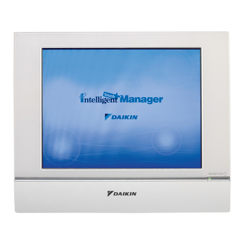
Daikin BRC1H61W User manual

Daikin

Daikin BRC1H61W User manual

Daikin MicroTech III DPS Manual

Daikin

Daikin MicroTech III DPS Manual

Daikin MicroTech III User manual

Daikin

Daikin MicroTech III User manual

Daikin DCS004A51 User manual

Daikin

Daikin DCS004A51 User manual

Daikin BACnet Manual

Daikin

Daikin BACnet Manual

Daikin homecontrols EKRUFHT61V3 User manual

Daikin

Daikin homecontrols EKRUFHT61V3 User manual

Daikin DCC601A51 User manual

Daikin

Daikin DCC601A51 User manual

Daikin RoCon U1 User manual

Daikin

Daikin RoCon U1 User manual

Daikin MicroTech II Manual

Daikin

Daikin MicroTech II Manual

Daikin RoCon HP User manual

Daikin

Daikin RoCon HP User manual

Daikin DPS Manual

Daikin

Daikin DPS Manual

Daikin BRC1H61W User manual

Daikin

Daikin BRC1H61W User manual

Daikin AIRHUB User manual

Daikin

Daikin AIRHUB User manual

Daikin BRC1H61W User manual

Daikin

Daikin BRC1H61W User manual

Daikin RoCon+ HP Series User manual

Daikin

Daikin RoCon+ HP Series User manual

Daikin BRC7E530W User manual

Daikin

Daikin BRC7E530W User manual

Daikin FTXB50C User manual

Daikin

Daikin FTXB50C User manual

Daikin BRC1H62W User manual

Daikin

Daikin BRC1H62W User manual

Daikin BRC1H61W System manual

Daikin

Daikin BRC1H61W System manual

Daikin MD5 User manual

Daikin

Daikin MD5 User manual

Daikin QUG-Altherma Interface Instruction manual

Daikin

Daikin QUG-Altherma Interface Instruction manual

Daikin MicroTech III Manual

Daikin

Daikin MicroTech III Manual

Daikin ALTHERMA User manual

Daikin

Daikin ALTHERMA User manual

Daikin DKN-MP130-24MP User manual

Daikin

Daikin DKN-MP130-24MP User manual

Popular Controllers manuals by other brands

Sunricher SR-ZV9003T3-RGBW-US Installation

Sunricher

Sunricher SR-ZV9003T3-RGBW-US Installation

Ksenia intro Installation and configuration manual

Ksenia

Ksenia intro Installation and configuration manual

Inovance CAN200 Series manual

Inovance

Inovance CAN200 Series manual

Gauzy LC6 FLEX Controller Installation and operation guide

Gauzy

Gauzy LC6 FLEX Controller Installation and operation guide

Viking SLP-1 Technical practice

Viking

Viking SLP-1 Technical practice

CKD KBX-30E-U Series instruction manual

CKD

CKD KBX-30E-U Series instruction manual

Sharp Energy Sun Flux User manual & installation guide

Sharp Energy

Sharp Energy Sun Flux User manual & installation guide

Yamaha RCX40 user manual

Yamaha

Yamaha RCX40 user manual

AB Quality PowerFlex 400 Frames D-H Service bulletin

AB Quality

AB Quality PowerFlex 400 Frames D-H Service bulletin

Yamaha MJC8 owner's manual

Yamaha

Yamaha MJC8 owner's manual

AL-KO ATC operating instructions

AL-KO

AL-KO ATC operating instructions

Savant SmartControl 2 Deployment guide

Savant

Savant SmartControl 2 Deployment guide

GameSir T3S user manual

GameSir

GameSir T3S user manual

Kostal inveor operating manual

Kostal

Kostal inveor operating manual

Emerson Yarway 20-55 Operating and safety instructions

Emerson

Emerson Yarway 20-55 Operating and safety instructions

CoCo ACM-LV24 Quick installation guide

CoCo

CoCo ACM-LV24 Quick installation guide

Brooks SLA5810/20 Installation and operation manual

Brooks

Brooks SLA5810/20 Installation and operation manual

SIGMA TEK SR 011 Technical manual

SIGMA TEK

SIGMA TEK SR 011 Technical manual

manuals.online logo
manuals.online logoBrands
  • About & Mission
  • Contact us
  • Privacy Policy
  • Terms and Conditions

Copyright 2025 Manuals.Online. All Rights Reserved.

Installation Manual IM 1255-1
Group: Controls
Part Number: IM 1255
Date: February 2017
Daikin System Manager
Quick Start Guide
Use with Daikin Intelligent Systems™
Installer Responsibilities
The installation of this equipment shall be in accordance
with the regulations of authorities having jurisdiction and all
applicable codes. It is the responsibility of the installer to
determine and follow the applicable codes.
Receiving Inspection
When the device is received, all items should be carefully
checked against the bill of lading to be sure all packages
have been received.
Inspect the system manager for any shipping damage.
Report all shipping damage to the carrier and le a claim.
Included Items
A. System Manager
B. 15.6" touch screen monitor
C. System Manager display bracket
D. 4 × screws and 4 × 10mm standoffs for VESA
mounting
E. Cables – VGA male to male plug, USB type A to type B
F. 120AC-12VDC adapter with screw lug power
connector
**Wall-mounting screws and anchors are not included
Required Tools
• Screwdriver
• Controls screwdriver
Figure 1: Included Items
A. B. C. D. E. F.
©2017 Daikin Applied | (800) 432–1342 | www.DaikinApplied.com
IM 1255-1 • INTELLIGENT SYSTEM MANAGER 2 www.DaikinApplied.com
Installation
The System Manager shall be located in a conditioned space
that is easily accessible. Allow for space around the system
manager for air ow circulation to reject heat. The VESA
mounts on the display bracket allows the system Manager
to be attached to the back of the monitor via VESA mounting
screws. The display bracket can also be mounted on a wall,
with the monitor attached to the front.
1. Fasten the display bracket to the back of the monitor
using the screws.
2. Fasten wall mounting screws and anchors into a wall,
leaving space to attach the display bracket. Slide the
display bracket mounting holes onto the screws and
fasten. It is recommended that at least one screw should
be mounted in a wall stud.
NOTE: The wall mounting screws and anchors are not
included.
3. Slide the system manager into the display bracket, the
rubber feet should be facing away from the monitor.
4. Connect cables.
a. VGA – System Manager to Monitor
b. USB – System Manager to touch screen monitor
c. (2) Power Supply – Barrel Screw Connector to
System Manager and touchscreen monitor
5. Connect the BACnet MS/TP twisted pair wire to the
BACnet®MS/TP terminal maintaining polarity throughout
the daisy-chain.
6. The Intelligent Systems automatically starts when the
System Manager has power; once the BACnet MS/TP
network is connected the system will run appropriately.
Refer to OM 1254 for user operation and system
conguration.
Figure 2: System Manager VESA mounted on the touch
screen monitor (monitor stand not included)
BACnet Module LED Sequencing
The BACnet Module LEDs will go through a particular
sequence on power-up and when the Intelligent Systems
Application starts. These sequences occur when the BACnet
MS/TP network isn’t connected, but showing the BACnet
Module working appropriately.
On Power-Up
1. All LEDs are ON.
2. LED D1 is OFF immediately after power, then short pulse
about every 4 seconds. This is a request to the Intelligent
Systems computer to send conguration data to the
BACnet module. The other 3 LEDs remain ON until the
BACnet module is congured by the Intelligent Systems
Application.
On Intelligent Systems Application Start-Up
1. LED D2 short pulse indicating Intelligent Systems
Application is sending conguration data to the BACnet
module.
2. LED D3 starts fast icker as the BACnet module is now
sending Poll for Master (PFM) requests to the BACnet
network.
3. LED D4 remains ON steady indicating no network trafc
is received.
4. LED D2 ickers about every 8 seconds as Intelligent
Systems sends Who-IS requests to wake up devices that
may connect to the MS/TP network.