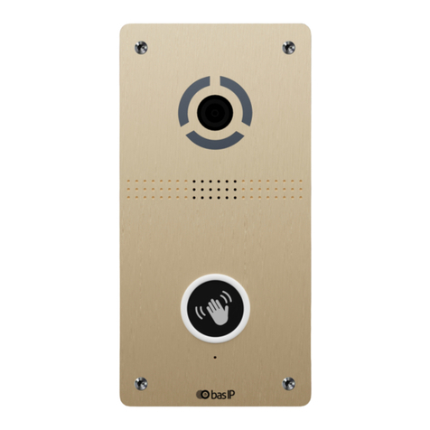
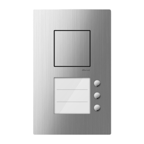
Entryphone 500 Series Quick start guide

DOOR ENTRY SYSTEMS
®
Entryphone
The Entryphone Company Limited,
23 Granville Road,
London, SW18 5SD
t: 020 8870 8635 f: 020 8874 0066
®ENTRYPHONE is a trade mark registered in Britain No. B1037141.
500 Series Video
Schematics, connection diagrams and installer's notes
For the system installed at:
By:

Door Release.
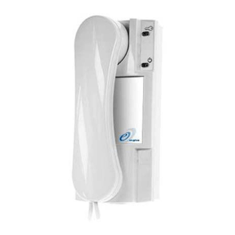
Telephones
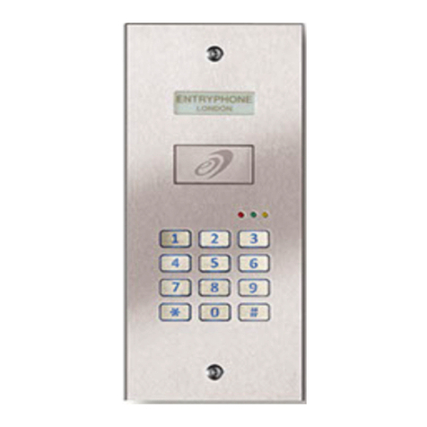
Multi-button Entrance
Unit.
DIP Switch
Setting
Power Supply
Relay Unit
Jumper Setting
Remote Camera
see pages 4/5 and
12/13
Single button
Entrance
Unit
Extension
Sounder
see pages 4/5
4 Way Splitter
Timeswitch
see pages 6/7
12345 6 7 8
0 3
ON
Entryphone®page 2
Contents
Page
Important 3
Schematic and connection diagrams - examples
One line system - looped wiring 4
Three way system - single run wiring 6
Six-way system - two riser looped wiring 8
Multi-door system using 500DCU door capture relays 10
Panel connections 12
Phone binary codes 14
Installer's notes 15

DIP Switch set to
address no.6
Jumper (J1) on Jumper (J1) o
Entryphone 500 Series equipment is designed to enable video systems to be installed on
standard audio wiring. The video, speech, signalling and power are on ve common conductors
to every part of the system.
There are two very important things that must be done to ensure a system works well.
1. The video signal is balanced and therefore termination jumpers must be inserted at line
ends or removed from mid-line equipment.
Schematics and wiring diagrams show when jumpers should be tted.
NOTE: If, on test, a video screen seems over bright or washed out it is likely that the line
has not been terminated properly, either a jumper is inserted mid-line or missing at the
end of the line.
2. There are no individual call lines for the 500 series systems, instead each phone has a
switch setting that should be set when the telephone is installed.
The phone's address is set as a binary number on an eight way DIL (dual in-line) switch
(up to 255 addresses available) tted in each phone. When planning a system it is good
practice to determine which address is to be assigned to which phone and noted on the
numbering sheet on page 14 of these instructions.
System Layout
Whether installing a system on existing or new wiring it is best to determine the layout of the
cabling and positions of the apparatus before starting the installation. There are a number of
layout examples and their corresponding connection diagrams in this booklet.
Please make a note of the phone codes and sketch the layout of the system on pages 14 and 15
of this booklet. Leave this booklet with the installed system.
Entryphone®page 3
Important

2
7
5
5
5
1
ON
234
5 6
7 8
0 1
1
ON
2345 6 7 8
0 1
1
ON
2345 6 7 8
0 1
2
3
J2V Link (see notes)
Entryphone®page 4
System Description
One line system - looped wiring
A one-way system with two parallel
phones with wiring looped from
phone to phone.
Second camera: There is an option
to t a second camera to the system.
The camera should be connected
to the 2nd camera terminals on
the door amplier printed circuit
board (see page 12/13) and link J2V
should be inserted. When the J2V
link is inserted the cameras switch
over every two seconds. The camera
button on the phone will switch
between cameras or lock view to
one camera.
Single button panel's call address is
set to 01.
Schematic

GRN/
WHT
1 Video -
WHT/
GRN
2Video +
BLU/
WHT
3Data
WHT/
BLU
424V-
ORG/
WHI
524V+
BRN/
WHT
6 Lock Data +
WHT/
BRN
7 Lock Data -
Key: line function
12345123451D 2D 3D 4D 5D 6D 7D 24V0V
OUT 1 OUT 2 DOOR UNIT AUX PSU
NO Com NC 0V12V
AC Output
LOCK RELAY
DOOR
MONITOR
J1
PSU
12345 R- R+
1D 2D 3D 4D 5D 6D 7D12 0 V
12345 R- R+
12345 R- R+
CAM 2
ENTRANCE PANEL
Extension sounder
12vDC Max 300mA
Second camera
12vDC Max 300mA
TEL3
TEL2
TEL1
Lock Release
12 0 V
+ -
~ ~
Entryphone®page 5
Connections

2
9
5
5
5
12345 6 7 8
0 2
ON
12345 6 7 8
0 3
ON
3
1
ON
ON
2345 6 7 8
0 1
Entryphone®page 6
System Description
Three way system - single run wiring
A three-way system with wiring in
single runs from the power supply
to each phone.
Trades time-switch allows access at
preselected times via a button on
the entrance panel.
Note: In this example the link in the
power supply is removed as the
input terminals are mid-line.
Schematic

GRN/
WHT
1 Video -
WHT/
GRN
2Video +
BLU/
WHT
3Data
WHT/
BLU
424V-
ORG/
WHI
524V+
BRN/
WHT
6 Lock Data +
WHT/
BRN
7 Lock Data -
Key: line function
TEL3
TEL2
NOTE:
Termination links
in for line end
NOTE:
Termination link
removed for
mid line
TEL1
PSU
ENTRANCE PANEL
Lock Release
Time-switch
12345123451D 2D 3D 4D 5D 6D 7D 24V0V
OUT 1 OUT 2 DOOR UNIT AUX PSU
NO Com NC 0V12V
AC Output
LOCK RELAY
DOOR 1
MONITOR
12345
1D 2D 3D 4D 5D 6D 7D12 0 V
12345
12345 R- R+
CAM 2
~ ~
J1
NC NO -+
AC/DC
CO
Entryphone®page 7
Connections

Entryphone®page 8
2
5
5
5
5
4
5
5
5
12345 6 7 8
0 1
ON
12345 6 7 8
0 2
ON
12345 6 7 8
0 4
ON
12345 6 7 8
0 6
ON
12345 6 7 8
0 3
ON
12345 6 7 8
0 5
ON
Schematic
System Description
Six-way system - two riser looped
wiring
A six-way system with wiring in two
legs from a splitter to three loop
wired phones. Jumpers are removed
in mid-line apparatus.
Note: In this example the power
supply is in a dierent location to
the splitter. If they were in the same
place no splitter would be required.

GRN/
WHT
1 Video -
WHT/
GRN
2Video +
BLU/
WHT
3Data
WHT/
BLU
424V-
ORG/
WHI
524V+
BRN/
WHT
6 Lock Data +
WHT/
BRN
7 Lock Data -
Key: line function
Entryphone®page 9
Connections
12345123451D 2D 3D 4D 5D 6D 7D 24V0V
OUT 1 OUT 2 DOOR UNIT AUX PSU
DOOR
MONITOR
12345
1D 2D 3D 4D 5D 6D 7D12 0 V
CAM 2
J1
12345
12345
24V 0V 54321
SPLITTER
500VS4
12345
12345
12345
12345 12345
12345 12345
NO Com NC 0V12V
AC Output
LOCK RELAY
~ ~
TEL1
TEL3
TEL5
TEL2
TEL4
TEL6
Lock Release
ENTRANCE PANEL
PSU
NOTE:
Termination links
in for line end
OUT 1
OUT 3 OUT 4
IN
OUT 2

Entryphone®page 10
Schematic
5
5
5
5
55
77
22
7 7
0 1 0 2
04
06
12345 6 7 8
ON
0 3
12345 6 7 8
ON
0 5
12345 6 7 8
ON
5
12345 6 7 8
ON
12345 6 7 8
ON
12345 6 7 8
ON
System Description
Multi-door panel video system
using 500DCU door capture
relays.
The 500DCU relay unit enables
any number of door panels to be
tted on a system.
When a button is pressed on any
door panel the relay switches
the circuitry on in that panel and
sends a signal to turn o the
other panels.
The system shown is a two door
six-way system with wiring in
two legs from the power supply/
splitter i.e. two runs of three
loop wired phones from the two
phone outputs in the power
supply. The diagrams here show
just two doors served but the
DCU can be daisy-chained for
additional panels.
Termination links (jumpers)
must be removed in mid-line
apparatus.

GRN/
WHT
1 Video -
WHT/
GRN
2Video +
BLU/
WHT
3Data
WHT/
BLU
424V-
ORG/
WHI
524V+
BRN/
WHT
6 Lock Data +
WHT/
BRN
7 Lock Data -
Key: line function
Entryphone®page 11
Connections
1B 2B 3B 4B 5B RB 1L 2L 3L 4L 5L 6L 7L 1F 2F 3F 4F RF
5F
FROM OTHER DCU
DOOR 1
MONITOR
J1
NO Com NC
0V12V
AC Output
LOCK RELAY
LOCAL DOOR UNIT
TO PHONES OR NEXT DCU
12345
+ -
24V DC IN LOCAL PHONES ONLY
1B 2B 3B 4B 5B RB 1L 2L 3L 4L 5L 6L 7L 1F 2F 3F 4F RF
5F
FROM OTHER DCU
DOOR 1
MONITOR
J1
NO Com NC
0V12V
AC Output
LOCK RELAY
LOCAL DOOR UNIT
TO PHONES OR NEXT DCU
12345+-
24V DC IN LOCAL PHONES ONLY
1D 2D 3D 4D 5D 6D 7D12 0 V
CAM 2
12345
12345
24V0V
54321
12345
12345
12345123451D 2D 3D 4D 5D 6D 7D 24V0V
OUT 1 OUT 2 DOOR UNIT AUX PSU
J1
1D 2D 3D 4D 5D 6D 7D12 0 V
CAM 2
12345 12345
12345 12345
12345 12345
DOOR 1
MONITOR
NO Com NC 0V12V
AC Output
LOCK RELAY
~ ~~ ~
LOCK 2
LOCK 2
LOCK 2
TEL1TEL1TEL1
TEL1 TEL1 TEL1
SPLITTER
500VS4
OUT 1
OUT 2
IN
OUT 4
OUT 3
DOOR CAPTURE UNIT
500DCU
DOOR CAPTURE UNIT
500DCU
PSU
ENTRANCE PANEL ENTRANCE PANEL
Lock Release Lock Release
NOTE:
Termination links
in for line end

Entryphone®page 12
Panel connections
500 series entrance panels are
supplied with the 500LSV loud-
speaking amplier assembly tted
and the call buttons are pre-wired.
It is not necessary for the installer
to change the button wiring. The
call buttons are connected using
a 7x7 matrix conguration which
is detailed here. Rather than
change the panel button wiring an
installer should consider changing
the phone address.
*Note: Option links and intercom
mode are reserved for systems not
covered by this booklet.
Button matrix
output pins
(see gs.1&2)
*Option Links
3&4 for always on
1&3 Divert to 1
2nd Camera
input
(see g.7)
Camera angle
adjustment
gimbal assembly
Button back
lighting voltage
(see g.3)
*Intercom mode
(Plan2)
connector
Panel camera
input
(see g.6)
Mic connector
(see g.5)
Speaker
connector
(see g.4)
2nd Camera
Jumper - J2V
Ring feedback
volume
inter-equipment
connector
Call buttons
CPB
(common bell push)
back-lighting
connection
(see g.3)
Mic sensitivity
Speaker volume
Lock release
time

Entryphone®page 13
Panel connections
Fig.1
Matrix connection to buttons
1- 11 shown
1234567 8
0 1
1234567 8
0 2
1234567 8
0 3
1234567 8
0 4
1234567 8
0 5
1234567 8
0 6
1234567 8
0 7
1234567 8
0 8
1234567 8
0 9
12345 6 7 8
1 0
1234567 8
11
Fig.6
Panel camera
+ -
V
Fig.5
Microphone
+ -
Fig.4
Speaker
+ -
Fig.3
Back-lighting
(note wired in series)
Fig.7
2nd Camera
12 V0
Fig.2
Matrix connection numbers 1-49
41
2
3
4
5
6
7
8
9
10
11
12
13
14
5
6
7
8
9
1
0
1
1
1
2
1
3
1
4
1
5
1
6
1
7
3
2
1
15
16
17
18
19
20
21
22
23
24
25
26
27
28
29
30
31
32
33
34
35
36
37
38
39
40
41
42
43
44
45
46
47
48
49

Entryphone®page 14
Phone binary codes
1234567 8
1234567 8
1
1
2
2
3
3
4
4
5
5
6
6
7
7
8
8
1234567 8
1234567 8
1234567 8
1234567 8
1234567 8
12345 6 7 8
12345 6 7 8
1234567 8
12345 6 7 8
12345 6 7 8
12345 6 7 8
01
02
03
04
05
06
07
08
09
10
11
12
13
14
15
1234567 8
1234567 8
1
1
2
2
3
3
4
4
5
5
6
6
7
7
8
8
1234567 8
1234567 8
12345 6 7 8
12345 6 7 8
12345 6 7 8
1234567 8
1234567 8
1234567 8
1234567 8
1234567 8
1234567 8
16
17
18
19
20
21
22
23
24
25
26
27
28
29
30
12345 6 7 8
12345 6 7 8
1
1
2
2
3
3
4
4
5
5
6
6
7
7
8
8
12345 6 7 8
12345 6 7 8
1234567 8
1234567 8
1234567 8
12345 6 7 8
1234567 8
1234567 8
12345 6 7 8
12345 6 7 8
12345 6 7 8
31
32
33
34
35
36
37
38
39
40
41
42
43
44
45
ON
It is good practice to decide the layout of the system and the allocation of phone codes
before starting an installation. Use the list below to indicate which code is assigned
to which phone. Bear in mind the positions of the number or names on the entrance
panel.
To work out the decimal value of the binary code add the decimal
values of each switch together. This example shows switches 2
(binary value 2), 4 (binary value 8) & 5 (binary value 16) down.
Therefore 2+8+16 = 26.
1234567 8
26
16
32
64
128
8
4
2
1
Binary Value
ON

Entryphone®page 15
Installer's notes

DOOR ENTRY SYSTEMS
®
Entryphone
The Entryphone Company Limited,
23 Granville Road,
London, SW18 5SD
t: 020 8870 8635 f: 020 8874 0066
®ENTRYPHONE is a trade mark registered in Britain No. B1037141.
Other manuals for 500 Series
1
Table of contents
Other Entryphone Intercom System manuals
