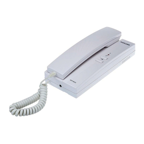
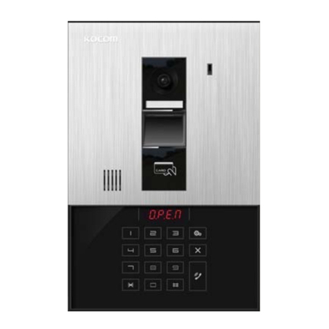
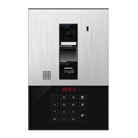
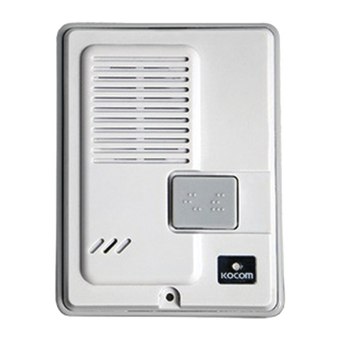
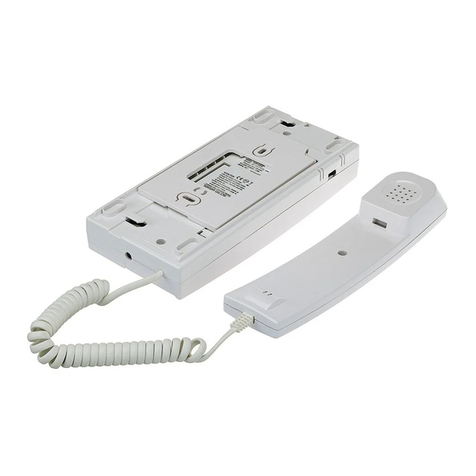
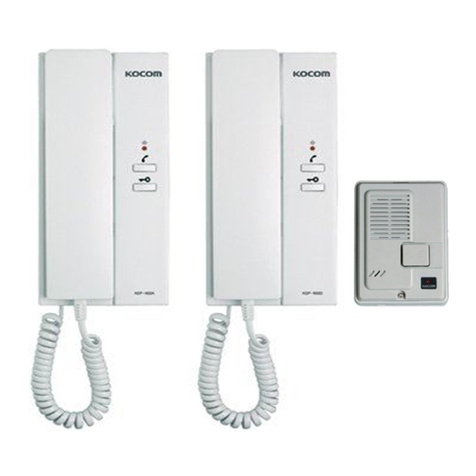
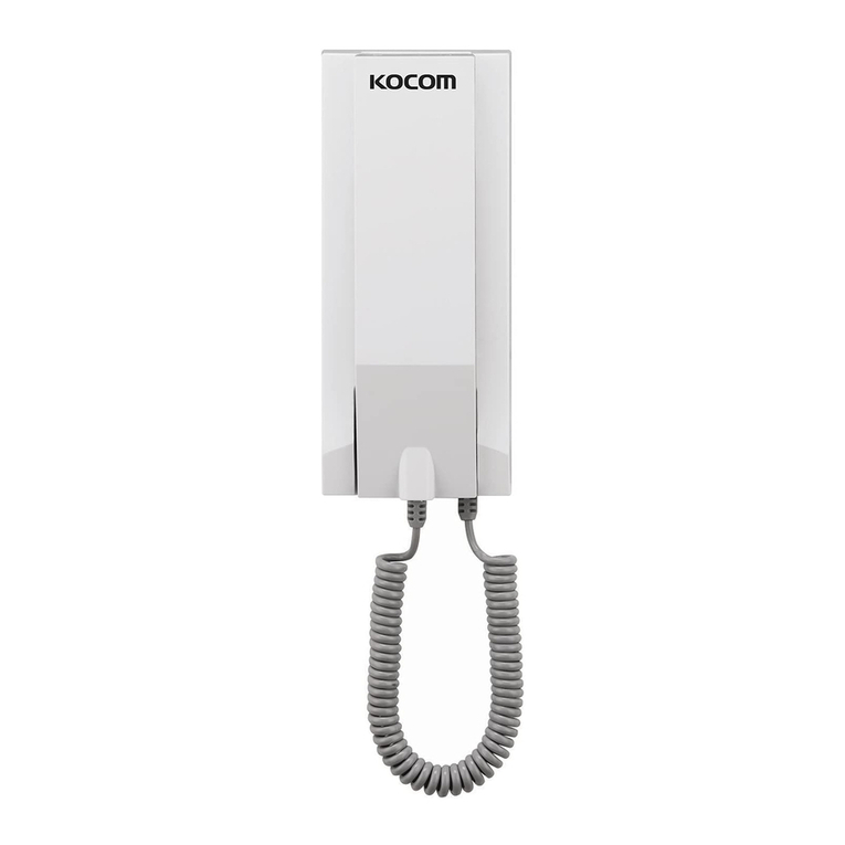
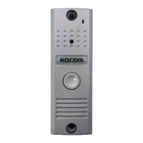
KOCOM KLPD410 Instruction Manual

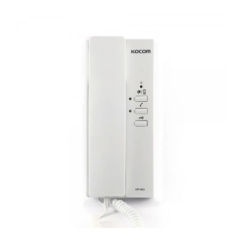
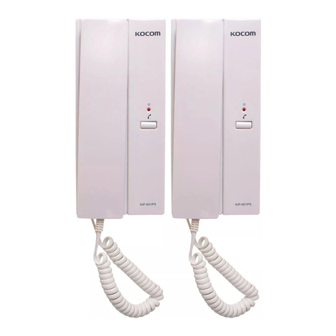
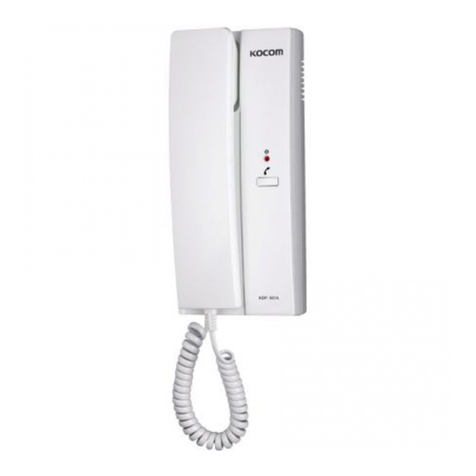
KIP-603 User’s Manual for Operation and Installation
Connection up to 2 units of monitors and inter phones, respectivel
Lobb chime switch function
Lobb door open/close after communication with lobb phone
Inner line (video phone and interphone) call and communication
Call to and communication with guardroom (KIP-603)
Interphone
for Apartment Unit
PRODUCT
MODEL
DATE PURCHASED
WARRANTY PERIOD
AGENCY ADDRESS
KOCOM Warranties the original purchaser of this product
as follows.
1) This product is produced under strict qualit control and inspection procedures.
2) If this product breaks down during proper use as a result of product defect, KOCOM
will repair it within one ear from date of purchase free of charge.
3) The following cases will be subject to charge, even during warrant period:
a. Breakdown during transport, or through careless treatment, b consumer.
b. Breakdown cause b unauthorized repair, or s stem modification.
c. Breakdown caused b natural disaster or power disorder.
Warranty
Warranty Card
KIP-603 04.04
To receive after-Sale service, have the following ready
when you contact our branches
1. Name of the product
2. Model number of the product
3. The area of problem
4. Phone number and address at
which ou can be contacted.
This manual is based on the date as shown in the right and specifications
are subject to change without notice for qualit improvement.

Place bracket on the wall and fix it
with screws. After wiring, fit the rear
side of main frame to a groove in the
bracket and pull the main frame down
to fix.
Avoid connection after wiring.
Product Specification
External Wiring Diagram
ower:
Common ower Input
Consuming Electricity
Guaranteed Operation Temperature
Communication Mechanism
Melody
Wiring
Wiring Distance
Dimensions
Max 1W (standb mode) / Max 2.5W (operation mode)
Balance Circuit
(front door, inner lines, guardroom, lobb )
5-line polar wiring
/Voice 1/Voice 2
Chime
within
Chime
with in 30m
W
H
Precautions for Wiring
As incorrect wiring ma cause the device’s non-operation or poor communication qualit , please
carefull conduct wiring work.
When connecting a wiring chord to a terminal, loosen screw, insert the end of the chord into the bottom
part of screw, and tighten the screw.
When fixing wiring chord, use stapler not to cause damage to the chord.
When using existing wiring, please be cautious not to cause disconnection and short-circuit.
Power Lamp (Green)
Internal Call button
Door Open Button: Pressing the button after
communication with lobb , opener installed
lobb door is opened.
Guard/Lobb Button: Used in call to guardroom,
conversion to communication with guardroom, or
communication after call from lobb
3-Level Volume Switch
Guard/Lobb (Green)
Inner Lines (Yellow)
Instructions for Installation
Component’s Name
Keep awa from humidifier
and stove. High temperature
and humidit ma cause
troubles.
When cleaning, do not use wet hand,
volatile benzene or paint thinner.
Use soft cloths dipping in neutral
detergent to wash this device and dr
it with dr clothes.
As this device consists of electronic precision components, do not attempt to
disassemble.
Do not drop this device
and avoid strong impact.
Precautions for Operation
Clean the exterior of this device
with soft cloths at times to keep
it in clean state.
B
E
N
Z
E
N
E
T
H
I
N
N
E
R

■Inner line call to the newl installed house
�Picking up handset and pressing (inner line) button, newl installed
house is called out (call maintains for 30 seconds).
�Inner line LED is turned on (onl if there’s no house on inner line).
�Newl installed house responds to the call, call maintains (for 3 minutes).
(LED is turned off.)
�Hanging up handset, communication is ended.
■Inner line call from newl installed house
�If house received a call, tone sound rings in house handset (for 30 seconds)
�(inner line) LED flickers.
�Picking up handset, communication begins (maintains for 3 minutes).
(When communication begins, LED is turned off).
�Hanging up handset, communication is ended.
Call from guardroom to house
Call to guardroom for communication
Operational Description
Pressing chime switch to call, chime tone of call from front door rings
(device does not support communication function and onl detects call state).
Inner line call and communication ‐chime tone of inner line call rings and communication maintains
for 3 minutes (installation of additional monitors and interphones is required).
Communication with lobb phone ‐After chime tone rings, user can communicate with lobb phone
for 3 minutes. (If pressing the door open button during the communication with lobb phone, opener
installed common lobb door is opened.)
Call to and communication with guardroom
If pressing guard button on interphone, user can call to and communicate with guardroom.
�When a lobb calls to house in standb mode, tone sound rings for about 30 seconds in house.
�Speaker outputs tone sound and (lobb /guard) LED flickers.
�Picking up handset, communication with lobb is automaticall available
(available communication time: 3 minutes) (At this time, LED is turned off.)
�To open the door during the communication wit lobb , press door open button and opener will
automaticall operate.
�Hang up handset, communication is ended (call to lobb function is not available).
�If picking up handset and pressing guard/lobb button,
guardroom is called out (call maintains for 30 seconds).
(When other house is not on the line, LED is turned on.)
�If guardroom responds to the call, call state is maintained (for 3 minutes).
(When communication begins, LED is turned off.)
�If guardroom calls to house, tone sound rings in handset of house (for 30 seconds) and (guard/lobb )
LED flickers. Picking up handset, communication begins (communication maintains for 3 minutes).
�At this time, LED is turned off.
�Hanging up handset, communication is automaticall ended.
■Call from lobb
�5-line polar wiring between wirings in main line of apartment unit
�6-line polar wiring between KVM-520 (monitor) and interphone
�2-line non-polar wiring in connection with chime switch at front door
�6-line polar wiring when installing more devices
Functional Specification
Wiring Specification
Inner line call and communication
Instructions for Operation (Model: KLP-100) Functional Specifications
Call to house
When a visitor calls to house using lobb phone, press house number.
> Pressing call button, call sound rings and house is called out.
> If the house responds to the call, communication maintains for 3 minutes.
(Pressing door open button during the communication, opener installed common front door is opened.)
> When communication is ended, device returns to standb mode.
Call from lobb phone to guardroom
Pressing “0”and call button on the lobb phone, guardroom is called and lobb ID is displa ed in
guardroom device.
> Communication with guardroom maintains (for 3 minutes). When communication is ended, device returns
to standb mode.
Password Change
(Password change function is onl available during the call with house.)
Pressing “# # 0 0 #”during the call with house,“______”is displa ed.
Input new password and press “#”button.
Door open using lobb phone with password
Pressing “house number + # + password + #”designated b the house, door is automaticall opened.
e.g. Press house number “1111”and password.
Model:
Call to house
1. Press the house number on the lobb phone.
(If pressing house number once more for call sound outputs, call is cancelled.)
As separate cancel button is not available on these devices, press house number once more to cancel the call.
2. With call sound rings, house is called.
(In the case of newl installed lobb phone, call from and communication with guardroom, or
(house is on the line, devices output absence melod and returns to standb mode.)
In the event that opener operates during the communication with house
1. If door open button is pressed at the house during the communication with lobb phone, common front
door is opened.
(Opener specification: within DC12V300mA - maintains 2 seconds)
Instructions for Operation

Numbers b the figure indicate the number
set when all switches move toward ON
direction.
1. Above figure, turning all DIP switches from No.1 to No. 12 toward ON direction, numbers set b DIP
switches are summed up.
e.g. 1) Above figure, turning switch No.1 and No. 2 toward On direction, value is set at 3 (1 + 2 = 3) since
numbers set b switches are 1 and 2.
e.g. 2) Above figure, turning switch No.1 and No. 3 toward On direction, value is set at 4 (1 + 3 = 4) since
numbers set b switches are 1 and 3.
e.g. 3)
e.g. 3)
e.g. 1)
e.g. 2)
1,000-digit
100-digit
1,10 -digit
DIP Switch Setting at House Interphone and Video Phone

3. If DIP switches are set as in the above example, press “8102”to call the house using guardroom master
or lobb phone.
In addition, house number is displa ed as small character “b102”in FND of guardroom master or lobb
phone.
4. Precautions for DIP Switch Setting (House No. Setting)
1) After setting DIP switches, device power should be reset.
(In ON state, DIP switches cannot be set.)
2) For setting basement floors, switch No. 11 and 12 should be ON state.
3) For direct dialing t pe lobb phone, up to 12 houses can be set.
Thus, when DIP switches of house interphone and video phone are set, available houses are also 1 to 12 in
number.
4) If user wants to use interphone or video phone as sub-phone, all DIP switches should be in OFF state.
5) When user sets DIP switches, excessive impact on DIP switches ma cause abnormal or erroneous
operation of device.
2. For basement floors, DIP switch No. 11 and 12 are generall set toward ON direction.
In this case, the value of DIP switch setting is 3,000 (1,000 + 2,000). However, program uses“8” with
similar shape of “B”(Basement) to indicate basement floors. Thus, value is not 3,000 but 8,000.
e.g. 4)
This manual suits for next models
1
Table of contents
Other KOCOM Intercom System manuals

KOCOM
KOCOM KCV-A374SD User manual

KOCOM
KOCOM KC-C60 User manual

KOCOM
KOCOM KIP-501PM Instruction Manual

KOCOM
KOCOM KCV-434SD Manual

KOCOM
KOCOM KOCKCVS701IP2W User manual

KOCOM
KOCOM KDP-602GD User manual

KOCOM
KOCOM KLP-1000 User manual

KOCOM
KOCOM KDP-Q81F User manual

KOCOM
KOCOM KCV-802R Manual

KOCOM
KOCOM KVM-340 Manual

KOCOM
KOCOM KDP-602A Instruction Manual

KOCOM
KOCOM KCV-352 / D352 User manual

KOCOM
KOCOM KIP-605PG Instruction Manual

KOCOM
KOCOM KVM-524GS Manual

KOCOM
KOCOM KC-C60 Manual

KOCOM
KOCOM KIP-300 User manual

KOCOM
KOCOM KLP-420 series User manual

KOCOM
KOCOM KVM-514GS Manual

KOCOM
KOCOM IP-201P Guide

KOCOM
KOCOM KVM-301 Manual