Enttec ALEPH 2 ET User manual

User Manual
Rev G / Firmware V1.6
Document PN: 50 78
For latest version please visit:
www.enttec.com
ALEPH 2
ET
6 C O L O U R H I G H P O W E R L E D L I G H T B A R
300mm/600mm/900mm/1200mm
Back Panel
Please make sure the Power pass-through current does not exceed 10 Amps
Features
•Strong aluminium chassis with small profile
•DM 512 Controllable and RDM Configurable
•Can use up to 12 DM channels, depending on
configuration
•Snapshots: 64 fully user recordable slots, 50
different pre-loaded stand-alone colours
•16-bit or Smart 8-bit LED dimming
•Strobe Mode with controllable frequency from DM
•Smart heat management
•Easy addressing and configuration interface
•180° Adjustable mounting bracket
•Changeable diffuser using holder accessory (sold
separately)
1
User Manual
Rev G / Firmware V1.6
Document PN: 50 78
For latest version please visit:
www.enttec.com
Cleaning
It is important to clean the ALEPH2 ET to maintain a
long service life. Make sure the unit is unplugged before
you attempt any cleaning.
•Surface dust should be removed with an air
compressor, please make sure you do not blow
compressed air directly onto the fan or inside
the unit.
•Optics can be cleaned with a glass cleaner or
IPA with a soft cloth
•Make sure the unit is dry and there is no
cleaning fluid residue before powering the unit
after cleaning.
Safety
•Do not expose this the ALEPH2 ET to rain or
moisture, doing this will void your warranty.
•Do not spill water or other liquids into or onto
your unit.
•Do not look directly into the LEDs, doing so may
damage your eyes.
•Check that the local power outlet matches that
of the required voltage (120 → 240V AC)
•Make all the connections before you plug in the
main power.
•Do not remove the cover under any condition.
There are no user serviceable parts inside.
•Never operate this unit when it’s cover is
removed.
•Never plug this unit in to a dimmer pack.
•Always be sure to mount this unit in an area
that will allow proper ventilation. Allow about 6”
(20 cm) between this device and a wall.
•Make sure ventilation holes are clean and
unobstructed.
•Do not attempt to operate this unit, if it
becomes damaged.
•This unit is intended for indoor use only, use of
this product outdoors voids all warranties.
•Always mount this unit in a safe and stable
manner.
•Power-supply cords should be routed so that
they are not likely to be walked on or pinched
by items placed upon or against them, paying
particular attention to the point they exit from
the unit and the hanger.
•The appliance should be situated away from
heat sources.
Main Menu
Press MENU key to enable the display, then UP or DOWN
Key to scroll through the top menu
adr tst snp per deg→ → → →
|----------------←---------------|
Press the MENU key to get in the desired mode.
The display will turn off when the buttons have not been
operated within a 15 seconds time-out whilst in one of the
top level menus: “adr”, “tst”, “snp”, “per” or “deg”; press
the MENU key to turn the display on when desired.
“adr” Menu
To see the current DM start address press the MENU key
when displaying “adr”, by default the light will show “001”.
To change the start address press MENU once more; the
cursor indicated by the “.” (dot) will appear on the digit to
be changed using the UP or DOWN keys. To move the
cursor to the new position press MENU again. Once you
have selected the last digit the menu will prompt you to
save the new address “YES” Press MENU again to save or
scroll “UP” or “DOWN” to display “NO” and press MENU to
cancel.
“tst” Self Testing Menu
To use the testing functions press the MENU key when
displaying “tst” and scroll through the test menu using the
UP or DOWN keys. The LEDs and fan will turn on as you
scroll. Press the MENU key to go back to the top menu.
ch1 ch2... ch6 all fan→ → →
|------------←----------|
“snp” Snap-Shots Menu
To use the pre-recorded snapshots, press the MENU key
when displaying “snp” and “001” will be shown. Then use
the arrow keys to navigate through the pre-loaded colours.
Please note that any incoming DM data will overwrite the
snap-shots, so ensure that there is no DM data coming in
before navigating this menu.
2
Display Function
Ch1 – ch6 Test channels 1 to 6
all Test all 6 Channels
fan Test Fan
Display Function
adr DM Address
tst Self Test
SNP Snap-Shots
per Personality
deg Temperature

User Manual
Rev G / Firmware V1.6
Document PN: 50 78
For latest version please visit:
www.enttec.com
The following Snap-Shots are pre-recorded in the unit:
Slots 051 to 064 are also pre loaded with High
luminance Natural White as per slot 050.
It is also possible to record user personalised Snap-
Shots on any of the 64 memory slots, overwriting the
default ones.
To record your own Snap-Shots please scroll to the
desired slot (from 001-064), then press the “MENU” key
to enable the editing mode indicated by the “.” (dot).
Once you are in editing mode please feed the desired
data through DM port and press “MENU” again when
you are happy with the output; finally select “yes” or “no”
to finalise.
Please note that when the light is powered on, it will
automatically take Snap-Shot 001 as the default power
on value. This feature is handy for the user to set up the
desired colour combination for the fitting to start every
time it is powered up.
Please note that the strobe feature is not a supported
Snap-Shot.
Running the Factory Defaults RDM command will restore
all the snap-shots to the original values and user
recorded snap-shots will not be recoverable.
“per” Personality Menu
To see the current personality press the MENU key when
displaying “per”, by default the light will show “001” as this
is the factory setting.
To change the personality press MENU again; the cursor
indicated by the “.” (dot) will appear on the last digit where
you can select one out of the three available personalities
using the UP or DOWN keys. Press the MENU key and it will
prompt you to save the new address showing “YES” Press
MENU again to save or scroll “UP” or “DOWN” to display
“NO” then press MENU if you want to cancel.
Please refer to Operation Modes section to see a detailed
description of each personality.
“deg” Temperature Menu
To show the current temperature press the MENU key
when displaying “deg” and the display will show the current
fixture temperature in degrees Celsius. Press the MENU
key to go back to the top menu.
Operation Modes (Personalities)
The Aleph2 ET has three different personalities which can
either be selected remotely from any standard RDM
controller tool or locally using in-built menu. The light
behaves different on each mode, since the DM channel
distribution changes according to the desired working
personality. The modes are described bellow.
8BIT 6CHANNEL PERSONALITY (FACTORY DEFAULT)
This basic mode will allow you to drive each colour using 8
bits resolution, setting the values from one of the 6 DM
channels where 000->OFF, 255->Full intensity, as
described in the following chart.
E.g.#1 to turn all the channels to full intensity, set all the
channels to 255 value:
001 026 Cool Grey
002 Red 02 Ceil
003 Green 028 Sky Blue
004 Blue 029 Turquoise
005 Amber 030 Aquamarine
006 Cool White 031 Clover
00 RGB Yellow 032 Mint
008 RGB Purple 033 Dark Pastel Green
009 RGB Cyan 034 Pistachio
010 2000K White 035 Lawn Green
011 2500K White 036 Lime
012 3000K White 03 Pear
013 038 Apple Green
014 4000K White 039 Lemon
015 5000K White 040 Corn
016 041 Golden Yellow
01 6000K White 042 Pumpkin
018 Bubble Gum 043 Carrot Orange
019 Carmine 044 Khaki
020 Pink 045 Ochre
021 Pink1 046 Salmon
022 Pastel Violet 04 Coral
023 Dark Violet 048
024 Lavender 049
025 Lavender Blue 050
Snap
Shot
Factory Default
Colour
Snap
Shot
Factory Default
Colour
All channels OFF
(Default on Start-Up)
3200K White
(Tungsten)
5600K White
(Video White)
Coquelicot
High luminance
Cool White
High luminance
Natural White
Display Function
001 8bit 6Channel mode
002 16bit 12channel mode
003 Extended 9channel mode
8 BIT 6-CHANNE PERSONA ITY (DEFAU T)
RED GROUP GREEN GROUP B UE GROUP AMBER GROUP WHITES GROUP* WHITES GROUP*
*White LEDS will respond to the greatest value out of CH5 and CH6
1st Channel 2nd Channel 3rd Channel 4th Channel 5th Channel 6th Channel

User Manual
Rev G / Firmware V1.6
Document PN: 50 78
For latest version please visit:
www.enttec.com
E.g.#2 to turn only the red group colour to full intensity,
set the first channel to 255 value:
The smart dimming in this personality follows an “s”
curve resulting in a smooth LED output all along the 8
bits range.
16BIT 12CHANNEL PERSONALITY
This mode will allow you to drive each colour using 16
bits resolution; setting the values from one of the 12
DM channels from 000 to 255 where the first channel
of each group will be (HIGH) and the following channel
the (LOW) one, as described in the following chart.
This personality gives the user full control on the output
dimming, so any colour combination can be generated.
E TENDED 9CHANNEL PERSONALITY
This extended mode offers a wide variety of output
effects, turning the Aleph2 ET into a very versatile unit,
using 9 DM channels, as described in the following
chart.
CO OUR GROUP INTENSITY (CH1-CH6) operate as
described in the 6-Channel personality plus they can be
modified or affected by the “strobe frequency” or
“Master dimmer channel” as described further in this
section. Although this 6 channels have no effect when
the “true CCT mode” is activated (9th channel > 010)
STROBE FREQUENCY (CH7) will turn the Aleph2 ET
bar into a versatile multi-colour strober with user
adjustable frequency.
The strobe feature can be activated by setting the
channel to a value between 011 and 252. Between the
same range, the strobe frequency can be adjusted by
varying the channel value, being 011 the lowest
frequency and 252 the highest one. Any other value
between 000-010 or 253-255 will stop the strobe
feature.
The strobe channel can be used in conjunction with all the
other channels, so you can change the current output
colour or the master intensity whilst strobing at the
selected frequency, all at the same time.
MASTER DIMMER (CH8) drives the general intensity,
merging with all other current output channels, being 000
the lowest intensity 0% (light will be OFF, regardless of
other channel values) and 255 the highest, allowing 100%
whatever other channels are demanding.
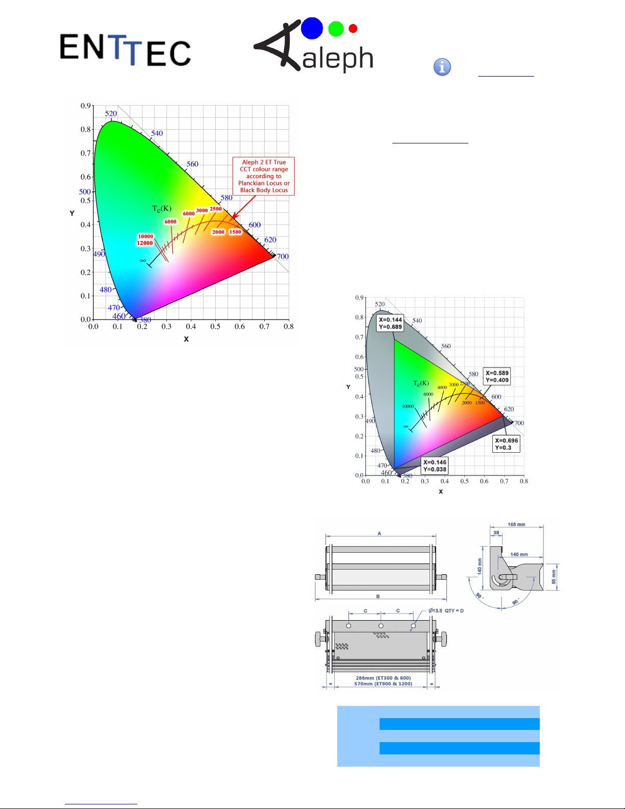
TRUE CCT MODE (CH9) will turn the Aleph2 ET bar into a
true colour temperature adjustable fitting, simulating a
tungsten light behaviour.
The white colour feature can be activated by setting the
channel to a value between 011 and 255. In this range, the
colour temperature can be adjusted by varying the channel
value, being 011 the warmest white and 255 the coolest
one. Values between 000-010 will stop the true CCT
feature.
The true CCT mode channel can be used in conjunction
with strobe frequency and master dimmer channels, so
you can strobe and/or dim the the current white output set
by this channel.
The Aleph2 ET has been laboratory calibrated to closely
follow the black body Locus curve along. With 8 bits
resolution allowing the light to travel from TRUE warm to
cool whites (12000K to 1800) keeping a high CRI for
natural colours.
4
16 BIT 12-CHANNE PERSONA ITY
*White LEDS will respond to the greatest combined value out of CH9 to CH12
1st Channel 2nd Channel 3rd Channel 4th Channel 5th Channel 6th Channel
RED GROUP
(HIGH)
RED GROUP
( OW)
GREEN GROUP
(HIGH)
GREEN GROUP
( OW)
B UE GROUP
(HIGH)
B UE GROUP
( OW)
7th Channel
8th Channel
9th Channel
10th Channel
11th Channel
12th Channel
AMBER
(HIGH)
AMBER
( OW)
WHITES
(HIGH)
WHITES
( OW)
WHITES
(HIGH)
WHITES
( OW)
8 BIT 9-CHANNE EXTENDED PERSONA ITY
RED GROUP GREEN GROUP B UE GROUP AMBER GROUP WHITES GROUP WHITES GROUP
1st Channel
2nd Channel
3rd Channel
4th Channel
5th Channel
6th Channel
7th Channel
8th Channel
9th Channel
*White LEDS will respond to the greatest
Value out of CH5 and CH6
STROBE
FREQUENCY
MASTER
DIMMER
TRUE CCT
MODE
User Manual
Rev G / Firmware V1.6
Document PN: 50 78
For latest version please visit:
www.enttec.com
RDM Capabilities
The Aleph2 ET counts with RDM capabilities and you can
read/write them by using any standard RDM tool.
Alternatively the “ENTTEC RDM Controller” software can
be downloaded for free from ENTTEC website and be
used in combination with a Datagate MK2, USB PRO,
RDM USB PRO or a PRO MK2 DM widget.
The Aleph2 ET supported RDM parameters are:
Read only fields
•RDM Protocol Version
•Device Model ID
•Software Version ID
•Sensor Value (temperature)
•DM Footprint
•Sensor Count
•Manufacturer Label
•Supported Parameters Count
User configurable fields
•DM Personality
◦8 Bit 6-Channel Mode
◦16 Bit 12-Channel Mode
◦8 Bit 9-Channel Mode
•DM Start Address
•Identify Device
•Factory Defaults
Please note that DM Personality and DM Start
Address fields can also be configured from the menu
interface at the back of the light.
Firmware Update
Updating the firmware to the Aleph2 ET requires an
ENTTEC USB Pro or a Pro Mk2 widget plugged in to a PC
USB port and to the Aleph2 ET through a standard 5 pin
DM cable.
Please download and install the ET_Update_Firmware
application from www.enttec.com website, connect the
widget to the unit, power it up and run the application.
Whilst performing the updating process the display will be
turned OFF and fan will be fully ON for about 35 seconds.
Then the display should show “ADR” and the light goes to
its original state once the process has finalised.
To make sure the process has been successful and check
the firmware version, please look at the “Software Version
ID” field using an RDM tool such us “ENTTEC RDM
Controller” software which can be downloaded for free
from the ENTTEC website.
Colour Gamut
Dimensions
5
Item A B C D
300mm 341mm 406mm 100mm 3
600mm 641mm 706mm 200mm 3
900mm 941mm 1006mm 200mm 5
1200mm 1241mm 1306mm 250mm 5

User Manual
Rev G / Firmware V1.6
Document PN: 50 78
For latest version please visit:
www.enttec.com
Specifications
Due to continuous improvements and innovations of all
ENTTEC products, specifications and features are
subject to change without notice.
Ordering Information
ENTTEC PTY LTD ENTTEC AMERICAS
Head office: 17/5 Samantha Court 604A Cornerstone Ct.
Knoxfield VIC 3180 Australia Hillsborough NC 27278 USA
Tel: +61 3 9763 5755 Tel & Fax: (888) 454-5922
Fax: +61 3 9763 5688 email: [email protected]
www.enttec.com
6
Item 300mm 600mm 900mm 1200mm
Input Voltage 110 – 240V AC
Input Frequency 50/60Hz
Maximum Input Power 90 Watts 180 Watts 270 Watts 360 Watts
Light Output (all leds) 3100 lumens 6200 lumens 9300 lumens 12400 lumens
Lumens/Watt 34.44
CRI 90
CREE P-E Leds Quantity 30 60 90 120
Colours Red, Green, Blue, Amber, Cool White, Cool White
Lens Clear Acrylic
Beam Angle 25°
Control Input DM 512 & RDM E1.20
Personalities 3 different DM distributions: 6, 9 and 12 channels
Smart Dimming 14 bit internal dimming mapped to 8 bit S curve
Weight (Kg) 3.7 4.9 8.5 11
Weight (Pounds) 8.2 10.8 18.7 24
Cooling Method Low noise forced air
Ambient Temperature 5° to 50° C
Surface Temperature 67°C at steady state (full intensity output and Ta=45°C)
Protection Rating IP20
Connectors
Maximum Surface
Temperature
70°C
Error mode (10% output) enables if T>70°C recovers after 5°C drop
1x 5-Pin Male LR for DM input
1x 5-Pin Female LR for DM output
1x IEC C13/C14 IN/OUT Socket 10Amps for mains
Item Part Number
Aleph2 ET 300mm 73500
Aleph2 ET 600mm 73501
Aleph2 ET 900mm 73502
Aleph2 ET 1200mm 73503
A2 ET 600m Diffuser Holder 79370
Table of contents
Other Enttec Lighting Equipment manuals


Popular Lighting Equipment manuals by other brands

AQUASONIC
AQUASONIC DILUVIO installation guide

PR Lighting
PR Lighting Mega Colour 2500 product manual

Colorlight
Colorlight CL10 user manual

Behringer
Behringer EUROLIGHT LED DSL1 quick start guide

Milwaukee
Milwaukee REDLITHIUM USB ROVER 2114-21 instruction manual

Tomar
Tomar Spider Microbar instruction manual


