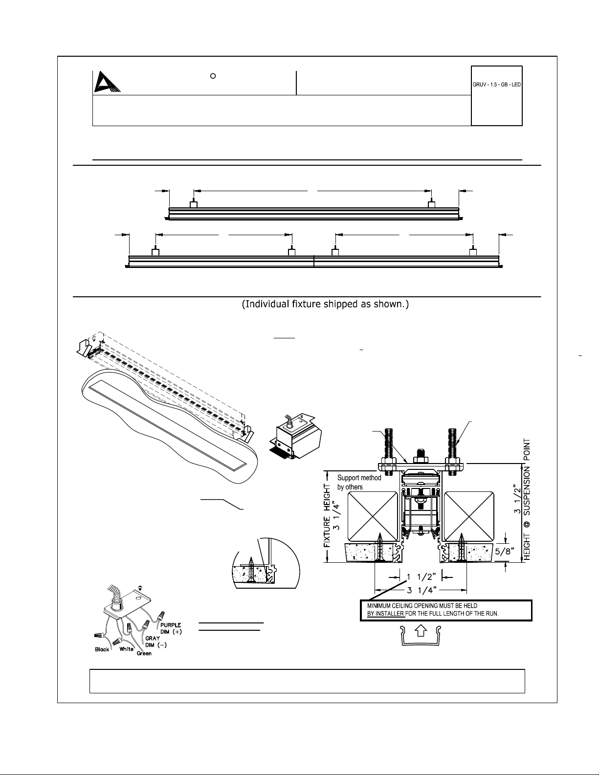
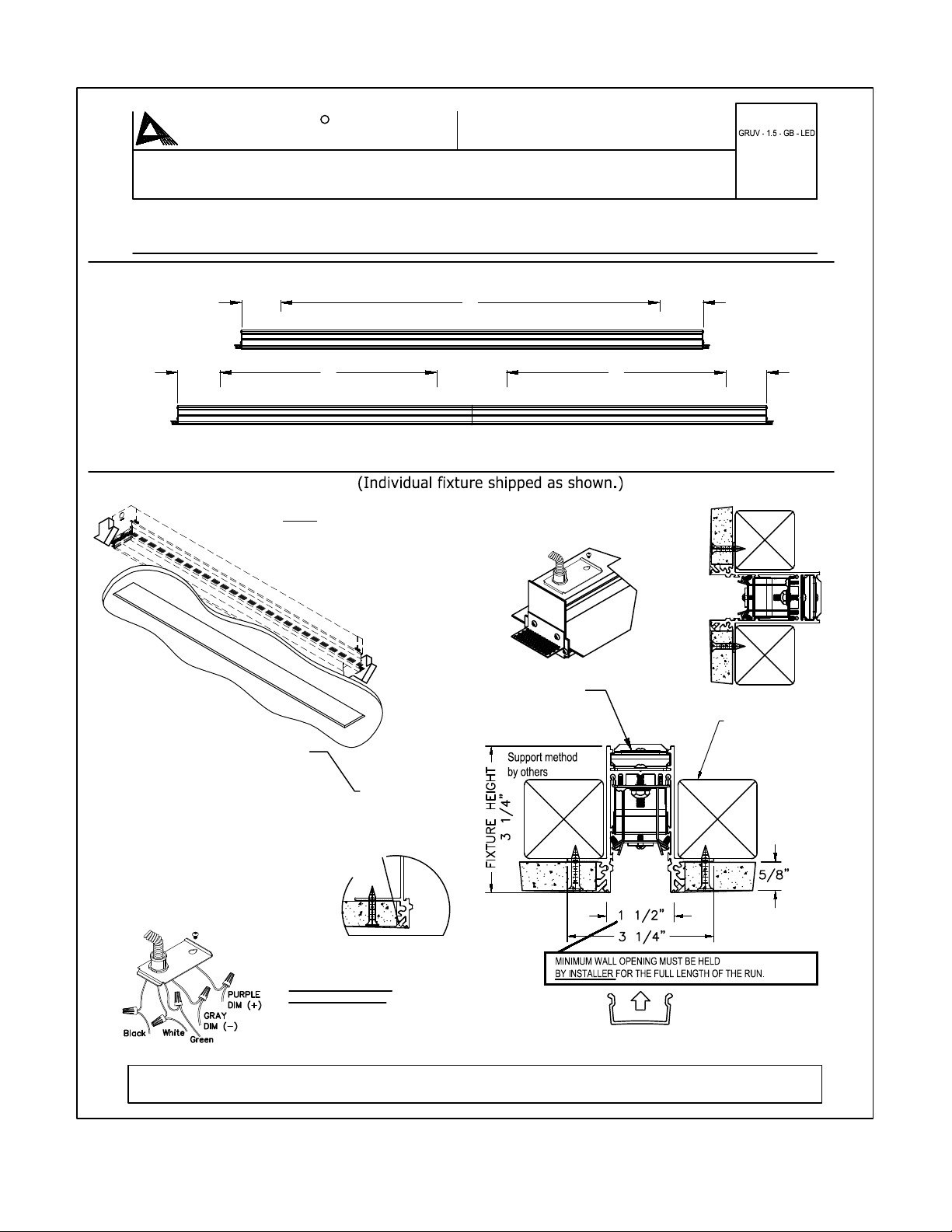
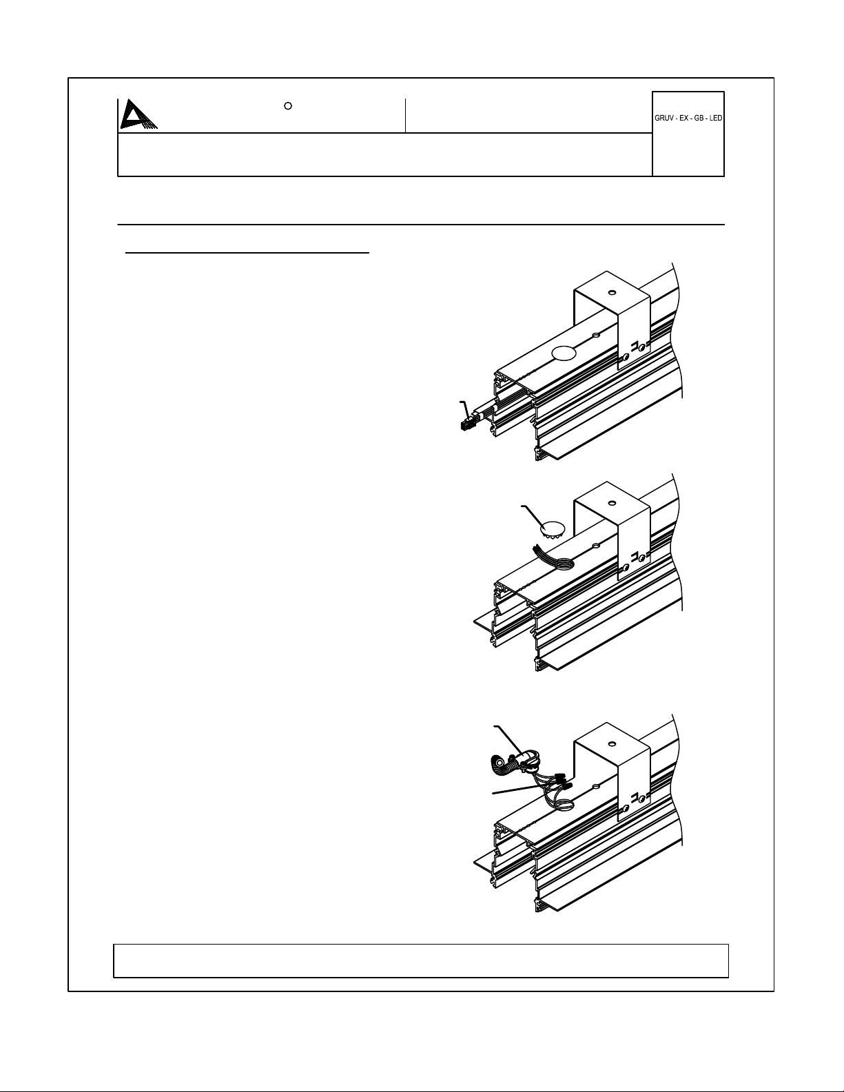
*: Fixture MUST be mounted before wall/ceiling is installed.
4. * Install wall (By Others)
5. Spackle in fixture.
6. Remove SHIPPING BRACE.
7. Snap-in LENS.
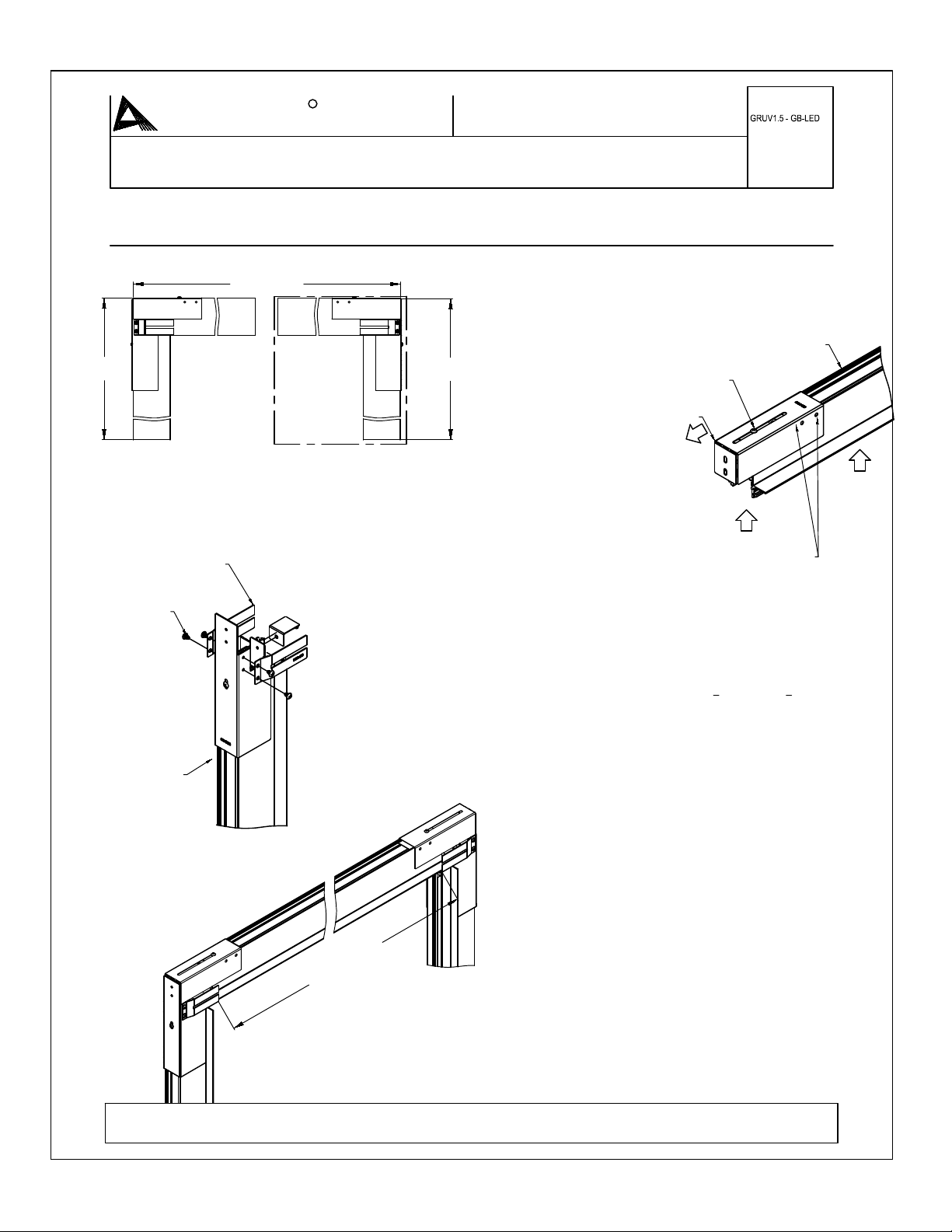
Wall/Ceiling Corner Installation
3. Install Horizontal fixture(s) closest
to corner.
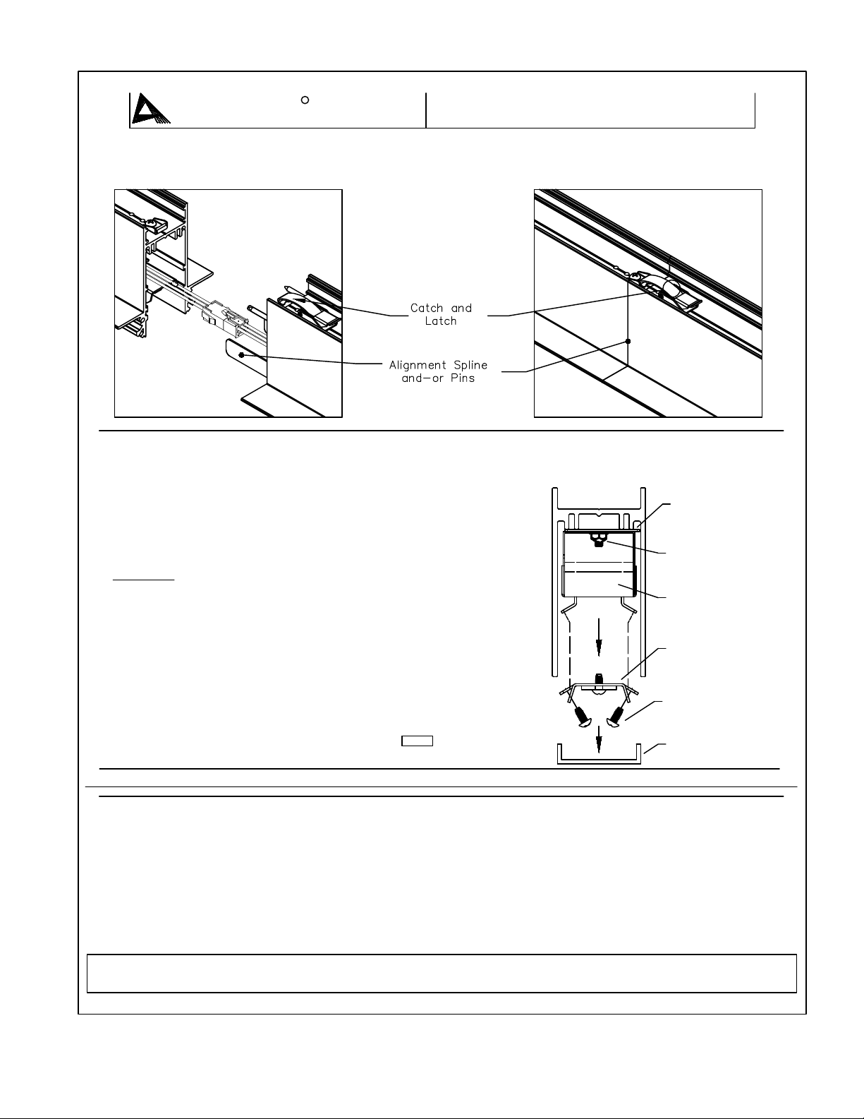
A. Lift fixture to ceiling. Connect wire
harnesses of the two fixtures.
B. Slide housing into corner cover, to
contact (Housing overlap min. of 1
4",
max. 3
4" at contact) Reference layout
drawing for location.
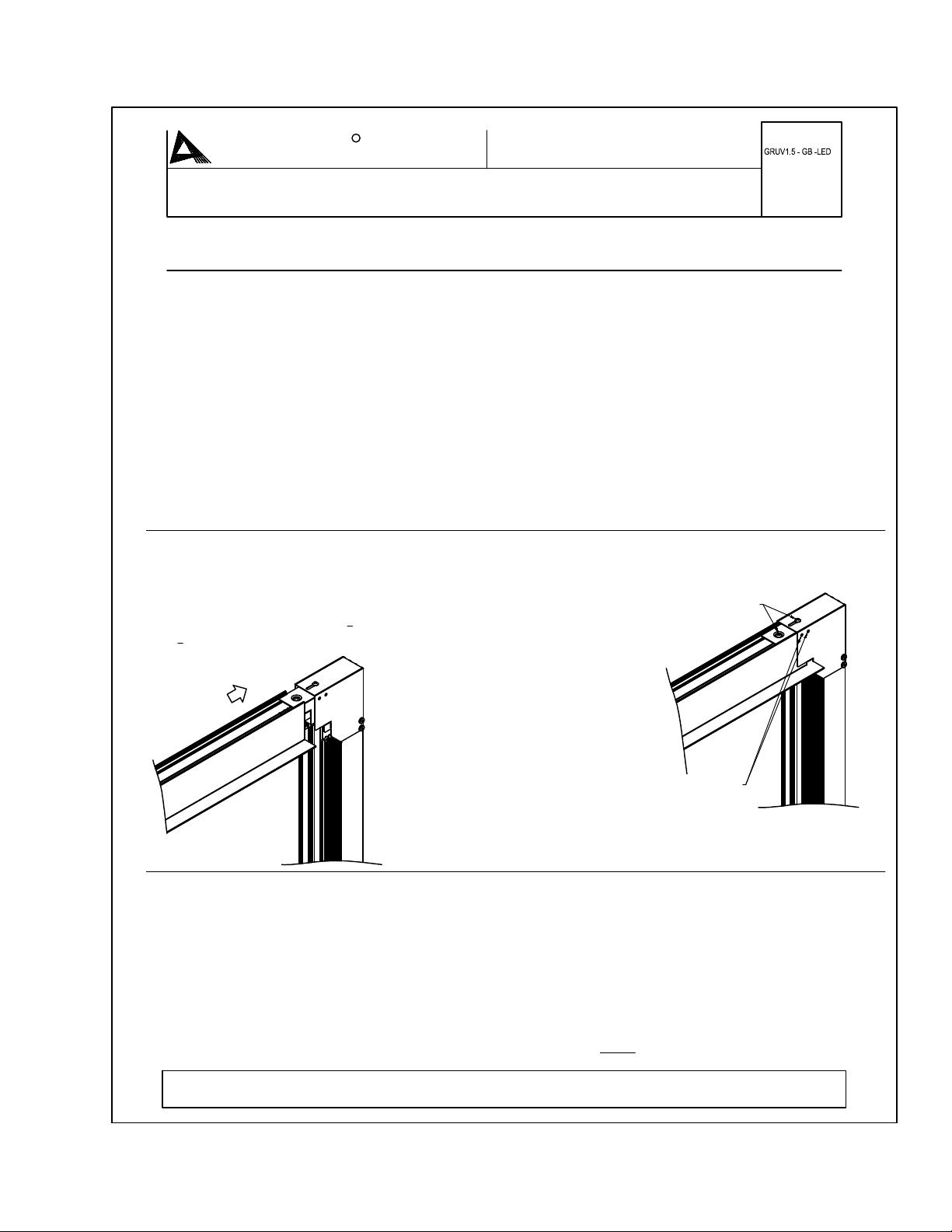
B. Loosen the top screw to the Top Bracket. Slide
Top Bracket to wall and tighten top screw.
C. (Option 1 ) Secure Top Bracket to vertical
Bracket with self drilling screw(By others)
D. (Option 2 ) Secure top screw on top Bracket
1. Install Vertical fixture(s) from the
ground up. Secure fixtures following
instructions from pages 1-3. Corner
fixture will already have corner cover
attached.
2. Once the fixture is secure, feed
power source through the knock-out.
Splice to harness according to code.
OPTIONAL SELF-DRILL SCREWS (2)
E. (Option 3 ) Install #8 X 3/8" self drilling
screw in the side holes of top bracket.
F. Secure fixtures following instructions
from pages 1-3.
TIGHTEN INTO PLACE
Amerlux, LLC. - 178 Bauer Drive, Oakland NJ 07436 - T: 973-882-5010 - F: 973-882-2605
www.amerlux.com
LIGHTING SOLUTIONS
AMERLUX ADAPT. ABILITY.
R
TM INSTALLATION INSTRUCTIONS
SHEET #:
WARNING - RISK OF FIRE AND ELECTRICAL SHOCK. FIXTURE MUST BE INSTALLED BY A QUALIFIED ELECTRICIAN
ONLY. FIXTURE IS INTENDED FOR INSTALLATION IN ACCORDANCE WITH THE NATIONAL ELECTRICAL CODE, LOCAL
AND FEDERAL SPECIFICATIONS. DISCONNECT POWER AT ELECTRICAL PANEL BEFORE SERVICING .
RETAIN THESE INSTRUCTIONS FOR MAINTENANCE REFERENCE.
SPEC. SHEET
REFERENCE:
689-0512 (4 of 5)
GRUV1.5-GB- LED - WALL/CEILING CORNER INSTALLATION (L-PATTERN)
Gyp Board