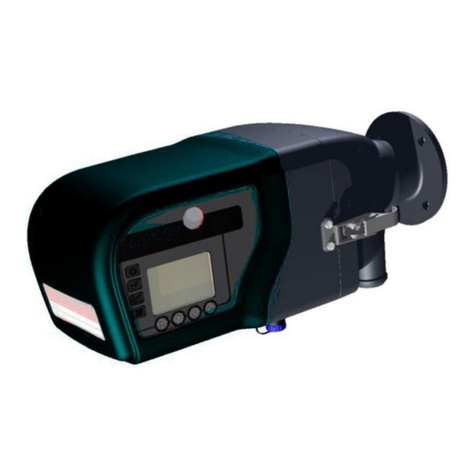
envea STACK 602 User manual

STACK 602
USER MANUAL


STACK 602
Particulate Measurement System
USER MANUAL
Publication Part Number: PC-000848-MA

Publication Part No. PC-000848-MA
Issue 5
December 2021
Original language: English
Copyright © ENVEA UK Ltd 2021
All rights reserved throughout the world. No part of this
document may be stored in a retrieval system,
transmitted, copied, or reproduced in any way, including,
but not limited to photocopy, photograph, magnetic or
other records without the prior agreement and permission
in writing of ENVEA UK Ltd.
Disclaimer
ENVEA reserves the right to revise and update this
documentation from time to time without obligation to
provide notification of such revision or change. Revised
documentation may be obtainable from ENVEA.
ENVEA reserves the right, without notice, to make changes
in equipment design or performance as progress in
engineering, manufacturing, or technology may warrant.
Trademarks
All product trademarks and registered trademarks are the
property of ENVEA UK Ltd.
All other product trademarks and registered trademarks
are the property of their respective companies.
envea™is a trademark of the ENVEA Group, France.
Feedback
ENVEA encourages customer feedback and welcomes
any comments or suggestions relating to the product or its
documentation.
Published by:
Technical Publications
ENVEA UK Ltd
ENVEA House
Rose & Crown Road
Swavesey, CAMBRIDGE
CB24 4RB, United Kingdom
Email: technicalpubli[email protected]

STACK 602
ENVEA UK Ltd (PC-000848-MA Issue 5, December 2021) v
Table of Contents
Table of Contents ............................................................................................... v
List of Figures ...................................................................................................vii
1. INTRODUCTION ____________________________________________ 9
1.1 Purpose of this Manual ............................................................................... 9
1.2 Product Safety .......................................................................................... 9
1.2.1 Danger from Process ......................................................................... 9
1.3 Safety Procedures ................................................................................... 10
1.4 Intended Use .......................................................................................... 10
1.5 Additional Information.............................................................................. 11
1.5.1 Product Serial Numbers ................................................................... 11
1.5.2 List of Abbreviations........................................................................ 11
1.5.3 Related Documentation ................................................................... 11
1.5.4 Product Parts and Options................................................................ 12
1.6Certification ............................................................................................ 12
1.6.1 Conformance and related Standards.................................................. 12
2. TECHNICAL DATA _________________________________________ 13
2.1 Process and Application Conditions ............................................................ 13
2.2 Sensor Specification................................................................................. 13
2.2.1 Dimensioned Drawings –Sensor Heads (Tx, Rx)................................. 14
2.2.2 Quality Assurance and Control.......................................................... 15
2.2.3 Sensor Options............................................................................... 15
2.3 System Options....................................................................................... 16
2.4 Cabling .................................................................................................. 16
2.4.1 Data Cable Specifications................................................................. 16
2.5PC Software Suite (PC-ME DUST TOOLS) .................................................... 17
3. PRODUCT DESCRIPTION ____________________________________ 18
3.1 System Overview .................................................................................... 18
3.1.1 Sensor –DynamicOpacity® Transmitter/Receiver............................... 18
3.1.2 Control Unit ................................................................................... 19
3.2 Principle of Operation............................................................................... 20
4. UNPACKING AND PREPARATION ______________________________ 21
4.1 Unpacking and Inspection......................................................................... 21
4.2 Network Layouts ..................................................................................... 21
4.3 Prerequisites and Guidelines ..................................................................... 21
4.3.1 Location Requirements .................................................................... 21
4.3.2 Cabling and Cable Routing ............................................................... 22
4.3.3 Grounding the Sensor ..................................................................... 22
4.4 Supplying Purge Air –Purge Blower Unit .................................................... 23
4.4.1 Mounting the Blower ....................................................................... 23
4.4.2 Connecting the Purge Blower............................................................ 24
4.4.3 Adjusting the Speed........................................................................ 25
5. SENSOR INSTALLATION ____________________________________ 26
5.1 Safety Information .................................................................................. 26
5.2 Mounting the Sensor................................................................................ 26
5.2.1 Transmitter and Receiver Heads ....................................................... 26
5.2.2 Assembling the Head Mounting Components (Tx/Rx)........................... 27
5.2.3 Fitting the Stack Mounting Stubs ...................................................... 28

STACK 602
vi (PC-000848-MA Issue 5, December 2021) ENVEA UK Ltd
5.2.4 Setting up the Air Purges ................................................................. 29
5.3 Connecting the Transmitter (Tx)................................................................ 29
5.3.1 Transmitter/Receiver Connections..................................................... 30
5.3.2 Transmitter/Receiver Link Settings ................................................... 30
5.4 Connecting the Receiver (Rx).................................................................... 31
5.4.1 Data Cable Connection .................................................................... 32
5.5 Setting up the Receiver ............................................................................ 33
5.5.1 Bus Termination Switch (SW101)...................................................... 33
5.5.2 Set Address Switch (SW201)............................................................ 33
5.5.3 Set Comms Settings (SW200) .......................................................... 34
6. BASIC SYSTEM SETUP ______________________________________ 35
6.1 User Controls and Functionality ................................................................. 35
6.1.1 The ProController UI ....................................................................... 35
6.1.2 The Standard Controller UI .............................................................. 36
6.2 ProController –Function Keys and Setup .................................................... 37
6.3 Main Menu Screens.................................................................................. 37
6.3.1 Other Symbols ............................................................................... 38
7. INITIAL SETUP ___________________________________________ 39
7.1 Introduction............................................................................................ 39
7.2 Power-up Checks..................................................................................... 39
7.2.1 Checking the Comms Mode .............................................................. 39
7.2.2 Performing a Master Reset ............................................................... 39
7.3 Adding Sensors ....................................................................................... 40
7.3.1 Detecting Devices Automatically (Autodetect) .................................... 40
7.4 Editing Basic Sensor Settings .................................................................... 41
7.4.1 Sensor Channels............................................................................. 42
7.5 Adjust Sensor Brightness and Sensitivity .................................................... 42
7.5.1 Adjusting Sensitivity/Brightness Automatically (Autoset) ..................... 42
7.5.2 Adjusting Brightness and Sensitivity Manually .................................... 43
7.6 Calibration Factor (Cal Factor)................................................................... 44
7.6.1 Advanced Settings .......................................................................... 44
8. QUALITY ASSURANCE AND SELF-TESTS ________________________ 45
8.1 Available Sensor Tests ............................................................................. 45
8.1.1 Performing Sensor Self-Tests ........................................................... 45
8.1.2 Sensor Test Pass Levels................................................................... 45
8.2 Opacity Self-Tests ................................................................................... 46
8.2.1 Viewing Opacity Self-Tests............................................................... 46
8.3 Dynamic Opacity (Dust) Self-Tests ............................................................ 47
8.3.1 About DynamicOpacity®Self-Tests.................................................... 47
8.3.2 Viewing Dynamic Opacity Self-Tests.................................................. 47
8.4 Setting Sensor Tests and Alarms ............................................................... 48
8.4.1 Enabling/disabling Self-Tests............................................................ 48
8.4.2 Enabling/disabling Self-Test Alarms .................................................. 48
9. MAINTENANCE____________________________________________ 49
9.1 Safety Information .................................................................................. 49
9.2 Maintenance Mode ................................................................................... 49
9.2.1 Placing a Sensor in Maintenance Mode............................................... 50
9.3 Service Messages .................................................................................... 51
9.4 Inspecting and Cleaning Procedures........................................................... 52

STACK 602
ENVEA UK Ltd (PC-000848-MA Issue 5, December 2021) vii
9.4.1 Cleaning the Sensor Window (Rx and Tx) .......................................... 52
9.5 Troubleshooting ...................................................................................... 52
9.5.1 Comms Failure ............................................................................... 52
9.5.2 Checking Spurs .............................................................................. 53
9.5.3 Sensor Power Check........................................................................ 53
9.5.4 Sensor Communications Check ......................................................... 53
9.5.5 Power Loss .................................................................................... 53
9.5.6 Frozen Readings ............................................................................. 54
9.5.7 Troubleshooting Opacity .................................................................. 54
9.5.8 Sensor Reading too Low or too High.................................................. 54
APPENDIX A –ALIGNMENT ______________________________________ 57
Principles of Alignment...................................................................................... 57
Alignment Procedure ........................................................................................ 58
APPENDIX B –CALIBRATION ____________________________________ 61
Introduction .................................................................................................... 61
Calculating the Calibration Factor ....................................................................... 61
Calibration Procedure........................................................................................ 61
Using the Calibration Tool.................................................................................. 62
GENERAL NOTICES ____________________________________________ 64
List of Materials................................................................................................ 64
Recycling and Disposal of Electrical and Electronic Equipment ................................ 64
INDEX ______________________________________________________ 65
List of Figures
Figure 1: Dimensional drawing of STACK 602 sensor. ........................................... 14
Figure 2: STACK 602 with 100 mm (4”) mounting stubs for high-temperature applications.
...................................................................................................................... 15
Figure 3: STACK 602 –DynamicOpacity®Transceiver/Receiver. ............................ 18
Figure 4: Principle of Operation –DynamicOpacity®sensors. ................................. 20
Figure 5: Wall-mounted Blower Unit (ACCAIR-B-Y)............................................... 24
Figure 6: Purge blower wiring. ........................................................................... 25
Figure 7: Speed selection for DynamicOpacity®sensors. ....................................... 25
Figure 8: Installation diagram (for a sensor head). ............................................... 26
Figure 9: Installing anti-fouling fittings. .............................................................. 27
Figure 10: Attaching the sensor enclosure. .......................................................... 27
Figure 11: Fitting the stack mounting stubs. ........................................................ 28
Figure 12: Transmitter (Tx) PCB connections. ...................................................... 29
Figure 13: Receiver (Rx) PCB connections. .......................................................... 31
Figure 14: Basic setup –Communications settings. .............................................. 34
Figure 15: ProController –User interface with controls.......................................... 35
Figure 16: Standard Controller –User interface with controls................................. 36
Figure 17: Screen elements (example). .............................................................. 38
Figure 18: Running Autodetect (example). .......................................................... 40
Figure 19: Main Setup screen. ........................................................................... 41
Figure 20: Basic settings –Sensor channel.......................................................... 41
Figure 21: Adjusting brightness and sensitivity. ................................................... 43

STACK 602
viii (PC-000848-MA Issue 5, December 2021) ENVEA UK Ltd
Figure 22: Opacity sensor test results (alternating). ............................................. 46
Figure 23: Dynamic Opacity sensor test results (alternating). ................................ 47
Figure 24: Maintenance Mode screen. ................................................................. 50
Figure 25: Placing sensor in Maintenance mode. .................................................. 50
Figure 26: Alignment principles –Transmitter...................................................... 57
Figure 27: Alignment principles –Receiver. ......................................................... 58
Figure 28: Alignment tool.................................................................................. 58
Figure 29: Aligning the Receiver (rotated view).................................................... 59
Figure 30: Calibration tool screen (Edit mode). .................................................... 62
Figure 31: Calculating the calibration factor automatically. .................................... 63

STACK 602 9 Maintenance
ENVEA UK Ltd (PC-000848-MA Issue 5, December 2021) vii
1. Introduction
1.1 Purpose of this Manual
This manual contains all information necessary for the correct installation,
setup, operation, and maintenance of the instrument. The procedures given
in this manual must be carried out only by suitably trained and qualified
personnel.
1.2 Product Safety
The following symbols are used throughout this manual to indicate
procedures that, if not followed correctly, may result in personal injury or
damage to the equipment.
WARNING!
Alerts the user to a procedure or practice that can result in
personal injury or injury of others if not followed correctly.
CAUTION!
Alerts the user to a procedure or practice that can damage the
system or ancillary equipment if not followed correctly.
NOTES are used to highlight important information that assists the user in
carrying out a procedure or understanding the text.
In addition, the following symbols are used on the product:
WARNING! –ELECTRIC SHOCK
Protective Earth (GND) symbol
1.2.1 Danger from Process
The sensor may be installed in ducting that contains process particulate (and other
flue gas constituents) hazardous to health.
This may take one or more of the following forms:
Particulate which is flammable or explosive
Particulate which is toxic or in some other way hazardous to health
Particulate contained within high-temperature gas.
Take Precautionary Measures
Unless the process conditions are known to be entirely safe, suitable precautions,
such as the use of breathing apparatus or duct purging/ detoxifying, must be
employed before entry is made into the duct for installation or maintenance
purposes. If in doubt, consult your local Safety Officer and/or local safety
procedures.

9 Maintenance STACK 602
10 (PC-000848-MA Issue 5, December 2021) ENVEA UK Ltd
1.3 Safety Procedures
Always observe the following safety precautions. Personnel installing, operating,
or maintaining the equipment are responsible for their personal safety and the
correct handling and use of the equipment in accordance with the safety pro-
cedures detailed in this manual.
Follow all warnings and instructions marked on the product and in this manual.
These safety instructions must be followed to avoid possible personal injury, injury
to others, and damage to the product.
If the equipment is used in a manner not specified in this manual, the protection
provided by the equipment may be impaired. Retain these instructions in a safe
and known place for future use.
WARNING!
Risk of personal injury or injury to others. All personnel must be fully
trained and adhere to local and, where applicable, site-specific health
and safety laws and guidelines. –It is the responsibility of the local
organisations to enforce safe working practices at all times.
WARNING! –ELECTRIC SHOCK
Only connect to an earthed supply. The control unit is a Class 1
construction and must be connected to a protective earth connection
(GND).
WARNING! –ELECTRIC SHOCK
This product must be connected to a power supply of the same voltage
(V) and frequency (Hz) as indicated on the product rating plate and
provided in the Technical Data section of this manual.
A supply cable with an adequate rating must be used. Temperature
de-rating must be considered.
CAUTION!
Position the equipment to avoid excessive heat, vibration, humidity,
and dust.
CAUTION!
Failure to service or maintain the product, fitting non-approved parts
or carrying out non-approved alterations or servicing can be dangerous
and could affect the product's safety. It may also invalidate the terms
and conditions of the product warranty.
1.4 Intended Use
The STACK 602 particulate measurement sensor with DynamicOpacity®
technology is suitable for measurement in non-condensing applications, such as
electrostatic precipitators (ESPs), boilers, calciners, and large-diameter emission
stacks where dust levels are typically above 10 mg/m³ (and up to 1,000 mg/m³),
including processes that reach temperatures up to 600 °C (1,112 °F).
Limits of Use

STACK 602 9 Maintenance
ENVEA UK Ltd (PC-000848-MA Issue 5, December 2021) vii
To achieve optimum performance and safe operation, the equipment must be
operated within the limits detailed in the Technical Data section of this manual.
Operation outside these limits can result in damage to the equipment or failure to
achieve the performance specified.
1.5 Additional Information
1.5.1 Product Serial Numbers
The serial number label can be found on the side of the sensor/control unit
enclosure. The serial number on the instrument should match that on the Test
Record Card, which is included with the product documentation.
1.5.2 List of Abbreviations
The following abbreviations and terms are used in this manual:
Abbreviation
Meaning
AIM
Auxiliary Input Module*
AOM
Analogue Output Module*
ESP
Electrostatic precipitator
l/min
Litres per minute (air purge flow rate)
OD
Outer diameter
PSU Repeater
Power supply unit*
ROM
Relay Output Module*
Rx
Receiver (sensor head)
Tx
Transmitter (sensor head)
*ENVEA net module (see System Options on page 16).
1.5.3 Related Documentation
The following literature may be consulted in conjunction with this manual as
applicable. A Reference Library with supporting information for your instrument is
included with the product documentation.
Included in the Reference Library
ProController (Control Unit) User Manual (Publication Part Number (PPN):
492027)
Standard Controller - Control Unit Manual (PPN: PC-000841-MA)
Installation of Network Devices- User Manual (PPN: 492501)
TN007 Network Cable Lengths (PPN: 491033)
TN052 Air Purge Guide for DynamicOpacity®Sensors (PPN: 491022)
PC-ME DUST TOOLS Quick Start Guide (PPN: 494003)

9 Maintenance STACK 602
12 (PC-000848-MA Issue 5, December 2021) ENVEA UK Ltd
1.5.4 Product Parts and Options
For details of product options, software, accessories, and spares for your
instrument or system, consult the STAC 602 datasheet and order information
available on request and from the ENVEA website (see a reverse of this manual).
1.6 Certification
1.6.1 Conformance and related Standards
ENVEA UK Ltd hereby declares that this instrument – within the limits specified in
this manual – conforms to the essential requirements and other provisions of the
pursuant of the following:
1. European Union Directives: Low Voltage and EMC.
2. UK Regulation 2016: Low Voltage and EMC.
For details, refer to the relevant Declaration of Conformity (DoC) for this
instrument or system supplied with your order.

STACK 602 9 Maintenance
ENVEA UK Ltd (PC-000848-MA Issue 5, December 2021) vii
2. Technical Data
2.1 Process and Application Conditions
Stack temperature
range
-20 °C to 250 °C (-20 °F to 482 °F)
Option: up to 600 °C (1,112 °F)
Stack diameter
Ø 1–15 m (3–50 ft., nom.)
Sensor –Key data
Dust level response A
<10–1000 mg/m³
Certification range
0–150 mg/m³ (TUV)
Response timeB
2 seconds
Environmental information
Application conditions
Suitable for measurement in non-condensing flue
gases.
Note: not recommended for deployment in
applications with water droplets or mist at monitoring
point.
Inspection frequency
Every 6 months (see page 49)
2.2 Sensor Specification
STACK 602 Sensor
Sensor variants
Standard sensor
(Tx/Rx):
0–250 °C (up to 482 °F)
High-temperature
option:
0–600 °C (up to 1,112 °F)
Enclosure
temperature
range
-20 °C to +50 °C (-4°F to 122°F), ambient
dimensions
W 147 x H 192 x D 106 mm (5.8 x 7.6 x 4.2”)C
protection rating
IP65
material
Die-cast aluminium LM6M (epoxy coated)
Sensor body material
316 Stainless steel
Weight
1.5 kg (3.3 lb) per sensor head
Power requirements
24V DC (via control unit or network spur)
Current consumption
170 mA
Local outputs
RS-485 connection (to control unit)
A
Application dependent
B
Sensor response to changes in dust concentration.
C
Excludes cable glands and hinges.

9 Maintenance STACK 602
14 (PC-000848-MA Issue 5, December 2021) ENVEA UK Ltd
Cable entries
Transmitter (Tx): 1x M20 cable glands
Receiver (Rx): 3x M20 cable glands
Air purge
requirements
Application dependent. (Recommended for positive
pressure stacks or high dust loadings.)
Requires optional air purge fitting and an external
supply of 30–60 l/min of dry, clean (oil-free)
instrument air.
2.2.1 Dimensioned Drawings –Sensor Heads (Tx, Rx)
Figure 1: Dimensional drawing of STACK 602 sensor.

STACK 602 9 Maintenance
ENVEA UK Ltd (PC-000848-MA Issue 5, December 2021) vii
Figure 2: STACK 602 with 100 mm (4”) mounting stubs for high-temperature applications.
2.2.2 Quality Assurance and Control
Zero and Span Checks
Automatic and on demand
Frequency: alternating every hour (on a 2-hour
cycle)
2.2.3 Sensor Options
Purge air options
▪Small Purge Blower (ACCAIR-B-Y)
▪Air Filter Regulator
▪Advanced Filter Regulator with flow control
▪Air Filter Regulator with automatic flow control
Air purge fittings
¼”fitting
Stack connections
(flanges)
▪1½”150lb ANSI
▪DN40 PN6
Additional mounting
options
▪Stack mounting stubs (pair, 100 mm/4”)
▪High-temperature standoffs (pair, 100 mm/4”)
D
▪Anti-fouling fittings (pair)
D
Required for high-temperature applications (refer to the drawing on page Error! Bookmark not defined.
above).

9 Maintenance STACK 602
16 (PC-000848-MA Issue 5, December 2021) ENVEA UK Ltd
Hazardous zone
classification
not available for this product
2.3 System Options
Control Unit
▪Standard Module (for single-channel systems)
▪ProController (for up to 32 sensors/channels)
Network Modules (for use with ENVEA control units only)
Analogue Output Module
(AOM)
8x 4-20mA (500Ω)
Auxiliary Input Module
(AIM)
4x 4-20mA inputs or 4x Digital inputs
Network Spur
Divides a Modbus (RS-485) cable into two
branches.
PSU Repeater
Provides power supply unit for voltage and signal
boost for extended cabling runs with multiple
sensors.
Relay Output Module
(ROM)
8x Relays (1A @ 250V), user configurable
2.4 Cabling
All cabling should be rated for use up to at least +65 °C (149 °F) to allow for an
ambient temperature of up to +50 °C (122 °F). For information on sensor cabling
requirements and considerations, consult TN007 Network Cable Lengths (see
Related Documentation on page 11).
Maximum
cable
lengths
▪RS-232: max. 15 m (50 ft.)
▪RS-485: max. 1,000 m (3,280 ft.)
ProController only –
▪Ethernet (RJ45): up to 100 m (328 ft.) between active devices
▪USB 2.0, type A: max. 2 m (6½ ft.)
2.4.1 Data Cable Specifications
The minimum requirements for sensor cabling are outlined in the following table.
Cables supplied by ENVEA meet these requirements.
Sensor-to-Controller Cable
Cable type
4-core (2-pair) cable
Conductor size
Ø 0.5 mm² (16/0.2)
Current rating
1A r.m.s (per core), max.
Working voltage
440V r.m.s, max.
Cable shielding
Flame-retardant PVC outer sheath (Ø 7.9 mm/0.3 in.), with
overall tinned copper, braided, or foil screen.
Resistance
<40Ω/km (12.192 Ω/kft), recommended for long cable runs
Compliance
BS5308 part 2, type 1

STACK 602 9 Maintenance
ENVEA UK Ltd (PC-000848-MA Issue 5, December 2021) vii
ENVEA part no.
CAB004 (10 m/33 ft. supplied as standard)
Transmitter-to-Receiver Cable
Cable type
8-core, 7 strands (Ø 6.3 mm overall)
Conductor size
Ø 0.22 mm²
Current rating
max. 1A r.m.s (per core)
Working voltage
max. 440V r.m.s
Cable shielding
PVC (sheath) with overall copper-braided screen
Resistance
92 Ω/km (28.042 Ω/kft)
Compliance
Defence standard 61.12, Part 4
ENVEA part no.
CAB008 (10 m/33 ft. supplied as standard)
2.5 PC Software Suite (PC-ME DUST TOOLS)
The minimum system specification (for desktop and laptop PCs) is set out in the
below table. For information on hardware requirements, consult the PC-ME DUST
TOOLS user manual (see Related Documentation on page 11 for details).
Operating system
Windows XP or higher
System memory
32 Mb RAM
20 Mb free hard disk space
Monitor
1024 x 768, high-colour graphics
Data
communications
Serial port (for connection to one or more instruments)
ProController only –
▪Ethernet (RJ45; via Modbus TCP)
▪USB 2.0 cable, standard type A-to-A, M:M
Optical disc drive
(DVD/CD)
PC-ME DUST TOOLS is supplied on a software CD and is
also available for download from the ENVEA website
(www.envea.global/s/process-en/dahs-software/pc-
me-dust-tools/).

9 Maintenance STACK 602
18 (PC-000848-MA Issue 5, December 2021) ENVEA UK Ltd
3. Product Description
3.1 System Overview
The STACK 602 particulate monitoring system is a Modbus-based, cross-stack
optical measuring system that uses a dynamic sensing technique to measure the
rate of change of light using DynamicOpacity® ratiometric opacity technology as
particulates pass through a modulated light beam. This proven optical technique,
coupled with advanced design features, provides reliability and resolution
advantages over traditional opacity monitors.
The STACK 602 is designed to be compliant with TUV approved standards. The
instrument is comparable and has the identical quality of measurement to its pre-
decessor, the SC600T, which achieved both TUV QAL1 and MCERTS approvals.
3.1.1 Sensor –DynamicOpacity® Transmitter/Receiver
Figure 3: STACK 602 –DynamicOpacity®Transceiver/Receiver.
1 ................................... Sensor enclosure (with hinged lid)
2 ........................ Flanged sensor body (with air purge inlet)
3 ..................................................... Alignment aid (fixed)
4 ......................................................................... Flange
5 ............................Air purge inlet (with diffuser connector)
6 ................................................... Alignment bolts (3 off)
The sensor heads (Transmitter and Receiver) use DynamicOpacity® technology,
therefore requiring less maintenance and servicing time than standard opacity
instruments. Dynamic Opacity (‘Dust’) mode means the STACK 602 uses a
ratiometric measurement method with the significant advantage that this ratio is
unaffected by lens contamination. This allows the instrument to operate even if
the lens contamination exceeds 90%. Air purges should be connected to the
sensor heads to provide a positive displacement of air away from the lens
surfaces.

STACK 602 9 Maintenance
ENVEA UK Ltd (PC-000848-MA Issue 5, December 2021) vii
Automatic Self-Checks
The instrument has automatic opacity Zero and Span checks (the latter simulating
and therefore, effectively checking for contamination). The automatic self-checks
monitor the integrity of the instrument daily. These checks simulate the operation
of the instrument and permit any internal instrument problems to be self-
detected.
3.1.2 Control Unit
Two types of control units are available: the Standard Controller for a standard,
single-channel system and the Ethernet-capable ProController for PRO systems,
which provides up to 32 sensor channels via industry-standard Modbus.
The control units feature advanced graphical user interface (UI) screens and, with
a raised multi-colour alarm (status) LED and intuitive user controls, allow the
sensor heads to be set up quickly. As standard, they comprise alarm relays and
4-20mA outputs, alarm logging, and supply 24V DC power to the sensor.

9 Maintenance STACK 602
20 (PC-000848-MA Issue 5, December 2021) ENVEA UK Ltd
3.2 Principle of Operation
Figure 4: Principle of Operation –DynamicOpacity®sensors.
The STACK 602 measures the effect of particles on a light beam transmitted across
the stack. The instrument measures the ratio of the temporal variation in intensity,
unlike traditional opacity instruments, which simply measure the beam intensity.
The variation in intensity derives from variations in the distribution of particles in
the flue gas stream. A linear relationship between instrument output and dust
concentration has been demonstrated in third-party, independent approvals, such
as TUV. This permits the instrument to be calibrated in mg/m³ by comparison to
the standard reference method (SRM) of isokinetic sampling (refer to ISO 9096)
for specific applications, such as fixed-load power plants and electrostatic
precipitator (ESP) applications. The STACK 602 measures dust using dynamic
opacity mode and provides concentration (mg/m³) outputs.
What is Dynamic Opacity?
DynamicOpacity® technology measures the amount of variation in the light
reaching the Receiver as a proportion of the total received light.
dynamic opacity = light variation/total light intensity
The advantage of dynamic opacity is that it is less affected by window
contamination (accurate up to 90% window contamination). Window
contamination will reduce the total light intensity showing up as an artificial
opacity reading. However, the light variation due to dust moving in the stack
should decrease by a similar amount, so the dynamic opacity ratio is unaffected.
Table of contents
Other envea Measuring Instrument manuals

