Sensit P400 User manual

INSTRUCTION MANUAL
Read and understand instructions before use.
Ex d ia IIC T4, Gb, IP65
-20° C to 50° C
DEMKO 12 ATEX 1102012
0891
II 2 G
SENSIT®GOLD instruments are Approved
UL913,
For Class 1, Division 1, Groups A, B, C and D
Hazardous locations when used with approved
alkaline batteries or rechargeable battery pack.
IP65
Temp code: T4, -20° C to 50° C
7WA6
SENSIT® P400 GAS MONITOR
For use with combustible gases and optionally available oxygen and toxic gases.
Intrinsically safe for use in:
Manufactured by:
SENSIT Technologies
1.888.475.5235
info@Sensit-Direct.com
SENSIT-Direct.com

Warning!
To reduce the risk of explosion do not mix old batteries with used batteries, or
mix batteries from different manufacturers.
Warning:
To prevent ignition of ammable or combustible atmospheres, disconnect
power before servicing.
Warning:
Substitution of components may impair intrinsic safety.
Warning:
Not for use in atmosphere of oxygen greater than 21%
Warning:
To prevent the risk of ignition of ammable atmospheres, batteries must only
be changed in an area known to be non-hazardous.
Warning:
To maintain intrinsic safety, service must be performed by factory authorized
technicians with approved replacement parts only.
CAUTION:
Lithium backup cell may explode if mistreated. Do not recharge, disassemble
or dispose of in re.
1.888.475.5235
info@Sensit-Direct.com
SENSIT-Direct.com

SENSIT® P400 Instruction Manual
TABLE OF CONTENTS
General Description .................................. 4
Parts and Accesories ................................. 5
Physical Specicaitons ............................... 6
Safety Precautions..................................... 6
Operational Specicaitons ......................... 7
Sensor Specications & Alarms...............9-10
Function Indicators .................................. 11
Battery Installation...............................12-13
Operation and Use .............................14-22
Bump Test - Calibration ............................ 23
P400 Motorized Pump............................. 27
User Menu .........................................28-30
Warranty ................................... Back Cover
3
1.888.475.5235
info@Sensit-Direct.com
SENSIT-Direct.com

4
General Description
The Sensit P400 is a state of the art personal gas monitor used to alert users of
potentially hazardous gases in the work area. This monitor may have 1-5 sensors
installed including combustible gas (LEL only), oxygen and/or 2 additional toxics
such as CO, SO2, HCN and H2S. A combination CO/H2S sensor is available
as a single sensor location.
Alarms are in 3 forms. Audible alarms are 98db; visual via 6 super-bright
LEDS and enhanced display readings; vibration from the vibrating motor. Unique
alarms for Low level (preset), time weighted average (TWA) based on 8 hour
average exposure maximums, short term exposure limit (STEL) based on 15 minute
average exposure maximums, high levels for immediate health threats, total or
accumulated exposure over time, and “high-high” for potential immediate danger.
Operator safety is uniquely and efciently increased with the use
of the Immediate Detection System (IDS). The IDS provides the
operator a tick style indication that gas conditions are changing,
before the alarm level. If so equipped, this feature can be enabled
through the supervisor menu.
The housing is made of a eld proven brand of polycarbonate (LEXAN) with a
permanently adhered rubber-like protective outer covering. This is resilient to
environmental factors and most impacts.
The buttons located on the side of the housing provide simple and intuitive user
operation.
The user menu has several user functions plus a supervisor set-up selection.
This allows a supervisor to make adjustments to those operational features eld
personnel should not be adjusting. This is password protected.
A graphic display provides all readings and information. On screen prompts
and information make use very simple.
A single green LED at the top indicates the instrument is functioning properly,
bump test and calibration have been performed as required.
Calibration is accomplished either manually using the menu function or using a
SCal 400 automatic docking station. The manual calibration process is extremely
simple. Once the menu item is selected attach the gas and wait for the process
to be completed.
Data logging is automatic if enabled. The internal memory provides approximately
75 hours of capacity. Uploading is accomplished using the Link-400 Station with
SmartLink Sofware.
1.888.475.5235
info@Sensit-Direct.com
SENSIT-Direct.com

5
BELT CLIP (ON BACK)
COMPLIANCE/STATUS INDICATOR
ALARM LEDs
SENSOR AREA
SENSOR FILTER
FUNCTION BUTTONS
SOUNDER
GRAPHIC DISPLAY w/BACK LIGHT
SENSIT® P400 GAS MONITOR
Standard Accessories
(Included with Instrument)
• Four alkaline batteries
• Battery door removal tool (#0 Phillips)
• Filter removal tool (3/32 Allen Wrench)
• Calibration cup
• Instruction manual
Replacement Parts
• Sensor Filter
• Belt clip
• Battery pack – alkaline
• Battery pack – rechargeable
PARTS AND ACCESSORIES
Optional Accessories
• Conned space entry probe
w/hand aspirator
• Motorized pump
• Conned space entry probe
• Conned space entry probe
lters – coalescing
• Bump test adapter
• Calibration kits
• SCal 400 Station
o Network connections
and software separate
• Data logging Report Software - SmartLink
• Rechargeable Battery Pack
• Battery Charger Station
1.888.475.5235
info@Sensit-Direct.com
SENSIT-Direct.com

6
Safety Precautions
3 After any exposure to high concentrations (beyond LEL) of combustible gases
the instrument should be tested for proper operation (see bump test). High
concentrations of such gases may damage the sensor.
3LEL sensor poisoning may occur after exposure to gases that contain silicone,
lead, halogens and sulfur. If exposure has occurred or may be suspected the
instrument should be tested for proper operation (see bump test).
3For Canada, prior to each days use a bump test is required.
3 Read and understand instructions prior to use.
3Always start the instrument in a gas free environment.
3Do not use in environments exceeding 21% oxygen content.
3Do not mix batteries of different type or age.
3Service can only be performed by factory authorized personnel.
3Tampering with this product may void warranty.
3Only use Sensit Technologies approved parts and accessories.
3Do not change batteries or service in a combustible atmosphere.
3Never use an instrument known to be damaged or out of calibration.
Physical Specications
Size: 5.2” x 3.2” x 1.7” (13.2x8.1x4.0 cm)
Weight: 12oz oz. (340g)
Construction: Certied to IP65
Intrinsic Safety: Certied to:
UL913 Class 1 Div 1 Group ABCD T4
ATEX II 2 G Ex ia d IIC T4
Designed to meet (pending approval)
IECEX Ex ia d IIC T4
CSA 22.2 No’s 157 & 152
1.888.475.5235
info@Sensit-Direct.com
SENSIT-Direct.com

7
Operational Specications
Temperature: -4° to 122° F (-20 to 50C)
Humidity: 10 - 90% RH (Non Condensing)
Duty Cycle: 8 hours (Default)
Response time: T90 ≤ 20 Seconds
Alarms
Sound: 98db @ 15” (30cm)
Sight: Display Alerts
6 - 270° viewable red LED’s (all sides)
Touch: Vibration
Settings: All Alarms are set at OSHA values.
Three levels of alarm depending on concentration or time
weighted average (TWA) and short term exposure level (STEL)
requirements.
Low, TWA, STEL, High and High-High alarms are differentiated
by alarm sound and displayed message.
Immediate Detection System: Optional
Tick increases at 50, 60, 70, 80, 90% of alarm values for
toxic sensors. LEL Sensor tick increases are at 10 – 90% of
alarm value in 10% increments.
Power Source: 4 “AA” type alkaline batteries
Use only PROCELL PC1500
NiMH rechargeable battery pack
SENSIT PART NO 871-00021
Pump ow: ≥0.35 lpm (optional external pump)
Battery life: ≥ 24 hours continuous operation (alkaline)
≥ 15 hours cont. operation (rechargeable)
Response Time: Initial response <3 seconds
T90 LEL CO H2S O2 <20seconds
1.888.475.5235
info@Sensit-Direct.com
SENSIT-Direct.com

8
1.888.475.5235
info@Sensit-Direct.com
SENSIT-Direct.com

9
LEL (catalytic)
0 – 100% LEL with over range protection.
Calibration gas selections include methane, propane and pentane.
0.1-2.0 (adjustable) % LEL resolution; ±10% of read accuracy;
Low Alarm = 10%; High Alarm = 20%; HHigh Alarm = 50%;
Calibration gas is 50%LEL of CH4, Propane or Pentane.
Oxygen (galvanic fuel cell)
0 – 25% 0.1% resolution; ±0.2% of scale accuracy;
High Alarm = ≤19.5% and ≥23.5%;
Low and HH Alarms not activated;
Bump gas is 18.5% oxygen
Carbon Monoxide (electrochemical)
0 –999ppm (extended range available 0-1999ppm);
1ppm resolution; ±5ppm or10% of read accuracy;
Low Alarm = 50ppm; High Alarm = 200ppm; HH not activated;
Calibration gas is 100ppm CO
Hydrogen Sulde (electrochemical)
0 – 100ppm; 1ppm (0.1 option) resolution; ±2ppm or 10% of read accuracy;
Low Alarm = 10ppm; High Alarm = 25ppm; HH not activated;
Calibration gas is 25ppm H2S.
Hydrogen Cyanide (electrochemical)
0 – 30ppm; 0.1ppm resolution; ±1ppm or 10% of read accuracy;
Low Alarm = 4.7ppm; High Alarm= 10ppm; HH not activated;
Calibration gas is 10ppm HCN.
Sensor Specications & Alarms
1.888.475.5235
info@Sensit-Direct.com
SENSIT-Direct.com

Chlorine (electrochemical)
0 – 30ppm; 0.1ppm resolution; ±1ppm or 10% of read accuracy;
Low Alarm = 5ppm; High Alarm = 10ppm; HH not activated;
Calibration gas is 5ppm Cl2.
Sulfur Dioxide (electrochemical)
0 – 20ppm; 0.1ppm resolution; ±1ppm or 10% of read accuracy;
Low Alarm = 10ppm; High Alarm = 25ppm; HH not activated;
Calibration gas is 10ppm SO2
Nitrogen dioxide (electrochemical)
0 – 250ppm; 1ppm resolution; ±2ppm or10% of read accuracy;
Low Alarm = 10ppm; High Alarm = 25ppm; HH not activated;
Calibration gas is 10ppm NO2
Ethylene oxide (electrochemical)
0 – 10ppm; 0.1ppm resolution; ±1ppm or 10% of read accuracy;
Low Alarm = 1ppm; High Alarm = 5ppm; HH not activated;
Calibration gas is 5ppm ETO.
Phosphine (electrochemical)
0 – 10ppm; 0.1ppm resolution; ±1ppm or 10% of read accuracy;
Low Alarm = 1ppm; High Alarm = 5ppm; HH not activated;
Calibration gas is 5ppm PH3.
Sensor Specications & Alarms (Continued)
10
1.888.475.5235
info@Sensit-Direct.com
SENSIT-Direct.com

CO = Carbon Monoxide
O2 = Oxygen
H2S = Hydrogen Sulde
Cl2 = Chlorine
SO2 = Sulfur Dioxide
NO2 = Nitrogen Dioxide
HCN = Hydrogen Cyanide
ETO = Ethylene Oxide
PH3 = Phosphine
Function Indicators
Display will indicate sensor type installed.
11
Consult Sensit Technologies for additional sensor availability.
Combustible gas sensing displays the calibration gas type used.
Ch4=methane; PRO=propane; PEN=Pentane;
The letter “P” indicates the pump is operating
A SD card symbol indicates datalogging is activated “ “
A letter “T” indicates the IDS is activated for the particular gas
Inadequate battery power is indicated by a beep and the display reading BAT LOW.
The battery voltage is constantly displayed. BAT LOW is displayed at 4.2v. BAT FAIL
at 4.0v.
Sensor failures are indicated by displaying FAIL in place of the sensor readings.
Air Flow block or inadequate pump output is indicated by the display reading FLOW
BLOCKED and audible/visual alarms.
Properly attached pump is momentarily indicated by displaying “PUMP STARTING”
followed by a 4 second countdown. When the pump is detached the display will
show “PUMP DISABLED” and alarms will activate. Press the upper right button to
acknowledge or properly reattach the pump.
1.888.475.5235
info@Sensit-Direct.com
SENSIT-Direct.com
12
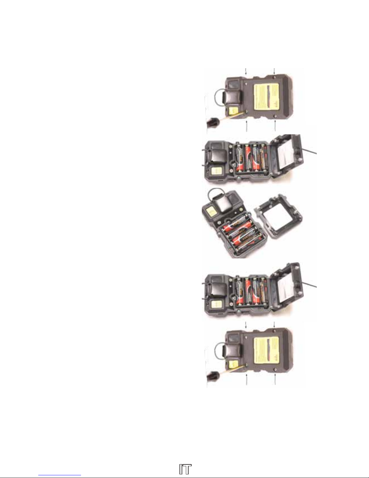
Operation - Battery Installation - Alkaline Batteries
Caution: Always change batteries in an environment free of combustible gas.
Follow your local regulations for proper disposal of alkaline batteries.
1. The battery compartment is located
on the bottom of the back side of the
housing. Loosen the four #0 Phillips type
screws recessed at the top outer edges
of the battery compartment cover.
2. Remove the battery compartment cover
by pulling it away from the main body
of the instrument at the top of the
battery housing. This will release the
bottom hinge locks for cover removal.
3. Remove and install four new approved
alkaline “AA” type batteries. Note the
polarity. If the batteries are installed
incorrectly no damage to the instrument
will occur though it will not operate.
4. Insert the bottom of the battery
compartment cover into the housing and
rotate the cover into position.
5. Tighten the four retaining screws.
Do not over tighten.
1.888.475.5235
info@Sensit-Direct.com
SENSIT-Direct.com
13
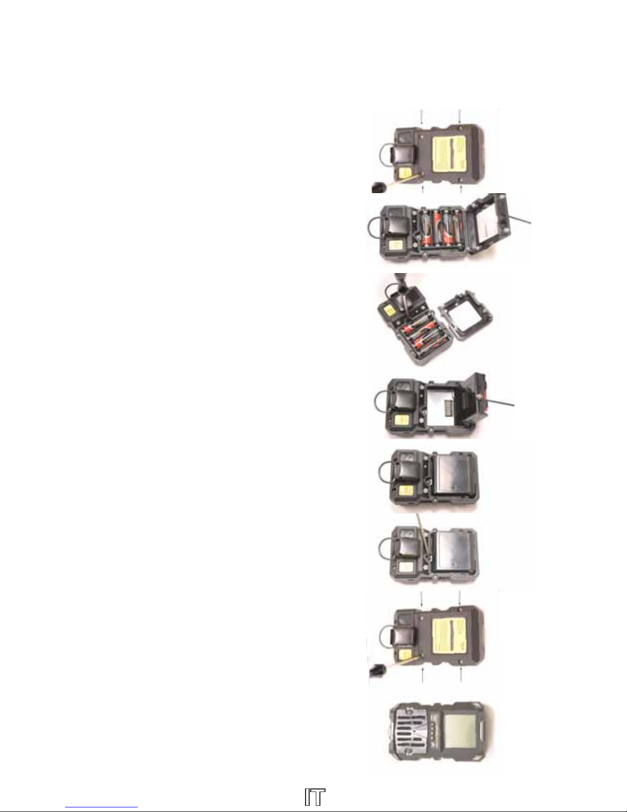
Operation - Battery Installation - Rechargeable Pack
Caution: Always change batteries in an environment free of combustible gas.
Use only Sensit Technologies approved battery pack. Follow your local regulations
for proper disposal of the rechargeable battery pack.
1. The battery compartment is located on the
bottom of the back side of the housing Loosen
the four #0 Phillips type screws recessed at the
top outer edges of the battery compartment
cover.
2. Remove the battery compartment cover by
pulling it away from the main body of the
instrument at the top of the battery housing. This
will release the bottom hinge locks for cover
removal.
3. Loosen the #0 Phillips screw retaining at the
base of the alkaline or rechargeable pack.
4. Gently remove the pack by pulling upward and
allowing the battery pack retaining tabs to slide
out of the holder.
5. Insert the retaining tabs of the battery pack into
position and push gently into position.
6. Replace and secure the retaining screw. Do
not over tighten.
7. Insert the bottom of the battery compartment
cover into the housing and rotate the cover
into position.
8. Tighten the four retaining screws. Do not over
tighten.
9. Recharging is accomplished through the use
of approved battery charger. Charging pins
are located on the front housing of the P400.
1.888.475.5235
info@Sensit-Direct.com
SENSIT-Direct.com

14
Operation – Instrument Charging
Caution: Do not attempt to recharge alkaline batteries.
Use only Sensit Technologies battery pack and charger.
1. Connect battery charger to proper electrical source
(100vac – 240vac) using supplied wall adapter.
Do Not Substitute
a. The green LED will illuminate
2. Lay the P400 face down into the charger cradle.
a. Green LED on and ashing Red LED
indicate charging in progress
b. Green and Red LED constantly on
indicate full charge
c. Green and Red LED ashing indicate a
charging error. Disconnect and retry.
Operation – Button use from working display
1. Power ON
Press upper right button (O) until the display
illuminates to power on.
2. Power OFF
Press and hold upper right (O) + upper left
(r) buttons for 6 seconds at the same time to
power off.
3. Access User Menu
Press and hold lower right (X) + lower left (s)
buttons for 3 seconds to access the user menu
4. Save Current Data (Snapshot)
Press and hold any button for 2 seconds to
save current data (snapshot)
5. Activate Backlight
Press and release any button to activate the
backlight for the preset time (30 seconds
default).
6. Reset IDS
Press and release any button to reset IDS
indicator (if activated).
O
X
r
s
1.888.475.5235
info@Sensit-Direct.com
SENSIT-Direct.com

15
Operation – Button Use From Menu
1. Press and hold lower right (X) + lower left (s) buttons for 3 seconds to access the
user menu.
2. Press either the upper or lower left button to scroll through the selections.
3. Press the upper right button to select a menu item.
4. Press the lower right button to return to the working display.
Menu items include:
a. Set Time – change clock time (24hr basis)
b. Set Date – change date. ddMONyyyy format
c. Auto Zero – perform a re-zero of all sensors.
d. Auto Cal – Calibrate all sensors
e. Peak Hold – Show Peak readings on display (102 Maximum Entries)
f. Bump Test – Perform sensor/alarm function test
g. Bump Log – displays last 93 bump tests for each sensor
including date/time (93 Maximum Entries)
h. Cal Log – displays last 10 gas calibrations for each
sensor including date/time. (10 Maximum Entries)
i. Data Log – View contents of automatic data log. (10752 Maximum Entries)
j. Snapshots – View instant saves (100) which includes all readings
and date/time (102 Maximum Entries)
k. Event Log – displays all alarm events including date/time (120 Maximum Entries)
l. Settings – Display operational info such as alarm settings
m. Supervisor – Supervisor adjustable features (password protected)
1.888.475.5235
info@Sensit-Direct.com
SENSIT-Direct.com

16
Operation - Start Up
Caution: Always start instruments in an area known to be of normal oxygen
content and to be free of combustible gases and contaminants.
1. Push and hold the upper right button (O) until the instrument activates.
2. The instrument will perform a set of self tests. During this time the display will
show:
a. System Check
i. Name of company/user (optional)
ii. Serial number
iii. Battery check
iv. Calibration gas type
v. Software version number
vi. Time
vii. Date
b. UI Check – User Interface check (alarm activations)
i. Top Red LED
ii. Bottom Red LED
iii. Top Green LED
iv. Sounder
v. Vibration
1. Each alarm activation test is indicated
by reverse display highlight and remains
on for 3 seconds
c. Warm Up
i. Display “Please wait” for a minimum of 10 seconds.
ii. If a power supply failure occurs, the instrument will display
“SERVICE REQD” followed by a listing of the type of failure.
VIB VOLT: FAIL indicating a voltage failure to the vibratory motor
BIAS VOLT: FAIL indicating a voltage failure to the electrochemical sensors
EX VOLT: FAIL indicating a failure to the combustible gas sensor
A countdown timer will show the amount of time
remaining before the instrument turns off.
Pressing the two top buttons will also power the
instrument off immediately.
Consult Sensit Technologies for further assistance.
1.888.475.5235
info@Sensit-Direct.com
SENSIT-Direct.com

17
Operation - Start up (Continued)
d. Auto Zero – indicating automatic zeroing process (clean air only)
i. Displays sensor type and PASS or FAIL
ii. If a sensor indicates FAIL the information
will be in reverse contrast.
1. Press any button to acknowledge
and continue warm up
e. Calibration due dates (when scheduled calibration is due next)
i. Displays sensor type and number of days remaining
ii. If a sensor is past due the displayed information will be in reverse
contrast
iii. Press any button to acknowledge calibration past due (if activated).
1. Use left side buttons to highlight SKIP or CALIBRATE
a. SKIP allows operation. Info will be recorded
b. CALIBRATE allows for immediate manual or automated
calibration.
f. Optional Bump Test
i. Display will prompt user to perform bump test if activated as part
of the supervisor set up.
ii. Onscreen selection allows SKIP or BUMP.
iii. Bump test is updated automatically for next required test upon
successful completion.
g. Sensit Logo will be displayed
h. Working display
3. All readings show horizontally “gas type” “concentration”
“unit of measure” and IDS status (if enabled).
4. The instrument is now reading gases as ltered through the ambient dust lter on
the front of the instrument.
a. To check lter remove two 3/32 Allen screws from the front of the
instrument. Check and/or clean lter prior to each days use with
warm water only. For Filter Replacement, see page 22.
5. A green ickering LED indicates the instrument has been bump tested and
calibrated per company regulations and is operating normally.
Caution:
Always check the lter membrane for damage
or excessive dirt or dust which will prevent gas
samples from being sensed.
1.888.475.5235
info@Sensit-Direct.com
SENSIT-Direct.com

18
Operation - Field Use
1. After successful start up, test the work area based on State, Federal,
Municipal or Company work procedures.
2. To test conned spaces
a. The entire instrument can be lowered with a tether by attaching to
the ring on the suspender clip on the back of the instrument. When
tethering, it is best to operate the instrument using the “Peak Hold”
function. Use Menu Function to enable.
b. Use a probe with the aspirator assembly. See page 27 for details.
c. Use the Motorized sample system. See page 27 for details.
3. For instruments with the optional auxiliary
pump attached, connect the probe assembly.
Test each level you wish to check for 90
seconds to make sure the work area is safe.
4. During use in the work area, the suspender
clip will secure the instrument to a belt or
clothing. A “D” ring is part of the clip if you
wish to hang the instrument near the area
where personnel are performing work.
5. To view the display in a darkened
environment, push and release any button.
The backlight will remain on for 30 seconds.
6. The Immediate Detection System (IDS)
will begin to tick when the preset value is
exceeded. The tick will incrementally increase with each increased change
in concentration. Push any button to reset.
7. During alarms conditions the backlight will illuminate, the LED’s will ash,
the vibrator will activate and the alarm sound will be heard. Only during
LOW alarms when TWA alarms are activated can the sound be muted and
the vibrator deactivated by pressing any button (Using snooze feature in
supervisor menu-default is off so no mute is possible). The LED’s will continue
to ash during the mute phase.
1.888.475.5235
info@Sensit-Direct.com
SENSIT-Direct.com

Operation - Field Use (Continued)
8. During STEL alarms no muting or deactivating is
possible.
9. During HIGH or HIGH HIGH alarms no muting
or deactivating is possible.
10. Any gas that is in the alarm mode, the alarm
type will be displayed in reverse dark contrast.
If the IDS feature is activated, it will be reversed
in gray contrast.
11. The LEL sensor has a maximum reading of
110%. This reading will latch if the oxygen
level also drops below 15% while in this over-
range reading.
12. Latching alarms, if the feature is activated,
require the push of a button to disable any alarm only if the gas concentration
has reduced at a non-alarm level.
13. When the shift time feature is enabled and the end of shift alarm activates
press the button corresponding to Yes or No for continuing shift. Each
acknowledgement adds one additional hour.
14. Snapshot is performed by pressing any button for 2-3 seconds. This will store all
onscreen readings for upload or review. The screen will ash momentarily.
15. Battery low indication will activate when the battery voltage reaches 4.1v. At
4.0v the instrument will turn off.
16. If the automatic power off alert activates press any button to add one additional
hour of runtime.
19
1.888.475.5235
info@Sensit-Direct.com
SENSIT-Direct.com

20
Alarms
Caution: During any alarm follow company procedures!
The Sensit P400 has a wide range of alarm types that can be activated through
the User Set Up menu. The alarm types range from those with a simple set point
to those using TWA and STEL measurements required by those customers with
more sophisticated users or operational standards as implemented by an industrial
hygienist.
Each alarm will cause a unique display message and alarm cycle to be heard based
on the level or severity of the gas mixture present. During any alarm the working
display will highlight the particular gas, the concentration and the backlight will be
turned on. Other alarm indications will include:
• Low Alarm/TWA alarm = Display in reverse contrast; Display alarm type
“Low” or “TWA”; Top and bottom LED’s will ash and vibrating motor will
operate for 1 second intervals; alarm sound will be heard; all alarms will
repeat every 2 seconds; muting will cause the contrast to become grey in color.
• High alarm = Display in reverse contrast; Display alarm type “Hi”; Top and
bottom LED’s will ash 1/2 of a second intervals; alarm sound will be heard
every 1/2 of a second interval; the vibrating motor will operate every 1/2 of a
second intervals; for all alarms will repeat every 2 seconds; no muting is possible.
• HiHi/STEL alarm = Display in reverse contrast; Display alarm type “HiHi” or
“STEL”; Top and bottom LED’s will ash 2/10ths of a second intervals; alarm
sound will be heard every 1/10th of a second interval; the vibrating motor will
operate every 1/2 of a second intervals; for all alarms will repeat every 2
seconds; no muting is possible.
1.888.475.5235
info@Sensit-Direct.com
SENSIT-Direct.com
Table of contents
Other Sensit Measuring Instrument manuals

Sensit
Sensit GOLD 100 User manual

Sensit
Sensit HCN User manual

Sensit
Sensit CO User manual

Sensit
Sensit ULTRA-TRAC APL Programming manual

Sensit
Sensit CO User manual

Sensit
Sensit HCN User manual

Sensit
Sensit GOLD G2 User manual

Sensit
Sensit HXG-3 Programming manual

Sensit
Sensit P100 User manual

Sensit
Sensit PTS350A User manual


