envea ProSens User manual

OPERATING INSTRUCTIONS
ProSens (Ex)
ONLINE DUST MEASUREMENT
ENVEA Process GmbH - Gutedelstraße 31 – 79418 Schliengen - GERMANY
Tel.: +49 (0) 7635 827248-0 / info.process@envea.global / www.envea.global
certied
according
to ATEX

The display is touch-sensitive. Available keys are displayed directly in context. When the measuring
system is rst started, a query is initiated to select the language and sensor.
Initialization screen when the Evaluation unit in the eld housing
started rst time.
Selection of the menu language: Deutsch, English, Français.
If a language has been selected, the sensor to be used must be
selected. To be available:
SolidFlow 2.0, Paddy, PicoFlow, MaxxFlow HTC, DensFlow,
SpeedFlow 2.0, SlideControl 2.0, ProSens, M-Sens 2, M-Sens 3,
M-Sens WR, M-Sens WR2.
If any data has been changed, the change will only be taken
into account when you exit the complete menu structure and
answer [Yes] when asked if you wish to save the changes.
Afterwards the start page appears.
If you want to communicate with our sensor using our dedicated software, you need to download the
latest version on our website and install it.
https://www.envea.global/solutions/process-optimization/dahs-software/
It might also be necessary to install drivers, also available on our website.
1st start note
For the 1st use of the sensor, correct sensor type should be selected via the screen or the software.
Software must be installed if needed.
1. SOFTWARE INSTALLATION
2. MSE 300-FH (WITH SCREEN)
Select Language
D E F
E
#
$
8
Sensor
SolidFlow
Save changings?
J N

1st start note
Our dedicated software must be used to connect to the sensor Evaluation unit.
Select software language
Right click on „Sprache/Language/
Langue“ and select desired language.
Connect to sensor
Select the correct COM port and
connect to the device using the „read
device“ button.
Select correct sensor
In the menu „System“, under „Sensor“
(8.2.5 or 7.2.5), the correct sensor must
be selected.
After selecting the sensor, check the
box „Overwrite measurement calib.“
and conrm with the button „Device
program“.
For more informations and details, ple-
ase refer to the user manual of the sen-
sor.
3. MSE 300-DR / -DR2 (NO SCREEN)

2
CONTENTS Page
1. Introduction. . . . . . . . . . . . . . . . . . . . . . . . . . . . . . . . . . . . . . . . . . . . . . . 3
1.1 Safety . . . . . . . . . . . . . . . . . . . . . . . . . . . . . . . . . . . . . . . . . . . . . . . . 3
1.2 Product overview . . . . . . . . . . . . . . . . . . . . . . . . . . . . . . . . . . . . . . . . . 3
1.3 Reliability . . . . . . . . . . . . . . . . . . . . . . . . . . . . . . . . . . . . . . . . . . . . . . 3
1.4 How the device works . . . . . . . . . . . . . . . . . . . . . . . . . . . . . . . . . . . . . . 3
2. Installation. . . . . . . . . . . . . . . . . . . . . . . . . . . . . . . . . . . . . . . . . . . . . . . . 4
2.1 Determining the installation site . . . . . . . . . . . . . . . . . . . . . . . . . . . . . . . . . 4
2.2 Sensor installation - Standard . . . . . . . . . . . . . . . . . . . . . . . . . . . . . . . . . 6
2.3 Sensor installation - High temperature socket . . . . . . . . . . . . . . . . . . . . . . . . 6
2.4 Sensor installation - mounting with TriClamp . . . . . . . . . . . . . . . . . . . . . . . . 7
3. Safety . . . . . . . . . . . . . . . . . . . . . . . . . . . . . . . . . . . . . . . . . . . . . . . . . . 8
3.1 Normal use . . . . . . . . . . . . . . . . . . . . . . . . . . . . . . . . . . . . . . . . . . . . . 8
3.2 Identication of hazards . . . . . . . . . . . . . . . . . . . . . . . . . . . . . . . . . . . . . 8
3.3 Occupational and operational safety. . . . . . . . . . . . . . . . . . . . . . . . . . . . . . 8
3.4 Maintenance . . . . . . . . . . . . . . . . . . . . . . . . . . . . . . . . . . . . . . . . . . . . 9
3.5 Technical statement . . . . . . . . . . . . . . . . . . . . . . . . . . . . . . . . . . . . . . . 9
3.6 Reliability. . . . . . . . . . . . . . . . . . . . . . . . . . . . . . . . . . . . . . . . . . . . . . 9
3.7 Storage conditions . . . . . . . . . . . . . . . . . . . . . . . . . . . . . . . . . . . . . . . . 9
4. Electrical connection . . . . . . . . . . . . . . . . . . . . . . . . . . . . . . . . . . . . . . . . 10
4.1 Sensor connection. . . . . . . . . . . . . . . . . . . . . . . . . . . . . . . . . . . . . . . . . 10
4.2 Evaluation unit MSE 300. . . . . . . . . . . . . . . . . . . . . . . . . . . . . . . . . . . . . 11
4.3 DIN Rail Evaluation unit . . . . . . . . . . . . . . . . . . . . . . . . . . . . . . . . . . . . . 12
4.4 Connecting multiple sensors using the C3-Box . . . . . . . . . . . . . . . . . . . . . . . 13
4.5 Use in Ex hazardous areas . . . . . . . . . . . . . . . . . . . . . . . . . . . . . . . . . . . 14
4.6 Related standards . . . . . . . . . . . . . . . . . . . . . . . . . . . . . . . . . . . . . . . . 15
4.7 Um. . . . . . . . . . . . . . . . . . . . . . . . . . . . . . . . . . . . . . . . . . . . . . . . . 15
5. Dimensions . . . . . . . . . . . . . . . . . . . . . . . . . . . . . . . . . . . . . . . . . . . . . . . 16
5.1 Sensor . . . . . . . . . . . . . . . . . . . . . . . . . . . . . . . . . . . . . . . . . . . . . . . . 16
5.2 Field housing Evaluation unit . . . . . . . . . . . . . . . . . . . . . . . . . . . . . . . . . . 16
5.3 DIN Rail Evaluation unit . . . . . . . . . . . . . . . . . . . . . . . . . . . . . . . . . . . . . 17
5.4 C1 Box dimensions (optional) . . . . . . . . . . . . . . . . . . . . . . . . . . . . . . . . . . 17
5.5 C3 Box dimensions (optional). . . . . . . . . . . . . . . . . . . . . . . . . . . . . . . . . . 18
6. Operation . . . . . . . . . . . . . . . . . . . . . . . . . . . . . . . . . . . . . . . . . . . . . . . . 18
6.1 Basic operation of the touchscreen (only eld housing). . . . . . . . . . . . . . . . . . . 18
6.2 Basic information on the user interface . . . . . . . . . . . . . . . . . . . . . . . . . . . . 19
6.3 Differences between the DIN Rail and eld housing Evaluation unit . . . . . . . . . . . 19
6.4 Display . . . . . . . . . . . . . . . . . . . . . . . . . . . . . . . . . . . . . . . . . . . . . . . 20
6.5 PC interface . . . . . . . . . . . . . . . . . . . . . . . . . . . . . . . . . . . . . . . . . . . . 22
6.6 Menu structure . . . . . . . . . . . . . . . . . . . . . . . . . . . . . . . . . . . . . . . . . . 25
7. Fitting up to 3 sensors. . . . . . . . . . . . . . . . . . . . . . . . . . . . . . . . . . . . . . . . .34
8. Maintenance . . . . . . . . . . . . . . . . . . . . . . . . . . . . . . . . . . . . . . . . . . . . . . 35
9. Warranty . . . . . . . . . . . . . . . . . . . . . . . . . . . . . . . . . . . . . . . . . . . . . . . . 35
10. Error message / Sensor status . . . . . . . . . . . . . . . . . . . . . . . . . . . . . . . . . . . .35
10.1 Response to errors . . . . . . . . . . . . . . . . . . . . . . . . . . . . . . . . . . . . . . . . 35
11. Technical data . . . . . . . . . . . . . . . . . . . . . . . . . . . . . . . . . . . . . . . . . . . . . 36

3
1. Introduction
1.1 Safety
The ProSens dust sensor requires a 24 ±10 % V DC supply. 24 ±10 % V DC is regarded as safe.
The DIN Rail converter requires a 24 ±10 % V DC supply. 24 ±10 % V DC is regarded as safe.
Precautionary measures:
The pipe must be opened for installation and maintenance.
The following risks must be borne in mind:
• Harmful escape by gas or dust.
• Escaping material may be inammable, explosive or toxic.
• Escaping material may be hot or pressurised.
1.2 Product overview
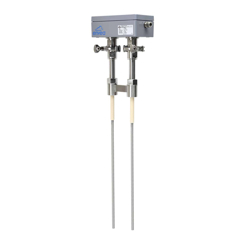
The ProSens dust sensor is a microprocessor-based, preset device for measuring dust concentrations
in a moving air stream. The ProSens serves for monitoring the pure side after lter elements and for
the quantitative measurement of dust concentrations in exhaust air ducts.
The ProSens is a compact device for simple installation and functioning. The sensor electronics are
accommodated in an IP 66 housing. The Evaluation unit is accommodated in a maintenance housing
with touchscreen as standard.
A DIN Rail converter is also available, which is congured via a PC. The PC conguration can be
carried out at the Field housing via USB or RS 485 interface.
USB or RS 485 communication is possible for the DIN Rail evaluation.
PC software, which can also be used to change internal parameters of the sensor (lter times, alarm
retention times etc.), is optionally available. This software also allows parameter les and log les
from the measuring value logging to be saved, with an additional option for trend visualisation.
The ProSens is designed for use in applications of up to 2 bar pressure and 500 °C.
The system can optionally be installed in explosive zones of category 1/2 gas + dust.
The sensor is connected to a 4-wire cable, via which the supply and digital communication is routed
to the Evaluation unit.
1.3 Reliability
For any additional information concerning product reliability, please contact ENVEA Process.
1.4 How the device works
The ProSens dust measuring instrument is based on the electrodynamic technology: Dust particles
streaming past or impinging on the probe exchange the smallest electrical charges with the probe.
These small electrical charges lead to a signal, which is proportional to the dust load in the air owing
past, even if particles accumulate on the probe.
A reliable measuring value can consequently be attained with this almost maintenance-free and non-
wearing measuring system.

4
The device is ready for operation immediately after switching on with default settings and is
congured and calibrated either with the Evaluation unit MSE 300 or with the conguration software.
The use of a PC is required for commissioning measuring units with DIN Rail evaluation. Freely
denable alarm thresholds for a minimum or maximum alarm are available within the measuring range.
If the relay contact “normally closed” (NC) is used, the sensor is automatically tested for power failure.
The internal error message from the sensor also signals any faults occurring via the relay.
The Evaluation unit provide a 4 ... 20 mA power output as a measuring value output or or as trend
display for the dust load.
If a fault is found during the internal function test, the power output is set to 2 mA.
2. Installation
2.1 Determining the installation site
The best installation position for the sensor in a duct or a pipe is located in an area, in which the
particles undergo a uniform distribution and ow past the sensor at a uniform velocity.
The installation site can be in a horizontal or vertical pipe.
In the best case, the duct or pipe continues upstream and downstream of the installation site
horizontally or vertically and ttings or manifolds, valves or slides have a minimum distance to the
sensor in both directions. (See Fig. 2)
Fig. 1
3 x DN 3 x DN
3 x DN 3 x DN
3 x DN
3 x DN
3 x DN
3 x DN
Fig. 2: Recommended distances to valve, etc. (DN = nominal diameter)

5
The best possible installation location should be chosen in applications that cannot fully satisfy the
requirements for the installation location.
The dust sensor must be installed in a metallic duct in order to attain sufcient shielding against
electrical inuences.
In case of non-metallic lines, a metal casing, a metal foil or a ne-meshed metal net with a length of
approx. 5 times the pipe diameter must be provided upstream and downstream of the measuring point.
It must also be ensured that the duct and sensor are earthed properly.
1. The ProSens should be installed so that the dust impinges on the sensor rod at an angle of 90°.
2. In horizontal pipes with a round cross-section, the ProSens can be installed in any position above the
horizontal axis (between 9 and 3 o’clock). (See gure 3a)
3. In horizontal pipes with a square cross-section, the installation can be in the centre at the top or side.
(See gure 3b)
4. Even though the sensor function is not impaired by vibration, strong vibrations should be avoided, as
they can lead to destruction of the electronics.
5. The sensor should not be exposed to direct sunlight, or used in area with an ambient temperature of
more than 60 °C.
6. The sensor rod must not come into contact with the opposite pipe wall or any other device!
The electrodynamic signal would be short-circuited by this. The length of the sensor can be
shortened to a minimum length of 70 mm for this. The plastic sleeve must not on any account be
damaged here.
• The length of the sensor rod should be minimum 1/3 and maximum 2/3 of the duct diameter.
However, it must always be ensured that contact through bridge formation does not result,
even if deposits form on the inside wall of the pipe.
• A golden rule: the lower the dust concentration, the longer the rod length.
7. A position downstream of the blower is generally recommended as an installation position for
monitoring a lter system. If the sensor is used downstream of an electric lter, the distance to the
electric lter should be minimum 20 metres. Even though the sensor function is not impaired by
vibrations, very high vibrations over a longer time period should be avoided.
Fig. 3a: Round cross-section
▼
▼
ProSens in the
horizontal axis.

6
Fig. 3b: Square cross-section
2.2 Sensor installation - Standard
The R 1” internal threaded socket is rst welded onto the pipe wall in the chosen installation location
and fully drilled to the inside diameter of the socket. The sensor is then screwed in tightly.
Check the connection for tightness.
Important:
•Use the correct tool (wrench size = S37) and place it on the G 1" screw connection.
Do not screw the sensor in by hand since the screw connector could come loose and this can
damage the electronics.
•Incorrect installation will void the warranty!
2.3 Sensor installation - High temperature socket
1Weld the main socket (A) onto the pipe in the chosen installation location and fully drilled to the
inside diameter of the socket.
2Carefully insert the ceramic cartridge (B) into the socket.
3 Position the ange (C) and mount it with the 4 bolts (D). Use the proper tool (Wrench size 27).
4 Install the G 1 ½” – 1” adapter (E). Use the proper tool.
5Install the ProSens sensor into the assembled socket fallowing instruction in 2.1.
ProSens in the
centre
on the pipe or side.
Fig. 3c: Square cross-section

7
Fig. 3d: Mounting Operations
2.4 Sensor installation - mounting with TriClamp
Weld the ange “A” on the duct wall and opened by drill completely. (Ø 20 mm)
Mount the sensor “E” on female socket “C” using the proper wrench.
Caution:
•Use the correct size wrench. Do not screw the sensor in by hand since the screw connector
could come loose and this can damage the electronics.
•Do not undo the grub screw in the housing plinth.
Lock female socket “C” on welded socket “A” using the clamp collar “D”.
Do not forgot the clamp gasket “B”
1
2
3
Fig. 3e: Assembled TriClamp

8
3. Safety
The sensor was designed, built and tested for safety and is shipped in this condition. Components within
the supplied system could be hazardous if not unpacked, installed, connected and commissioned by
authorised qualied persons. All operating instructions must be read, and understood, before handling the
system. Failure to do so will cause the warranty to be revoked.
3.1 Normal use
•The measuring system may only be installed for measuring the low ow rate in metallic pipes.
•Only original spare parts and accessories of ENVEA Process GmbH must be used.
3.2 Identicationofhazards
Possible hazards, when using the measuring system, are marked by the following symbols:
Warning!
•This symbolises a situation where personal safety is at risk if used in an improper manner.
Attention!
•This symbolises the possible damage to the system, if used in an improper manner.
3.3 Occupational and operational safety
•The measuring system must be installed by trained and authorised personnel only.
•Protective equipment must be worn to avoid injuries caused by possible sharp edges on the
measuring device.
•When using a cable with more than 4 cores, unused, open cores may cause sparking. Failure
to comply with the specied connection parameters of the cable will result in loss of intrinsic
safety. To prevent this, it is mandatory to use a 4-core shielded cable.
Always ensure that the connection parameters of the cable are within the specication (Li, Ci).
The shield of the cable must not be connected to the housing under any circumstances.
•When installed in an Ex zone, there is an increased risk of explosion, so it should always be
ensured that there is no Ex zone when carrying out installation work.
•Improper installation work leads to an increased risk of explosion. The device must always be
installed using the process-related seals and observing the torques. Mechanical stresses are to
be avoided, for example through supported installation.
•In case of improper assembly, there is an increased risk of explosion due to escaping dusts.
•Improper mechanical stress (e.g. torsion) can cause damage to the device. To avoid this, the
device should always be installed in accordance with all the instructions in the operating manual.
The measuring device should also not be exposed to any vibrations if possible.
•If the device is operated under high pressured conditions, there is a risk of explosion. When
cleaning or blowing out the pipe and when transporting material, always ensure that the
permissible pressure according to the DGRL is not exceeded.

9
•Due to the process, hot components on the device can cause burns. It is strongly recommended to
wear the appropriate protective equipment and to let the device cool down before working on it.
•Improper use of the device will result in a high risk to system safety, therefore the device must
only be used as specied in the associated documentation.
•Make sure that the system is in a depressurised state during all maintenance, cleaning and
inspection work on the pipelines or on the components of the device.
•In case of maintenance-work on the pipe or on components of the sensor, make sure that the
piping is in unpressurized condition.
•Switch off the power supply for all maintenance, cleaning or inspection works on the sensor or
on components. Follow the notes of the chapter maintenance.
•Caution, if welding is required on the pipe, remove sensor.
•The components and electrical connections must be checked for damages regularly. If a damage
is found, it is to be repaired before further operation of the instruments.
3.4 Maintenance
•For maintenance purposes, it is imperative that the device is de-energised and cooled down,
otherwise there is an increased risk of explosion.
•Before working on the device or its components, it is essential to ensure that they are de-
energised. Otherwise there is a risk of electric shock.
•The correct tool must be used to open the device, otherwise there is a risk of injury and
crushing.
•Before opening the device or its components, it is imperative to ensure that there is no EX zone.
•During cleaning work on the device or in the process, there is an increased risk of explosion due
to electrostatic discharges and excessive pressures.
3.5 Technical statement
The manufacturer reserves the right to change any technical data concerning technical
developments, without prior notice. If any queries arise, ENVEA Process GmbH will be happy to
inform customers of any possible changes made.
3.6 Reliability
For any additional information concerning product reliability, please contact ENVEA Process GmbH.
3.7 Storage conditions
Observe the following instructions during storage:
•To ensure shock resistance, store in original packaging.
•Do not remove protective discs or caps mounted on process connections.
They prevent mechanical damage and contamination to the sealing surfaces.
•Protect from sunlight to avoid impermissibly high surface temperatures.
•Store in a dry and dust-free place.
•Do not store outside.

10
4. Electrical connection
The ProSens has an internal connection chamber with plug-in contacts which can be cabled to suit
the appropriate installation options.
Note: For EX versions cat. 1 and 2, the relay contact is only available at the Evaluation unit and not at
the sensor.
4.1 Sensor connection
Field housing connection
Sensor PME
Max. 300 m using
wire of appropriate
cross sectional area
1
2
3
4
1(+ 24 V)
2 (GND)
3 (A)
4 (B)
Shield
A shielded, stranded cable is recommended for long distances and environments with major
interference sources!
Sensor DIN Rail Converter
Up to 300 m
at sufficient wire
cross section
16 (+ 24 V)
15 (GND)
14 (A)
13 (B)
1
2
3
4
DIN Rail connection
Fig. 4: Electrical connection
Tab. 1: Sensor connection
Fig. 6: DIN Rail connection
Fig. 5: Field housing connection
+24 V
0 V
RS 485 - A
RS 485 - B
NO
COM
NC
Contact no. Signal
1 V+ (24 V DC)
2 V- (0 V)
3 RS 485 - A
4 RS 485 - B
5 No function
6 No function
7 No function

11
4.2 Field housing MSE 300 Evaluation unit
Fig. 7: Electrical connection
Evaluation unit
Terminal no. Connection
Power supply connection
L / +24 V Input power supply 230 V / 50 Hz, 110 V / 60 Hz (optional 24 V DC)
N / 0 V Input power supply 230 V / 50 Hz, 110 V / 60 Hz (optional 24 V DC)
PE Earth
Connections
I-in 1 +Current input +
-Current input -
I-out 1 +Current output +
-Current output -
I-out 2 Na Not used
Na Not used
I-out 3 Na Not used
Na Not used
Relay
NO Floating change-over contact NO (make contact)
CFloating change-over contact COM (common conductor)
NC Floating change-over contact NC (break contact)
D-out 1 Na Not used
Na Not used
RS 485
ARS 485 interface data A (+)
BRS 485 interface data B (-)
GND RS 485 interface ground
D-in 1 Na Not used
Na Not used
D-in 2 Na Not used
Na Not used
Sensor
+Power supply 24 V (+) Cable no. 1
-Power supply 24 V (-) Cable no. 2
ARS 485 data A Cable no. 3
BRS 485 data B Cable no. 4
Shield Shield Shield
Tab. 2: Field housing connections
L N PE
I-in 1 I-out 1
+ -
I-out 2 I-out 3
Alarm Relay
NO C NC
D-out RS 485
A B
GND
D-in 1 D-in 2 Sensor
+ - A B
Shield
+ - + - + - + -
+ -
+ -

12
4.3 DIN Rail MSE 300 Evaluation unit
Current output
- 4 ... 20 mA
Current output
+ 4 ... 20 mA
Input
power supply
0 V DC
Input
power supply
+ 24 V DC
Not used Alarm relay
NC (break contact)
Alarm relay
COM
Alarm relay
NO (make contact)
1 2 3 4
5 6 7 8
Digital
pulse output (-)
Digital
pulse output (+)
RS 485-
Interface
Data B
RS 485-
Interface
Data A
Sensor connection
Cable 4
RS 485
Data B
Sensor connection
Cable 3
RS 485
Data A
Sensor connection
Cable 2
power supply 0 V
Sensor connection
Cable 1
power supply + 24 V
9 10 11 12
13 14 15 16
Fig. 8: DIN Rail connections

13
4.4 Connecting multiple sensors using the C3-Box
As an option up to 3 sensors can be connected to the Evaluation unit via the C3-Box to allow large
pipe cross-sections to be monitored with accuracy.
TransmitterC3-Box
Sensor
Sensor
Sensor
2 m max. 300 m
1 (+ 24 V)
2 (GND)
3 (A)
4 (B)
Shield

14
4.5 UseinExhazardousareas
The electronics of the sensor are designed to be intrinsically safe with respect to the rod probe. The sepa-
ration between the intrinsically safe circuit at the rod probe and other parts of the electronics, protected by
ameproof enclosure for explosive gas atmospheres and by enclosure for explosive dust atmospheres, takes
place within the housing.
With this setup, cabling with intrinsically safe circuits, blue sheathed cables, and blue ttings are not required.
Marking DustEx: II 1/2D Ex ia/tb IIIC Tx* Da/Db
Zone 20: -20 °C _< Tprocess _< 240 °C
Zone 21: -15 °C _< Tamb _< 60 °C
The electronic enclosure of PicoFlow Ex 62-0004 may not be installed in dust Ex-areas where intensive
charging processes are to be expected.
- Equipment group: 2
- Equipment category: 1/2 Electrode zone 20 / enclosure zone 21
- For explosive mixtures of air and combustible dusts
- IP-code 68
- Permitted process temperature -20 to 240 °C
- *
Up to process temperatures of 120 °C, the maximum surface temperature of the electronic
enclosure is 120 °C. In case of higher process temperatures. At higher process temperatures the
allowable surface temperature is determined by the process temperature.
- The intrinsical electrode circuit is operated grounded. Lightning protection measures
(acc. to IEC/EN 60019-14) for Zone 1 / Zone 20 must be followed by the operator.
Marking GasEx: II 2G Ex db ia IIC T4* Gb
Zone 1: -20 °C _< Tprocess _< 240 °C
Zone 1: -15 °C _< Tamb _< 60 °C
The sensor is not allowed to be used in areas of class IIC, in case of expected, intense charging
processes.
- Equipment group: 2
- Equipment category: 2 Electrode and enclosure zone 1
- For explosive mixtures of air and combustible dusts
- IP-code 68
- Permitted process temperature -20 to 240 °C
- *
Up to process temperatures of 130 °C, the sensor corresponds to temperature class T4.
At process temperatures up to 195 °C, the sensor corresponds to temperature class T3 and at
process temperatures up to 240 °C, the sensor corresponds to temperature class T2.
- The intrinsical electrode circuit is operated grounded. Lightning protection measures
(acc. to IEC/EN 60019-14) for Zone 1/Zone 20 must be followed by the operator.

15
Hazardous Area
DustEx Zone 20
GasEx Zone 0
DustEx Zone 21
GasEx Zone 1
Non-hazardous Area
Tmax = 60 °C
Tmax =
240 °C
4.6 Related standards
ATEX (BVS 13 ATEX E 096 X)
EN IEC 60079-0: 2018
EN 60079-1: 2014
EN 60079-11: 2012
EN 60079-31: 2014
4.7 Um
Um(Supply) = 26.5 V
Um(RS485) = 5.5 V

16
5. Dimensions
5.1 Sensor
Fig. 11: ProSens / ProSens Ex dimensions
5.2 Field housing Evaluation unit
Fig. 12: Field housing for the Evaluation unit
R 1”

17
5.3 DIN Rail Evaluation unit
Fig. 13: DIN Rail dimensions
5.4 C1-Box dimensions (optional)
Fig. 14: C1-Box dimensions
Cable gland
M 20 x 1,5
Sensor 1Transmitter
118
35
23
90

18
Transmitter Sensor 1 Sensor 2 Sensor 3
M20 M20
6. Operation
The ProSens dust measuring instrument measures the dust content in a gas passing the sensor using
the electrodynamic principle by means of the exchange of charge carriers between the dust particles
and the sensor's probe.
After switching on, the ProSens already begins to measure with the default factory settings.
Commissioning can be carried out at the Evaluation unit MSE 300 optionally via the touchscreen or
with the conguration software. Only PC conguration is possible for the DIN Rail version. The menu
structureornumberingisidenticalfortouchscreenandPCconguration,whichmeansthedetailed
description for this applies to both versions in this operating manual. Any deviations from this will
be explained separately.
6.1Basicoperationofthetouchscreen(onlyeldhousing)
To start the conguration menu, the top right half of the touchscreen needs to be pressed for a few
seconds.
The main overview with software version number as well as four operating keys appears on the right
of the screen.
- Up key
- Down key
- C key (e. g. also E key)
- Enter key
Press the Up or Down key to navigate in the menu, or the Enter key to enter a submenu item. To quit
a submenu or the entire conguration menu, press the C key (Cancel), likewise to cancel an entry or
selection. The can also be the E key (Escape), depending on the menu or function.
5.5 C3-Box dimensions (optional)
Fig. 15: C3-Box dimensions
Table of contents
Other envea Measuring Instrument manuals
Popular Measuring Instrument manuals by other brands
KROHNE
KROHNE GFM 700 K Installation and operating instructions

Meditech Europe
Meditech Europe Multiwave Oscillator operating instructions

TechGrow
TechGrow HS-2 manual
Honeywell
Honeywell RM640 Handbook
PCB Piezotronics
PCB Piezotronics 357B69/NC Installation and operating manual

Bosch
Bosch gll3-80 P Original instructions
