Envirolite EVT1042D3-05 User manual

Questions, problems, missing parts? Before returning to the store,
call Envirolite Customer Service
8 a.m. –6 p.m., EST, Monday –Friday
1-855-573-6156
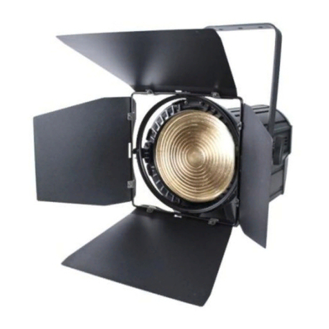
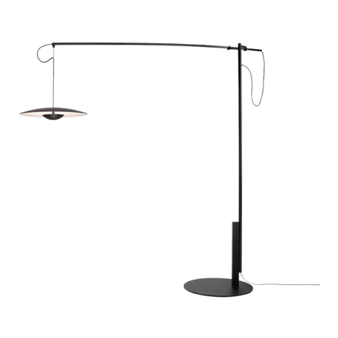
3 HEAD LED TRACK LIGHT
EVT1042D3-05
EVT1042D3-06

SAFETY INFORMATION
Before starting installation of this
fixture or removal of a previous
fixture, disconnect the power by
turning off the circuit breaker or by
removing the fuse at the fuse box.
Consult a qualified electrician if you have any electrical questions or need to
replace the driver.
If you have any non-electrical questions about this fixture, please contact our
Customer Service Team at 1-855-573-6156.
WARNING: Disconnect the
power prior to removing or
installing a light fixture.
PLANNING THE INSTALLATION
NOTE: Keep your receipt and
these instructions for Proof of
Purchase.
This track head required a Hampton Bay brand track bar assembly pre-installed
at the desired installation location. Do not install this track head onto a track made
by any other manufacturer. To avoid damaging this product, assemble it on a soft,
non-abrasive surface such as carpet or cardboard.
TOOLS REQUIRED
2
Safety
Goggles
Electrical
Tape Drill 1/2” Drill
Bit
Ladder Phillips
Screwdriver
Wire
Cutter
Wire
Stripper Pencil

PACKAGE CONTENTS
3
Part
Description
Quatity
A
Track Head
3
B
Track Section
1
C
Canopy
1
D
Mounting Plate
1
E
Canopy Screw
2
F
Mounting Screw
2
G
Wire Nut
3
H
Ceiling Anchor
2
I
Anchor Screw
2
J
Toggle Wing
2
K
Toggle Bolt
2
I
HKJ
DEFG
BC
A

Remove the canopy screws (E)
from the mounting plate (D) to
remove the canopy (C).
Remove the mounting screws (F)
from the mounting plate (D).
Keep all screws and parts.
Connect the black supply wire with
the black wire on the mounting
plate (D) using a wire nut (G).
Connect the white supply wire with
the white wire on the mounting
plate (D) using a wire nut (G).
Connect the supply ground wire
with the ground wire on the
mounting assembly (D) using a
wire nut (G).
Wrap all wire connections with
electrical tape for a more secure
connection.
4
INSTALLATION
D
G
E
F
D
C

Place the track bar (B) onto the
mounting plate (D) over the
desired location.
Mark the locations of the mounting
slots of the track bar (B) with a
pencil. Remove the track bar (B)
from the mounting plate (D).
Drill 1/2” diameter holes at the
marked locations.
Mount the track (B) onto the ceiling
using one of the two methods
below:
1. Use toggle bolts (K) and toggle
wings (J) to mount the track (B)
onto the ceiling. Do not tighten
the toggle bolts (K) at this time
and make sure to leave about
1/2” of space between the
ceiling and the track (B).
2. Insert ceiling anchors (H) into
the ceiling, then mount the
track (B) onto the ceiling using
anchor screws (I). Do not
tighten the anchor screws (I) at
this time and make sure to
leave about 1/2” of space
between the ceiling and the
track (B).
5
INSTALLATION (CONTINUED)
F
B
J
K
I
H

Slip the mounting plate (D) behind
the track (B) and under the outlet
box.
Secure the track (B) to the
mounting plate (D) by screwing the
mounting screws (F) on both sides
of the mounting plate (D).
Secure the canopy (C) onto the
mounting plate (D) with the canopy
screws (E).
6
INSTALLATION (CONTINUED)
B
D
F
B
D
C
E

Select the desired location on track bar for the track head (A).
Identify the grounded side of the track bar by finding the single groove located
on one side of the track channel.
Pull down the spring-loaded outer sleeve on the base of the track head (A).
Insert the track head (A) connector into the track channel and twist the track
head (A) base so that its two contacts turn toward the groove (grounded side)
of the track bar.
Release the outer sleeve, but continue twisting the track head (A) base until
the outer sleeve snaps into the track channel.
7
INSTALLATION (CONTINUED)
B
A

Turn on power at the circuit breaker or fuse box.
Turn the light switch on to activate the fixture.
OPERATION
NOTE: Do not use any cleaners
with chemicals, solvents, or harsh
abrasives. Use only a dry soft
cloth to dust or wipe carefully.
EXTERIOR MAINTENANCE
Use a dry or slightly dampened
clean cloth and wipe the surface
of the fixture.
CARE & CLEANING
8
FCC NOTICE
This device has been tested and found to comply with the limits for a Class B
digital device, pursuant to part 15 of the FCC Rules. These limits are designed to
provide reasonable protection against harmful interference in a residential
installation. This equipment generates, uses and can radiate radio frequency
energy and, if not installed and used in accordance with the instruction manual,
may cause harmful interference to radio communications. However, there is no
guarantee that interference can be determined by turning the equipment off and
on, the user is encouraged to try to correct the interface by one or more of the
following measures:
Reorient or relocate the receiving antenna.
Increase the separation between the device and receiver.
Connect the equipment into an outlet on a circuit different from that to which
the receiver is connected.
Consult the dealer or an experienced radio/TV technician for help.

9
DIMMING
-/+180
150
120
90
60
30
-150
-120
-90
-60
-30
0
500
1000
1500
2000
2500
LIGHT DISTRIBUTION MAP
Problem
Solution
The light will not turn on.
Make sure the power supply is on.
Test or replace the switch.
Check the wiring.
Replace the driver.
The fuse blows or circuit breaker
trips when light is turned on.
Check the wire connections.
TROUBLESHOOTING
For an up-to-date list of compatible dimmers, look up item number at
www.envirolite-LED.com.

WARRANTY
10
WHAT IS COVERED
The manufacturer warrants this lighting fixture to be free from defects in materials
and workmanship for a period of five (5) years from date of purchase. This
warranty applies only to the original consumer purchaser and only to products
used in normal use and service. If this product is found to be defective, the
manufacturer’s only obligation, and your exclusive remedy, is the repair or
replacement of the product at the manufacturer’s discretion, provided that the
product has not been damaged through misuse, abuse, accident, modifications,
alterations, neglect or mishandling.
WHAT IS NOT COVERED
This warranty shall not apply to any product that is found to have been improperly
installed, set-up, or used in any way not in accordance with the instructions
supplied with the product. This warranty shall not apply to a failure of the product
as a result of an accident, misuse, abuse, negligence, alteration, or faulty
installation, or any other failure not relating to faulty material or workmanship.
This warranty shall not apply to the finish on any portion of the product, such as
surface and/or weathering, as this is considered normal wear and tear.
The manufacturer does not warrant and specially disclaims any warranty, whether
expressed or implied, of fitness for a particular purpose, other than the warranty
contained herein. The manufacturer specifically disclaims any liability and shall
not be liable for any consequential or incidental loss or damage, including but not
limited to any labor/expense costs involved in the replacement or repair of said
product.

Preguntas, problemas, o piezas faltantes? Antes de regresar a la tienda,
llama al Servicio al Cliente de Envirolite
8 a.m. –6 p.m., Hora del Este, Lunes –Viernes
1-855-573-6156
EVT1042D3-05
EVT1042D3-06
RIEL FIJO CON 3 CABEZAS LED

INFORMACIÓN DE SEGURIDAD
Antes de iniciar la instalación de
este aparato o la eliminación de
un accesorio anterior, desconecte
la alimentación apagando el
disyuntor o quitando el fusible en
la caja de fusibles.
Consulte a un electricista calificado si tiene alguna pregunta eléctrica o la
necesidad de reemplazar el controlador.
Si usted tiene alguna pregunta que no sea eléctrica sobre este accesorio,
póngase en contacto con nuestro equipo de Servicio al Cliente al
1-855-573-6156.
WARNING: Disconnect the
power prior to removing or
installing a light fixture.
PLANIFICACIÓN DE LA INSTALACIÓN
NOTA: Guarde su recibo y
estas instrucciones para
comprobante de compra.
Lea todas las instrucciones antes del montaje e instalación. Antes de comenzar
la instalación de la luminaria o el retiro de un artefacto anterior, desconecte la
alimentación apagando el disyuntor o quitando el fusible en la caja de fusibles.
Para evitar daños a este producto, montarlo en una superficie suave y no
abrasiva, como una alfombra o cartón.
HERRAMIENTA NECESARIAS
12
Gafas de
Seguridad
Cinta
Aislante Taladro Broca de
1/2”
Escalera Desarmador
de Cruz
Cortador de
Alambre
Pelacab
les Lápiz

CONTENIDO DEL PAQUETE
13
Parte
Descripción
Cantidad
A
Cabeza
3
B
Riel Fijo
1
C
Cubierta
1
D
Placa de Montaje
1
E
Tornillo de la Cubierta
2
F
Tornillo de Montaje
2
G
Tuerca para Cables
3
H
Anclaje de Techo
2
I
Tornillo de Anclaje
2
J
Ala Palanca
2
K
Perno de Anclaje
2
I
HKJ
DEFG
BC
A

Retire los tornillos de la cubierta
(E) de la placa de montaje (D)
para retirar la cubierta (C).
Retire los tornillos de montaje (F)
de la placa de montaje (D).
Mantenga todos los tornillos y
piezas.
Conecte el cable negro de
alimentación con el cable negro de
la placa de montaje (D) utilizando
una tueraca para cables (G).
Conecte el cable blanco de
alimentación con el cable de la
placa de montaje (D) utilizando
una tueraca para cables (G).
Conecte el cable del luminario a
tierra con el cable de alimentación
a tierra de la placa de montaje (D)
utilizando una tueraca para cables
(G).
Envuelva todas las conexiones de
los cables con cinta de aislar para
una conexión más segura.
14
INSTALACIÓN
E
F
D
C
D
G

Coloque la barra en riel (B) en la
placa de montaje (D), sobre el
lugar deseado.
Marque las ubicaciones de los
agujeros de montaje de la barra en
riel (B) con un lápiz. Quite la barra
en riel (B) de la placa de montaje
(D).
Taladre agujeros de 1/2” (1,27 cm)
de diámetro en los lugares
marcados
Monte la pista (B) sobre el techo
usando uno de los dos métodos
siguientes:
1. Use los pernos de anclaje (K) y
las alas palancas (J) para montar
la el riel fijo (B) en el techo. No
apriete los pernos de anclaje (K)
en este momento y asegúrese de
dejar aproximadamente 1/2"
(1,27 cm) de espacio entre el
techo y la pista (B).
2. Inserte los anclajes de techo (H)
en el techo y luego monte el riel
fijo (B) sobre el techo con
tornillos de anclaje (I). No apriete
los tornillos de anclaje (I) en este
momento y asegúrese de dejar
aproximadamente 1/2" (1,27 cm)
de espacio entre el techo y la
pista (B).
15
INSTALACIÓN (CONTINUADO)
F
B
J
K
I
H

Deslice la placa de montaje (D)
detrás del riel fijo (B) y debajo de
la caja de alimentación.
Asegure el riel fijo (B) a la placa de
montaje (D) atornillando los
tornillos de montaje (F) de ambos
lados de la placa de montaje (D).
Asegure la cubierta (C) en la placa
de montaje (D) con los tornillos de
la cubierta (E).
16
INSTALACIÓN (CONTINUADO)
B
D
F
B
D
C
E

Seleccione el lugar deseado en la barra en riel para montar la cabeza (A).
Identifique el extremo a tierra de la barra en riel al encontrar una ranura
ubicada en un lado del canal del riel.
Jale hacia abajo la funda exterior con resorte de la base de la cabeza (A).
Inserte el conector de la cabeza (A) en el canal del riel y gire la base de la
cabeza (A) para que sus dos contactos giren hacia la ranura (extremo a tierra)
de la barra en riel.
Libere la funda exterior, pero continúe girando la base de la cabeza (A) hasta
que la funda exterior entre en el canal del riel.
17
INSTALACIÓN (CONTINUADO)
B
A

Conecte la alimentación en el disyuntor o caja de fusibles.
Gire el interruptor de la luz para activar el aparato.
OPERACIÓN
MANTENIMIENTO DEL EXTERIOR
Use un paño limpio y seco o
ligeramente humedecido y
limpie la superficie de la
luminaria.
CUIDADO Y LIMPIEZA
NOTA: No use limpiadores
con químicos, solventes o
abrasivos fuertes. Use sólo un
paño seco para sacudir o
limpiar con cuidado.
18
AVISO DEL FCC
NOTA: Este aparato ha sido probado y cumple con los límites para un aparato
digital de Clase B, según la Parte 15 de la normativa FCC. Estos límites están
diseñados para proporcionar una protección razonable contra las interferencias
perjudiciales en una instalación residencial. Este aparato genera, utiliza y puede
irradiar energía de radiofrecuencia y, si no se instala y utiliza de acuerdo con las
instrucciones, puede causar interferencias perjudiciales en las comunicaciones
de radio. Sin embargo, no hay garantía de que la interferencia puede
determinarse encendiéndolo y apagándolo, se recomienda al usuario que intente
corregir la interfaz en una o más de las siguientes medidas:
Reorientar o reubicar la antena de recepción.
Aumentar la distancia entre el aparato y el receptor.
Conectar el equipo a un enchufe de un circuito diferente de aquel al que está
conectado el receptor.
Consulte al distribuidor o un técnico de radio/televisión para obtener ayuda.

19
ATENUACIÓN
MAPA DE DISTRIBUCIÓN DE LUZ
Para una lista completa de atenuadores compatibles, por favor a el
numero de articulo que en www.envirolite-LED.com.
SOLUCIÓN DE PROBLEMAS
Problema
Solución
La luz no se enciende.
Asegúrese de que la energía
eléctrica esté encendida.
Pruebe o cambie el interruptor.
Verifique los cableado.
Reemplace el controlador.
El fusible se funde o el disyuntor de
circuitos se dispara cuando se
enciende la luz.
Verifique las conexiones de los
cables.
-/+180
150
120
90
60
30
-150
-120
-90
-60
-30
0
500
1000
1500
2000
2500

GARANTÍA
20
LOQUÉ ESTÁ CUBIERTO
El fabricante garantiza que este accesorio de iluminación está libre de defectos
en materiales y mano de obra por un período de cinco (5) años a partir de la
fecha de compra. Esta garantía se aplica sólo al comprador original y únicamente
a los productos utilizados en condiciones normales de uso y servicio. Si el
producto se encuentra defectuoso, la única obligación del fabricante, y su
solución exclusiva, es la reparación o sustitución del producto, a discreción del
fabricante, siempre que el producto no ha sido dañado por mal uso, abuso,
accidente, modificaciones, alteraciones, negligencia o mal manejo.
LOQUE NOESTÁ CUBIERTO
Esta garantía no se aplicará a cualquier producto que haya sido instalado de
forma incorrecta o usado de manera que no conforme con las instrucciones
suministradas con el producto. Esta garantía no se aplicará a una falla del
producto como resultado de un accidente, mal uso, abuso, negligencia, alteración
o instalación defectuosa, o cualquier otra falla no relacionada con defectos de
material o mano de obra. Esta garantía no se aplicará a el acabado de cualquier
parte del producto, tal como la superficie y / o la intemperie, ya que esto se
considera como uso normal.
El fabricante no garantiza y especialmente niega cualquier garantía, ya sea
expresa o implícita, de aptitud para un fin en particular, que no sea la garantía
contenida en el presente documento. El fabricante declina específicamente
cualquier responsabilidad y no será responsable por cualquier pérdida o daño
consecuente o incidental, incluyendo pero no limitado a cualquier coste laboral /
gastos involucrados en la sustitución o reparación de dicho producto.
This manual suits for next models
1
Table of contents
Languages:
