READ THIS FIRST:
Check the pack and make sure you have all of the
parts listed on the front of this booklet. If not, contact
the outlet where you bought this product.
This product must be installed by a competent person
in accordance with the current building and IEE wiring
regulations.
As the buyer, installer and/or user of this product it is
your own responsibility to ensure that this tting is t
for the purpose for which you have intended it. Eterna
Lighting cannot accept any liability for loss, damage
or premature failure resulting from inappropriate use.
This product is designed and constructed according
to the principles of the appropriate British Standard
and is intended for normal domestic service.
Switch o the mains before commencing installation
and remove the appropriate circuit fuse or lock o
MCB.
This unit is suitable for outdoor use.
This product is designed for permanent connection to
xed wiring: this must be a suitable circuit (protected
with the appropriate MCB or fuse).
Before making xing hole(s), check that there are no
obstructions hidden beneath the mounting surface
such as pipes or cables.
Make sure that the xings are strong enough to
support the considerable weight of the tting and
hold it rigidly and allow for safe connection to the
mains supply (lighting circuit).
When making connections ensure that the terminals
are tightened securely and that no strands of wire
protrude. Check that the terminals are tightened onto
the bared conductors and not onto any insulation.
THIS FITTING IS DOUBLE INSULATED DO NOT
CONNECT ANY PART TO EARTH.
This product is not intended to be used by children
and persons with sensory, physical and/or mental
impairments that would prevent them from using it
safely.
You are advised at every stage of your installation to
double-check any electrical connections you have
made. After you have completed your installation
there are electrical tests that should be carried out,
these tests are specied in the current IEE wiring and
building regulations.
PIR SPECIFICATIONS:
• Detection range: approx. 120° (horizontal),
max. 10 metres.
• Duration time: 7 minutes.
• Factory preset PIR - no override facility.
• LUX - 10 lx.
CORNER MOUNTING:
1) Use corner mounting bracket as a template to
make xing holes.
2) Pass the supply cable through the rubber
grommet in the corner mounting bracket.
3) Secure corner bracket to the wall using xings
supplied.
Go to wiring instructions.
WALL MOUNTING:
1) Remove the screws from centre of bracket – this
will allow you to separate the wall plate from the
corner bracket. Retain steel and silicone washers
to be re-used with wall bracket xings supplied to
maintain the IP rating.
2) Using the wall plate as a template to mark the
xing holes.
3) Pass the supply cable through the rubber
grommet in the wall plate.
4) Secure the wall plate to the wall using xing kit
supplied and reusing steel & silicone washers as
per image below:
WIRING INSTRUCTIONS:
1) Make connections between your tting and the
supply wiring according to the following code:
Live: Brown or Red
Neutral: Blue or Black
2) Ensure the rubber gasket is in position around the
outside of the wall plate and aligned with screw
holes to maintain the IP rating. (See t quick guide
enclosed for example).
3) Remove top and bottom xing screws from wall
mounting plate and locate the tting over the wall
plate ensuring that the tting is pointing directly
downwards. Secure with the top and bottom xing
screws you previously removed.
4) Restore power.
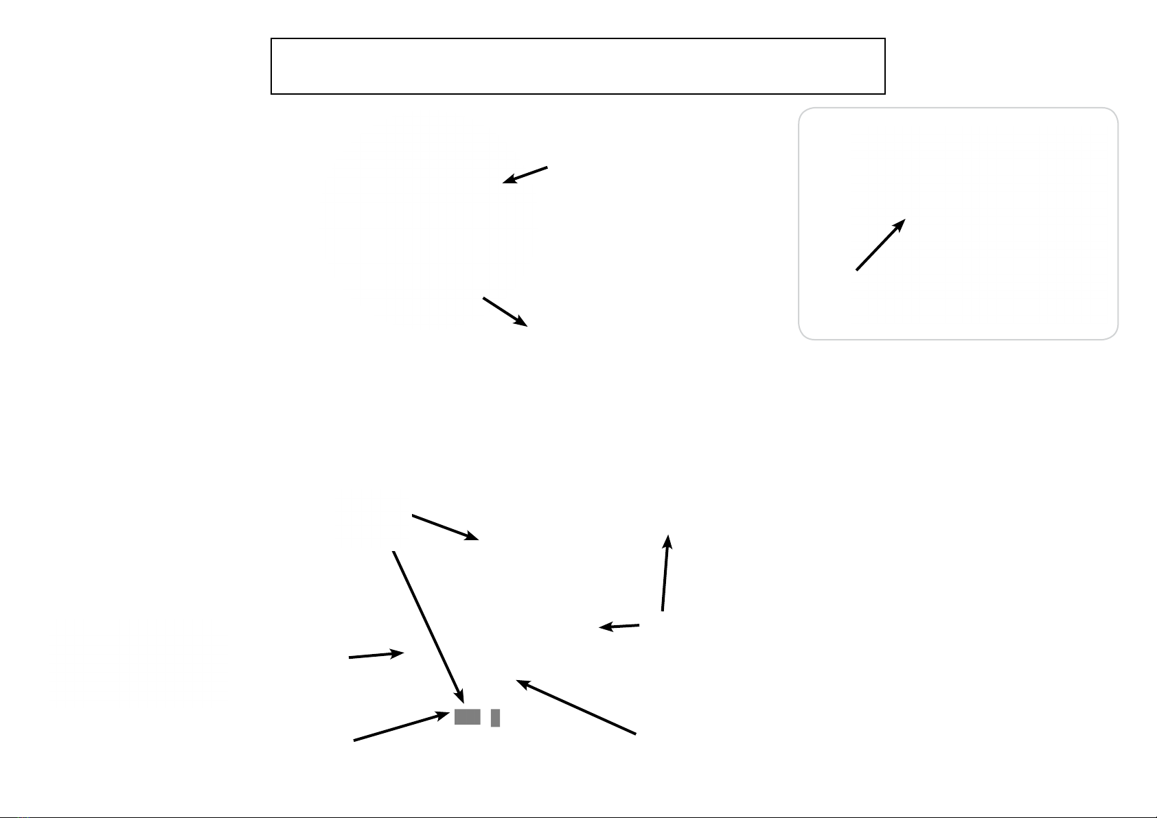
PIR VERSION:
To achieve best results we suggest you take the
following points into consideration:
Do not mount on a surface that has vibration.
Ideally the PIR tting should be mounted 1.8 to 2.5
metres (6 to 8ft) above the area to be scanned (refer
to Fig. 1 below).
To avoid damage to the unit do not aim sensor
towards the sun.
Avoid positioning the sensor unit adjacent to a
bright light source which may prevent the unit from
operating in dark conditions.
Avoid nuisance false triggering by directing sensor
away from:
Trees and shrubs
Reective surfaces such as smooth white walls
Swimming pools
Heat sources such as boiler ues
The PIR sensor scanning specications
(approximately 10 metres at 120°) may vary slightly
depending on the mounting height and location.
The detection range of the unit may also alter
with temperature change. Before selecting a place
to install your PIR tting you should note that
movement across the scan area is more eective
than movement directly towards or away from the
sensor (refer to Fig. 2 below).
If movement is made walking directly towards or
away from the sensor and not across the apparent
detection range will be substantially reduced (refer
to Fig. 3 below).
120˚
Approx
1.8-2.5m
10m Max
Fig 1
EFFECTIVE:
Movement across
scan area
LESS EFFECTIVE:
Movement
directly in front
of scan area
Fig 2
Fig 3
TROUBLESHOOTING AND USER HINTS:
Note: all passive infra red detectors are more sensitive in cold and dry weather than warm and wet weather.
PROBLEM POSSIBLE CAUSE SUGGESTED REMEDY
Light does not switch on
when there is movement
in the detection area.
1. No mains voltage Check all connections, and MCB Fuses / switches
2. Nearby lighting is too bright Relocate the unit
3. Wired incorrectly Check wiring and conrm its wired as per the
wiring diagram
Light switches on for no
apparent reason (false
trigger)
1. Heat sources such as air-con, vents, heaters, ues,
other outside lighting, moving cars trees or shrubs
are activating sensor Relocate tting
2. Animals / birds activating sensor Relocate tting
3. Interference from on/o switching of electric fans
or lights on the same circuit as your tting.
(This problem does not always occur but a faulty
switch may cause the tting to switch on)
Should the false triggering become, troublesome,
consider:
(a) Replacing a faulty switch
(b) Connecting the tting to a separate circuit (in
most cases where one or more of the above
suggestions have been carried out, false
triggering has been reduced)
4. Reection from swimming pool, or reective
surface such as smooth white walls Relocate tting
Light remains on
Continuously false triggered Relocate tting
Possible heat source in detection zone Cover PIR sensor lens with a thick cloth, if the
light turns o check detection area for heat or
reective source, reposition head