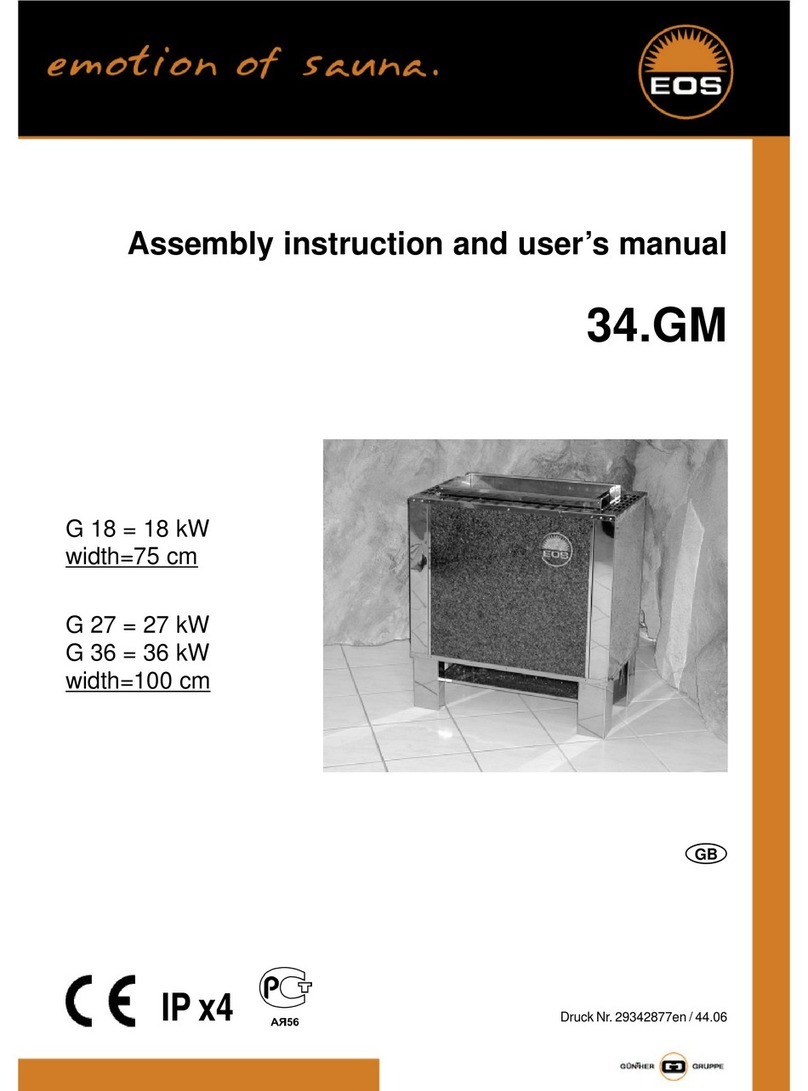
EOS 34.G Series Instruction Manual

Montage- und Gebrauchsanweisung
für Elektro-Saunaofen
34.G
G 15 = 15 kW
G 18 = 18 kW
G 21 = 21 kW
Breite=75 cm
G 24 = 24 kW
G 27 = 27 kW
G 30 = 30 kW
G 36 = 36 kW
Breite=100 cm
5 x 4²
5 x 6²
5 x 10²
mind.
5 x 10²
12
15
18
21
24
27
30
36
4 4-6 6-8
7-10
9-14
14-18 18-25 24-30
24-34 35-40 40-50 50-65 65-75
Heiz-
leistung
in kW
Anschluss an
400V 3N AC
Absicherung
A
3 x 25
3 x 35
3 x 50
3 x 63
Mindestquerschnitt der Netzzuleitung
in mm²
Erforderliche Heizleistungen und Anschlusswerte
Kabinengröße in m³ (Grundlage Fertigung nach RAL für Kabinen in Gebäuden)
Druck Nr. 29340727 / 52.04 20008585
IP x4 Tabelle 1

2
Wichtige Hinweise
Während dem Betrieb Ihrer Sauna-Anlage entstehen in
der Kabine und vor allem am Ofen sehr hohe Tempera-
turen. Bei unsa hgemäßer Montage besteht Brandge-
fahr! Lesen Sie bitte diese Montageanleitung sorgfältig
dur h. Bea hten Sie besonders die Maßangaben und
die na hfolgenden Hinweise.
lDas Saunaheizgerät ist für eine Ansch uss-Spannung
von 400 V AC 3N vorgesehen.
lDie Montage und der Ansch uss des Saunaheizgerä-
tes, Steuergerätes und anderer e ektrischer Betriebs-
mitte dürfen nur durch einen Fachmann erfo gen.
Hierbei sind besonders die notwendigen Schutzmaß-
nahmen nach VDE 0100 v. § 49 DA/6 und VDE 0100 Tei
703/11.92 § 4 zu beachten.
lSaunaheiz- und Steuergerät dürfen nur in Saunakabinen
aus geeignetem, harzarmen und unbehande tem
Materia (z.B. Nordische Fichte) verwendet werden.
lDie Mindesthöhe der Saunakabine muss innen
2,10 m betragen.
lIn der Saunakabine darf nur ein Saunaofen mit der er-
forder ichen Heiz eistung montiert werden (siehe Ta-
be e 1).
lIn jeder Saunakabine sind Be- und Ent üftungs-
öffnungen vorzusehen. Die Be üftungsöffnungen müs-
sen immer hinter dem Saunaheizgerät, ca. 5 bis 10 cm
über dem Fußboden angeordnet werden. Die Mindest-
maße der Be- und Ent üftungsöffnungen entnehmen
Sie der Tabe e 2.
lDie Ent üftung wird immer diagona versetzt zum
Saunaheizgerät in der hinteren Saunawand im unte-
ren Bereich angebracht. Die Be- und Ent üftung darf
nicht versch ossen werden. Bitte beachten Sie die Hin-
weise Ihres Saunakabinen ieferanten.
lA htung: Bede kung und ni ht vors hriftsmäßig gefüll-
ter Steinbehälter verursa ht Brandgefahr.
Vergewissern Sie si h vor jeder Inbetriebnahme, dass
keine Gegenstände auf dem Saunaheizgerät abge-
legt wurden.
lA htung: Während des Betriebes auftretende hohe
Temperaturen am Saunaheizgerät können bei Berüh-
rung zu Verbrennungen führen.
lDas Saunaheizgerät ist nicht für den Einbau oder Auf-
ste ung in einer Nische, unter der Bank oder unter ei-
ner Dachschräge bestimmt.
lDas Saunaheizgerät nicht bei gesch ossener Luftein-
trittsöffnung in Betrieb nehmen.
lDie Kabinenbe euchtung mit der dazugehörenden In-
sta ation muss in der Ausführung "spritzwasserge-
schützt" und für eine Umgebungstemperatur von 140°C
geeignet sein. Daher ist in Verbindung mit dem Sauna-
heizgerät nur eine VDE-geprüfte Sauna euchte mit max.
40 Watt zu insta ieren.
lDie Sauna-Einri htung (Saunaheizgerät, Steuergerät,
Beleu htung usw.) darf nur dur h einen örtli h zuge-
lassenen Elektroinstallateur mittels festem Ans hluss
an das Netz anges hlossen werden. A e Ansch uss-
eitungen, die im Inneren der Kabine ver egt werden,
müssen für eine Umgebungstemperatur von minde-
stens 140°C geeignet sein. Zweckmäßig ist eine Si ikon-
eitung. Werden a s Ansch uss eitung einadrige Leitun-
gen verwendet, müssen diese durch ein biegsames
Meta rohr geschützt werden. Den Mindestquerschnitt
der Ansch uss eitung und die geeignete Kabinengröße
im Verhä tnis zur Ansch uss eistung in kW entnehmen
Sie der Tabe e 1.
lBei der Montage des Saunaofens ist darauf zu achten,
dass der senkrechte Abstand zwischen Oberkante
Saunaofen und Saunadecke mindestens 130 cm und
der waagerechte (seit iche) Abstand zwischen Ofen
und Kabinenwand oder anderen brennbaren Materia-
ien mindestens 10 cm beträgt. Es ist zu beachten, dass
der Ofen nicht auf einen Boden aus eicht brennbarem
Materia (Ho z, Kunststoffbodenbe ag o.ä.) geste t wer-
den darf. Zweckmäßig im Saunabereich sind Keramik-
f iesen o.ä.
lDer Abstand zwischen Ofenschutzgitter bzw. Liegebank
und anderer brennbarer Materia ien zum Ofen muss
mindestens 10 cm betragen. Die Schutzgitter-Höhe
muss mit der vorderen Ofenhöhe g eich sein.
lZu verwenden mit a en EOS-Steuergeräten, die mit
zusätz ichem Leistungsscha tgerät betrieben werden
können.
15,0
18,0
21,0
24,0
27,0
30,0
36,0
Anschlussleistung
in kW
Mindestmaße der Be
und Entlüftung in cm *)
100 cm
(75 cm)
10 cm
80 cm mindestens 130 cm
10 cm
43 cm
10 cm
Tabelle 2
50 x 6 cm
50 x 6 cm
50 x 8 cm
50 x 8 cm
50 x 9 cm
50 x 10 cm
50 x 10 cm
* oder nach Angabe des Kabinenherstellers

Saunasteine
Der Saunastein ist ein Naturprodukt. Überprüfen Sie die
Saunasteine in rege mäßigen Abständen. Die Sauna-
steine können insbesondere durch scharfe Aufguß-
konzentrate angegriffen werden und sich im Laufe der
Zeit zersetzen. Fragen Sie ggf. Ihren Sauna-Lieferanten.
Die mitge ieferten Saunasteine unter f ießendem Wasser
gründ ich waschen und in den Steinbehä ter so ein egen, dass
die Konvektions uftströmung gut zwischen den Steinen zirku-
ieren kann.
Die Menge der Aufgusssteine reicht aus, um einen
Dampfstoß zu erzeugen, bei dem ca. 10 c Wasser je m³
Kabinenvo umen verdampft werden. Warten Sie nach
jedem Aufguss ca. 10 Min. bis zum nächsten Aufguss.
Erst dann haben sich die Saunasteine wieder ausreichend
erhitzt.
Geben Sie dem Aufgusswasser nie mehr Aufgussmitte
oder ätherische Ö e bei, a s auf diesen Gebinden ange-
geben. Verwenden Sie niema s A koho oder unverdünnte
Konzentrate. Achtung! Brandgefahr.
BITTE DRINGEND BEACHTEN!
Steine im Steinbehälter des Saunaofens nicht
aufschichten, sondern grob auflegen, damit
möglichtst viele Zwischenräume für die
durchströmende Heißluft verbleiben.
Allgemeine Hinweise
Beachten Sie, dass Sie ein optima es Saunak ima nur dann
erreichen, wenn die Kabine mit ihrer Zu uft und Ab uft,
das Saunaheizgerät und das Steuergerät aufeinander
abgestimmt sind.
Beachten Sie die Angaben und Informationen Ihres Sau-
na-Lieferanten.
Die Saunaheizgeräte erwärmen Ihre Saunakabine durch
aufgeheizte Konvektions uft. Dabei wird Frisch uft aus der
Zu uftöffnung angesaugt, die durch das Erwärmen nach
oben steigt (Konvektion) und dann in der Kabine umge-
wä zt wird. Ein Tei der verbrauchten Luft wird durch die
Ab uftöffnung in der Kabine nach außen gedrückt.
Hierdurch entsteht das typische Saunak ima bei dem in
Ihrer Sauna direkt unter der Decke Temperaturen von ca.
110°C erreicht werden, die durch das Temperaturgefä e
in der Kabine auf ca. 30-40°C im Fußbereich sinken. Da-
her ist es nicht ungewöhn ich, wenn z.B. am Temperatur-
füh er über dem Ofen 110°C herrschen, das Thermome-
ter, we ches ca. 20-25 cm unter der Kabinendecke an der
Saunawand montiert ist, aber nur 85°C anzeigt. In der
Rege iegt die Badetemperatur bei max. Temperaturein-
ste ung im Bereich der oberen Liegebank zwischen 80°C
und 90°C.
Beachten Sie, dass in der Kabine immer über dem Sau-
naheizgerät die höchsten Temperaturwerte entstehen und
dort auch die Temperaturfüh er und Sicherheitsbegrenzer
anzubringen sind.
Beim ersten Aufheizen kann es zu einer eichten Geruchs-
bi dung durch Verdunsten von Betriebsstoffen aus den
Fertigungsprozessen kommen. Lüften Sie nach diesem
Vorgang Ihre Kabine, bevor Sie mit dem Saunabad be-
ginnen.
3

4
Verdrahtungsschema für Saunaöfen 1 - 7 kW mit Lastaufteilung auf Steuergerät und Leistungsschaltgerät
Verdrahtungsschema für Saunaöfen bis 36 kW ohne Lastaufteilung
L3 L2 L1 S2 S1 U V W N N N
Sauna-Steuergerät
Fühler
Begrenzer
Saunaofen bis 27 kW
4 3 2 1
N U1 V1 W1
max. 9 kW max. 18 kW
N U2 V2 W2
4 3 2 1
Leistungsschaltgerät LSG 18 90 7372 00
Sicherheitsschütz
N N
Sicherheitsschütz
5 x 1,5²
2 x 1,5²
5 x 2,5² 5 x 6²
Abzweigkasten
Netzschalter
3 x 16 A
12-16 kW: 4²
18-21 kW: 6²
24-27 kW: 10²
L1 L2 L3 N
L3 L2 L1
Sauna-Steuergerät
S1 U V W
N
Fühler
Begrenzer
Begrenzer
Temperaturfühler
Fühlergehäuse
3 x 1,5²
3 x 1,5²
30 kW: 10 mm²
36 kW: 10 mm²
Netzschalter
Regelschütz B
Sicherheitsschütz
Regelschütz A
Leistungsschaltgerät bis 36 kW 90 8771 00
L1 L2 L3 N N N S1 A B
N
U1 V1 W1
4 3 2 14 3 2 1
Saunaofen
max. 18 kW
N
U2 V2 W2
max. 18 kW
Ausgang:
Sicherheitsschütz

Ans hlusspläne
5

6
Hinweis
Ableitstrom bei Saunaheizgeräten
Bei der Insta ation von Saunaheizgeräten ist die DIN VDE
0100 Tei 703 zu beachten!
Diese Norm macht in Ihrer neuesten Ausgabe, gü tig seit
Juni 1992, unter Änderungen Absatz (f) fo gende Aussa-
ge; Zitat:
Die Forderung nach Fehlerstrom-Schutzeinrichtungen für
Betriebsmittel der Schutzklasse I als Alternative zur Schutz-
kleinspannung ist entfallen.
Die EN 60335-1 DIN VDE 0700 Tei 1 vom Januar 2001
besagt unter Absatz 13 fo gendes; Zitat:
Der Ableitstrom darf bei Betriebstemperatur folgende
erte nicht überschreiten:
- bei ortsfesten ärmegeräten der Schutzklasse I 0,75
mA; oder 0,75 mA je k
Bemessungsaufnahme des Gerätes, je nachdem, wel-
cher ert größer ist, mit einem Höchstwert von 5 mA.
So te jedoch eine Feh erstrom-Schutzeinrichtung (FI-
Schutzscha ter) eingebaut werden, so ist darauf zu ach-
ten, dass keine weiteren e ektrischen Verbraucher über
diesenFI-Schutzscha ter abgesichert werden.
Nach dem heutigen Stand der Technik können noch kei-
ne Rohrheizkörper für Saunaöfen hergeste t werden, die
aus der Umgebungs uft keine Feuchte an den Enden an-
ziehen. Dadurch kann beim Aufheizen ein kurzzeitig er-
höhter Feh erstrom auftreten.
So te a so bei Inbetriebnahme der FI-Schutzscha ter aus-
ösen, muss die e ektrische Insta ation nochma s über-
prüft werden.
Es ist jedoch auch mög ich, dass sich die Magnesiumoxid-
fü ung in den Heizstäben beim Lagern oder Transport mit
Feuchte aus der Umgebungs uft angereichert hat und nun
beim Aufheizen zum Aus ösen des FI-Schutzscha ters führt.
Dies ist ein physika ischer Vorgang und kein Feh er des
Herste ers.
In diesem Fa muss der Ofen von einem Fachmann unter
Aufsicht aufgeheizt werden, wobei der Schutz eiter nicht
angek emmt ist. Nachdem die Feuchte nach ca. 10 min.
aus den Heizstäben entwichen ist, muss der Ofen wieder
mit dem Schutz eiter verbunden werden!
So te der Saunaofen über ängere Zeit nicht benutzt wer-
den, so empfeh en wir ein Aufheizen ca. a e 6 Wochen,
damit sich die Heizstäbe nicht mit Feuchte anreichern
können.
Für den ordnungsgemäßen Ansch uss der Heizgeräte ist
der E ektroinsta ateur verantwort ich und somit ist eine
Haftung durch den Herste er ausgesch ossen!
Gewährleistung
Die Gewähr eistung wird nach den derzeit gü tigen ge-
setz ichen Bestimmungen übernommen.
Herstellergarantie
- Die Garantiezeit beginnt mit dem Datum des Kauf-
be egs und dauert grundsätz ich 12 Monate.
- Garantie eistungen erfo gen nur dann, wenn der zum
Gerät gehörige Kaufbe eg vorge egt werden kann.
- Bei Änderungen am Gerät, die ohne ausdrück iche
Zustimmung des Herste ers vorgenommen wurden,
verfä t jeg icher Garantieanspruch.
- Für Defekte, die durch Reparaturen oder Eingriffe von
nicht ermächtigten Personen oder durch unsachge-
mäßen Gebrauch entstanden sind, entfä t ebenfa s
der Garantieanspruch.
- Bei Garantieansprüchen ist sowoh die Seriennummer
sowie die Artike nummer zusammen mit der Geräte-
bezeichnung und einer aussagkräftigen Feh er-
beschreibung anzugeben.
- Diese Garantie umfasst die Vergütung von defekten
Gerätetei en mit Ausnahme norma er Versch eiß-
erscheinungen.
Bei Beanstandungen ist das Gerät in der Origina -
verpackung oder einer entsprechend geeigneten Verpa-
ckung (ACHTUNG: Gefahr von Transportschäden) an un-
sere Service-Abtei ung einzuschicken.
Senden Sie das Gerät stets mit diesem ausgefü ten Ga-
rantieschein ein.
Eventue entstehende Beförderungskosten für die Ein-
und Rücksendung können von uns nicht übernommen
werden.
Außerha b Deutsch ands wenden Sie sich im Fa e eines
Garantieanspruches bitte an Ihren Fachhänd er. Eine di-
rekte Garantieabwick ung mit unserem Servicecenter ist
in diesem Fa nicht mög ich.
Inbetriebnahme am:
Stempe und Unterschrift des
autorisierten E ektroinsta ateurs:
"
Achtung!
Sehr geehrter Kunde,
na h den gültigen Vors hriften ist der elektris he An-
s hluss des Saunaofens sowie der Saunasteuerung nur
dur h einen Fa hmann eines autorisierten Elektrofa h-
betriebes zulässig. Wir weisen Sie daher bereits jetzt
darauf hin, dass im Falle eines Garantieanspru hes eine
Kopie der Re hnung des ausführenden Elektrofa h-
betriebes vorzulegen ist.

Instructions for Installing and Operating
the 34.G Electric Sauna Sto e
34.G
G 15 = 15 kW
G 18 = 18 kW
G 21 = 21 kW
Width=75 cm
G 24 = 24 kW
G 27 = 27 kW
G 30 = 30 kW
G 36 = 36 kW
Width=100 cm
5 x 4²
5 x 6²
5 x 10²
min.
5 x 10²
12
15
18
21
24
27
30
36
4 4-6 6-8
7-10
9-14
14-18 18-25 24-30
24-34 35-40 40-50 50-65 65-75
Heat
output in
kW
Connection to
400 V 3N AC
FuseA
3 x 25
3 x 35
3 x 50
3 x 63
Min. cross-section of the mains cable in
mm2
Required heat outputs and connection ratings
Cabin size in m3(manufacture conforms to RAL for cabins inside buildings)
IP x4
7
Table 1

8
Special Instructions
During operation of the sauna, very high temperatures
are reated within the abin and parti ularly at the sto-
ve. If the stove is not installed orre tly there will be a
fire hazard. Please read these installation instru tions
arefully. You should pay parti ular attention to the
spe ified measurements and to the instru tions below.
lThe sauna heating unit is designed for operation with
an input vo tage of 400 V AC 3N through the sauna
contro unit.
lInsta ation and e ectrica connection of the sauna
heating units, the contro unit and other e ectrica
components must be performed by a qua ified
e ectrician. The specia safety requirements specified
in VDE 0110 v. § 49 DA/6 and VDE 0100, Part 703/11.92 §
4 must be observed during e ectrica insta ation.
lThe sauna heating and contro units may be used on y
in sauna cabins constructed of suitab e, resin-free,
untreated materia (e.g. Nordic spruce).
lThe sauna cabin must have a minimum inside height
of 2.10 m.
lOn y one sauna heater providing the required heating
output may be insta ed in the sauna cabin (see Tab e 1).
lEvery sauna cabin must have a fresh-air in et and an
exhaust out et. A venti ation in ets/out ets must be
positioned behind the sauna heating unit and approx.
5-10 cm above the f oor. Minimum in et/out et
dimensions are isted in Tab e 2.
lThe exhaust out et must be positioned in the ower
section of the rear wa of the sauna cabin, diagona y
opposite the sauna heating unit. Fresh-air in ets and
exhaust out ets must not be c osed. P ease observe
the instructions provided by your sauna cabin supp ier.
lCaution: Covered or improperly filled stone grates an
ause fire hazards.
Please ensure that no obje ts have been left lying on
the sauna heating unit prior to ea h operation.
lCaution: Due to the high temperatures generated
during operation of the sauna heating unit, direct
contact with the unit can cause burns.
lThe sauna heating unit is not designed for insta ation/
use in a niche, beneath the rec ining bench or beneath
an inc ined cei ing.
lThe sauna heating unit must not be operated when the
fresh-air in et is c osed.
lCabin ighting and ighting insta ation components
must be sp ash-resistant and suitab e for operation at
environmenta temperatures of up to 140°C. Therefore,
on y VDE-tested sauna ighting systems (max. 40 Watt)
may be used in connection with the sauna heating
unit.
lThe omplete sauna system (sauna heating unit,
ontrol unit, lighting system, et .) may be onne ted
to the main power system by a lo ally ertified
ele tri ian only. A e ectrica wiring insta ed inside the
cabin must be suitab e for use at environmenta
temperatures of up to 140° C. Si icone cab es are
recommended. If sing e fi ament cab es are used, they
must be protected with f exib e meta tubing. Minimum
diameters for connection cab es and suitab e cabin
sizes for specific heating output va ues in kW are isted
in Tab e 1.
lWhen insta ing the sauna heater, p ease ensure that
the vertica height between the top surface of the sauna
heater and the roof of the sauna is at east 130 cm, and
that the horizonta separation between the heater and
the cabin wa or other f ammab e materia s is at east
10 cm. Ensure that the heater is not p aced on a f oor
made from high y f ammab e materia s (e.g. wood,
p astic f ooring). Ceramic ti es or simi ar are most
suitab e for the sauna area.
lThe distance between the heater guard and/or bench
and other f ammab e materia s must be at east 10 cm.
The height of the heater guard must be the same as
the height of the front of the stove.
lTo be used with a EOS sauna contro units suitab e for
additiona power contro units.
100 cm
(75 cm)
10 cm
80 cm minimum 130 cm
10 cm
43 cm
10 cm
15,0
18,0
21,0
24,0
27,0
30,0
36,0
Power input
in kW
Minimum dimensions of
fresh air inlets and exhaust
outlets in cm *)
Table 2
50 x 6 cm
50 x 6 cm
50 x 8 cm
50 x 8 cm
50 x 9 cm
50 x 10 cm
50 x 10 cm
* oder nach Angabe des Kabinenherste ers

Sauna stones
Sauna stones are natura materia s. Check your sauna
stones at regu ar interva s, since they are susceptib e to
the effects of strong steam-water additives and may
decompose over a ong period of time. Consu t your sauna
supp ier if you have any questions.
The sauna stones de ivered with your sauna heating
system shou d be washed thorough y in running water
and p aced in the stone grate in such a way that the
convection-air can f ow free y between the stones.
The quantity of sauna stones is sufficient to vaporize
approx. 10 c of water per cubic meter of cabin space.
Wait for about 10 minutes after each pouring before adding
water again. This a ows the stones to heat up sufficient y.
Never add more additives or etherea oi s to the steam
water than is indicated on the containers. Never use
a coho or undi uted concentrates. Caution! Fire hazard.
RGENT WARNING!
Stones must not be piled in layers in the stone
grate on the sauna heater but instead
placed in a loose arrangement in order to
ensure that rising hot air can flow freely
between the stones.
General instructions
P ease note that optimum sauna c imate conditions can
be achieved on y if the cabin venti ation (fresh air and
exhaust) system, the sauna heater and the contro unit
are designed and set to work efficient y in combination.
P ease observe the instructions and information
provided by your sauna supp ier.
Sauna heating units heat your sauna cabin with warmed
convection air. Fresh air drawn by suction pressure
through the fresh-air in et is heated, rises upward
(convection) and is then circu ated within the cabin.
Some of the consumed air is forced out of the cabin
through the exhaust out et. This process produces a
typica sauna c imate, with temperatures of
approximate y 110° C immediate y be ow the cei ing
and a temperature gradient that produces ow
temperatures of approximate y 30-40° C at f oor eve .
Thus it is not unusua for the temperature sensor above
the heater to register 110° C, whi e the thermometer
mounted on the sauna wa approximate y 20-25 cm
be ow the cabin cei ing shows on y 85° C. Ordinari y,
sauna temperatures range between 80° C and 90° C at
the eve of the upper rec iner bench at the maximum
temperature setting.
P ease remember that temperatures are a ways at their
highest just above the sauna heating unit and ensure
that temperature sensors and safety imiters are
mounted there.
When the unit is heated up for the first time, evaporation
of residua substances from the production process may
cause s ight odors. The cabin shou d be aired out
thorough y before you begin your sauna bath.
9

10
Wiring diagram for 1 - 7 kW sauna stove with load distribution to control unit and power control unit
Wiring diagram for sauna heaters to 36 kW without load distribution
L3 L2 L1 S2 S1 U V W N N N
Sauna control unit
sensor
limiter
Sauna heater up to 27 kW
4 3 2 1
N U1 V1 W1
max. 9 kW max. 18 kW
N U2 V2 W2
4 3 2 1
Power control unit LSG 18 90 7372 00
safety contactor
N N
safety contactor
5 x 1,5²
2 x 1,5²
5 x 2,5² 5 x 6²
junction box
Mains switch
3 x 16 A
12-16 kW: 4²
18-21 kW: 6²
24-27 kW: 10²
L1 L2 L3 N
L3 L2 L1
Sauna-Steuergerät
S1 U V W
N
sensor
limiter
Limiter
Temperature sensor
Sensor housing
3 x 1,5²
3 x 1,5²
30 kW: 10 mm²
36 kW: 10 mm²
Mains switch
Control contactor B
Safety contactor
Control contactor A
Power control unit to 36 kW 90 8771 00
L1 L2 L3 N N N S1 A B
N
U1 V1 W1
4 3 2 14 3 2 1
Sauna heater
max. 18 kW
N
U2 V2 W2
max. 18 kW
Outlet:
Safety contactor

Terminal onne tion diagrams
11
to 9 kW power control unit
to 6 kW control unit
1234
to 9 kW power control unit
to 9 kW control unit
to 9 kW power control unit
to 9 kW control unit
5 x 1,5
2
5 x 1,5
2
5 x 1,5
2
5 x 1,5
2
5 x 2,5
5 x 1,5
2
3,0 kW
3,0 kW
3,0 kW
3,0 kW
3,0 kW
3,0 kW
3,0 kW
15 kW 18 kW
21 kW
2
NWVU
PEPE
4321
UVWN
W
PE
43
N
21
UV
PE
4
N
321
VWU
3,0 kW
3,0 kW
3,0 kW
3,0 kW
3,0 kW
3,0 kW
3,0 kW
3,0 kW
3,0 kW
3,0 kW
3,0 kW
N
PE
4321
VWU
PE
U
4321
WNV
to 18 kW power control unit
to 18 kW control unit
5 x 1,5
2
5 x 4
2
36 kW
3,0 kW
N
PE
4321
VWU
PE
U
4321
WNV
55
3,0 kW
3,0 kW
3,0 kW
3,0 kW
3,0 kW
3,0 kW
3,0 kW
3,0 kW
3,0 kW
3,0 kW
3,0 kW
3,0 kW
3,0 kW
3,0 kW
PE
45231
3,0 kW
3,0 kW
3,0 kW
3,0 kW
3
PE
54 21
3,0 kW
3,0 kW
to 9 kW control unit
to 18 kW power control unit
27 kW
NVWU
5 x 1,5
2
NWVU 5 x 4
2
2
3,0 kW
3,0 kW
3,0 kW
PE
453
3,0 kW
3,0 kW
3,0 kW
1
PE
5432
3,0 kW
3,0 kW
1
24 kW
NW V
to 9 kW control unit
to 15 kW power control unit
5 x 1,5
VU
2
NW 5 x 4
U
2
3,0 kW
3,0 kW
3,0 kW
3,0 kW
3,0 kW
5
PE
3412
3,0 kW
3,0 kW
3,0 kW
3,0 kW
PE
24531
3,0 kW
to 15 kW power control unit
to 15 kW control unit
30 kW
WNVU
5 x 4
2
NWVU 5 x 4
2

12
Information
Sauna heaters and leakage urrent
DIN VDE 0100 Part 703 shou d be observed when
insta ing sauna heaters.
In its most recent version, app icab e since June 1992,
this standard states the fo owing under Amendments to
Paragraph (f):
The requirement for residual-current-operated protective
devices for protection class I equipment as an alternative
to Safety Extra Low Voltage no longer applies.
The EN 60335-1 DIN VDE 0700 Part 1 of January 2001
states the fo owing under Paragraph 13:
At operational temperature the leakage current should
not exceed the following values:
- non-portable heaters of protection class I 0.75 mA; or
0.75 mA per k of the appliance's rated power input,
whichever value is greater, to a maximum value of 5
mA.
However, if a residua -current-operated protective device
(a residua current circuit breaker) is bui t in, it shou d be
ensured that no other e ectrica oad is protected by this
residua current circuit breaker.
Techno ogy is sti not in a position to be ab e to
manufacture a heater for sauna stoves that does not attract
moisture from the ambient air to the ends. Therefore
when it heats up there may be a very brief, e evated
residua current.
If the residua current circuit breaker is tripped when the
app iance is turned on, the e ectrica insta ation needs
to be rechecked.
However, it cou d a so be that the magnesium oxide fi ing
in the heating rods has extracted moisture from the
ambient air during storage or transport, and when the
app iance heats up the residua current circuit breaker is
tripped.
In such a case, a technician shou d heat up the stove
with the ground wire detached, and monitor the
procedure. After the moisture is removed from the
heating rods after about 10 minutes, the stove shou d be
reconnected to the ground wire.
If the sauna stove is not going to be used for a ong
period, we recommend that it is heated up about every 6
weeks, so that the heating rods do not attract moisture.
The e ectrician is responsib e for connecting the heater
correct y, and the manufacturer therefore accepts no
iabi ity.
Warranty
The warranty may be transferred under the terms of the aw
app icab e at that time.
Manufa ture Guarantee
- The guarantee period begins from the date shown on
the purchase receipt and asts for 12 months.
- The guarantee wi on y be deemed va id upon
presentation of the app iance's purchase receipt.
- Any a terations made to the app iance without the
express permission of the manufacturer sha render a
warranty c aims inva id.
- Any fau ts arising due to repairs or actions carried out
by unqua ified persons or due to improper use a so
render a warranty c aims inva id.
- When submitting a warranty c aim, the customer must
quote the seria number, the item number, the app iance
name and a detai ed description of the fau t.
- This guarantee covers compensation for fau ty
components except for imperfections caused by nor-
ma wear and tear.
In the case of comp aints, the app iance shou d be sent to
our service department in its origina packaging or in other
suitab e packaging (PLEASE NOTE the danger of damage
during transport).
A ways send this guarantee form, fi ed in, with the
app iance.
We cannot assume any transport costs that may arise from
sending the app iance backwards and forwards.
If a warranty c aim arises outside Germany, p ease contact
your distributor. In such cases, there can be no direct
contact with our service centre about the guarantee.
Date of first operation:
Stamp and signature of the authorised e ectrician:
"
Attention!
Dear ustomer,
a ording to the valid regulations, the ele tri al
onne tion of the sauna heater and the ontrol box has
to be arried out through the spe ialist of an authorized
ele tri shop.
We would like to mention to the fa t that in ase of a
warrenty laim, you are kindly requested to present a
opy of the invoi e of the exe utive ele tri shop.

13

14
Other manuals for 34.G Series
1
This manual suits for next models
7
Table of contents
Languages:
Other EOS Stove manuals
Popular Stove manuals by other brands

Beltane Stoves
Beltane Stoves FW5C HOLFORD Installation and operating instructions

Lopi
Lopi Liberty owner's manual

EVA Stampaggi
EVA Stampaggi SILENCE 9 instruction manual

HASE
HASE Jena B.11 Instructions for use

Lincar
Lincar Alice 480N Using instructions

Mareli Systems
Mareli Systems ONYX AIR 8 KW Assembly and exploitation manual