Epcom EPIG1K User manual
EPIG1K / EPIG2K

Contents
1. Manual Instruction
1.1 Symbols used in this manual ........................................................................................................ 1
1.2 User group ................................................................................................................................... 2
1.3 Validity ......................................................................................................................................... 2
2. Safety Instructions
2.1 Intended use ................................................................................................................................ 2
2.2 Safety instructions ........................................................................................................................ 3
3. Unpacking
3.1 Scope of delivery.......................................................................................................................... 4
3.2 Identifying the Inverter.................................................................................................................. 4
4. Mounting the Device
4.1 Security........................................................................................................................................ 5
4.2 Selecting the mounting location .................................................................................................... 5
4.3 Mounting instructions.................................................................................................................... 7
5. Electrical Connection
5.1 Connection Area Overview ........................................................................................................... 9
5.2 System Diagram......................................................................................................................... 10
5.3 Cable Sizing............................................................................................................................... 11
5.4 Connection of the PV generator (DC).......................................................................................... 12
5.5 Connecting the inverter to the grid .............................................................................................. 13
5.6 Connecting communication cable ............................................................................................... 16
6. Switch on and off
6.1 Switch on ................................................................................................................................... 17
6.2 Switch off ................................................................................................................................... 17
7. Operation
7.1 Display Overview........................................................................................................................ 18
7.2 LED display................................................................................................................................ 18
7.3 LCD display................................................................................................................................ 19
8. Troubleshooting
8.1 Display Message........................................................................................................................ 23
9. Technical data...................................................................................................................... 29
10. Appendix
10.1 Exclusion of liability................................................................................................................... 31

<<1
1. Manual Instruction
1.1 Symbols used in this manual
This manual contains important instructions for safety and operation which must be
understood and carefully followed during installation and maintenance of the equipment.
In order to reduce the risk of electric shock and to be sure that the equipment is correctly
installed and ready to operate, special safety symbols are used in the manual to highlight
potential safety risks or useful information. The symbols are the following:
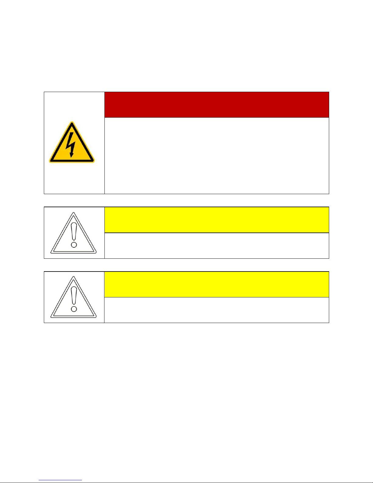
DANGER!
DANGER indicates a hazardous situation which, if not avoided,
will result in death or serious injury.
WARNING!
WARNING indicates a hazardous situation which, if not avoided,
could result in death or serious injury.
CAUTION!
CAUTION indicates a hazardous situation which, if not avoided,
could result in minor or moderate injury.
NOTICE
NOTICE indicates a situation which, if not avoided, could result
in property damage.
Information
Information provides tips that are valuable for the optimal
installation and operation of your product.

2>>
1.2 User group
This manual is for electrically skilled persons. The tasks described in this manual may
only be performed by electrically skilled persons.
1.3 Validity
This manual applies to EPIG1K / EPIG2K dirg
-
connected inverter and
describes the mounting, installation, commissioning, maintenance and troubleshooting
procedures.
Keep this manual in a convenient place for future reference.
2. Safety Instructions
2.1 Intended use
EPIG1K / EPIG2 is a PV inverter; which converts the direct current of the
PV array to grid-compliant alternating current and feeds it into the power distribution grid.
PV grid-connected system consists of PV modules, grid-connected inverters, metering
device and power distribution system (Figure 1).
Figure 1 PV grid-connected system
PV modules Combiner box
Inverter
Metering
Power grid

<<3
The EPIG1K / EPIG2K retrevniseirSe is suitable for indoor and outdoor
use and may only be operated with PV arrays (PV modules and cabling) of protection
class II... Do not connect any sources of energy other than PV modules to the inverter.
Any other use can result in personal injury or property damage.
2.2 Safety instructions
DANGER!
Danger to life due to high voltages in the inverter!
High voltages that can result in electrical shocks are present in the
conductive component parts of the inverter.
All work on the inverter may be carried out by qualified personnel
only.
DANGER!
Danger of burn injuries due to hot enclosure parts.
Do not touch enclosure during operation.
Only touch the lid during operation.
DANGER!
Before opening the housing, the inverter must be disconnected
from the grid and PV generator; while you must wait at least 5
minutes to let the energy storage capacitors fully discharged after
disconnecting from the power sources.
WARNING!
The installation must be performed in full compliance with
national and local standards and regulations.
4>>
WARNING!
Grounding the PV Generator
Be sure that the PV generator frame and inverter connect to the
ground in order to achieve maximum protection of the system and
personnel
3. Unpacking
3.1 Scope of delivery
Check the delivery for completeness and for any visible external damage. Contact your
dealer if anything is damaged or missing.
Object
Description
Quantity
A
EPIG1K / EPIG2K inverter
1
B DC plug connectors (1 x positive/1 x negative) 1 pair
C AC plug assembly 1
D Wall plug 4
E
Mounting screws
4
F
Mating connector for RS485 terminal block
2
G User manual 1
3.2 Identifying the Inverter
You can identify the inverter by the type label. The type label is on the right side of
the enclosure. The serial number (Serial No.) and the type (Type / Model) of the product,
as well as device-specific characteristics are specified on the type label.
<<5
4. Mounting the Device
4.1 Security
DANGER!
Danger to life due to fire or explosion!
• Despite careful construction, electrical devices can
cause fires.
• Do not mount the inverter on flammable construction materials.
• Do not install the inverter in areas where highly
flammable materials are stored.
• Do not install inverters in areas with a risk of explosion.
CAUTION!
Risk of injury due to the heavy weight of the inverter.
• Take the weight of the inverter into account for transport.
• Select a suitable mounting location and mounting surface.
CAUTION!
Danger of burn injuries due to hot enclosure parts!
Mount the inverter in such a way that it cannot be touched
inadvertently.
4.2 Selecting the mounting location
Consider the following requirements when selecting the mounting location:
The mounting method and location must be suitable for the inverter's weight
and dimensions (see section 11 "Technical Data" (page 80)).
Mount on a solid surface.
The mounting location must at all times be clear and safely accessible.
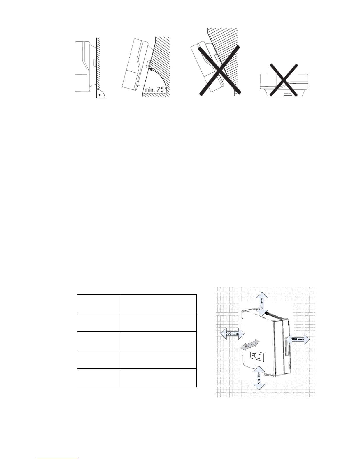
Mount vertically or tilted backwards by max. 15°.
6>>
The connection area must point downward.
Never mount the device with a forward tilt...
Never install the device with a sideways tilt.
Do not mount horizontally...
Mount at eye level to allow operating states to be read at all times.
The ambient temperature should be below 40°C to ensure optimum operation.
Do not expose the inverter to direct sunlight as this can cause excessive
heating and thus power reduction.
In living areas, do not mount the unit on plasterboard walls or similar to avoid
audible vibrations. When in use, the inverter emits noises which may be
perceived as a nuisance in a living area.
Observe the following minimum clearances to walls, other devices or objects
to guarantee sufficient heat dissipation and enough space for pulling the
Electronic Solar Switch handle.
Direction
Minimum clearance
Sides
300 mm
Above
300 mm
Below
500 mm
Front
50 mm
<<7
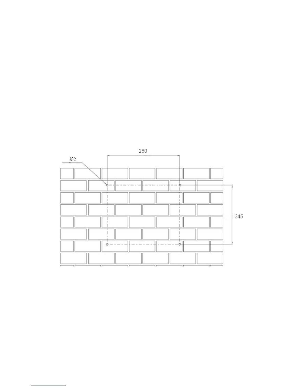
4.3 Mounting instructions
Mounting procedures:
a) Drilling holes:
There are holes on the mounting template in the accessory, which is for help of
orientation. Drill four holes for the screws at the selected installation position. The space
between every two holes is shown in the figure below. Keep drilling vertical to the wall
and don’t shake the drill to avoid holes tilting. The depth of the holes must be the same
and 55mm~60mm. After removing the dust in the four holes, measure the net depth of
the holes. If the depth is deeper than 60 mm or less than 55 mm, the wall plugs wouldn’t
be installed and tightened.
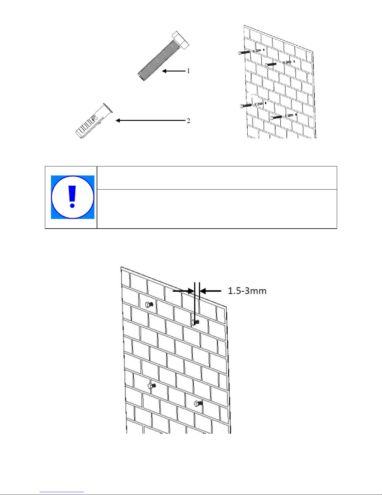
b) Wiring the screws
After drilling holes in the wall, place four wall plugs (object2 shown in the left drawing
below) in the holes using a rubber hammer. Then, wiring four screws (object1) into the
wall plugs.
8>>
NOTICE
Before inserting wall plugs, measure the depth of every hole and
the distance between every two holes. If the measured values do
not meet the installing requirements, re-drill holes in the wall.
c) Attach the inverter to the screws downwards slightly.

<<9
5. Electrical Connection
5.1 Connection Area Overview
The following figure shows the assignment of the individual connection areas on the
bottom of the inverter.
AB C
10>>
Object Description
A DC input: Plug-in connectors for connecting the PV strings
B Communication connection area: PV inverters are configured via RS485
interface.
C AC output: Socket for grid connection
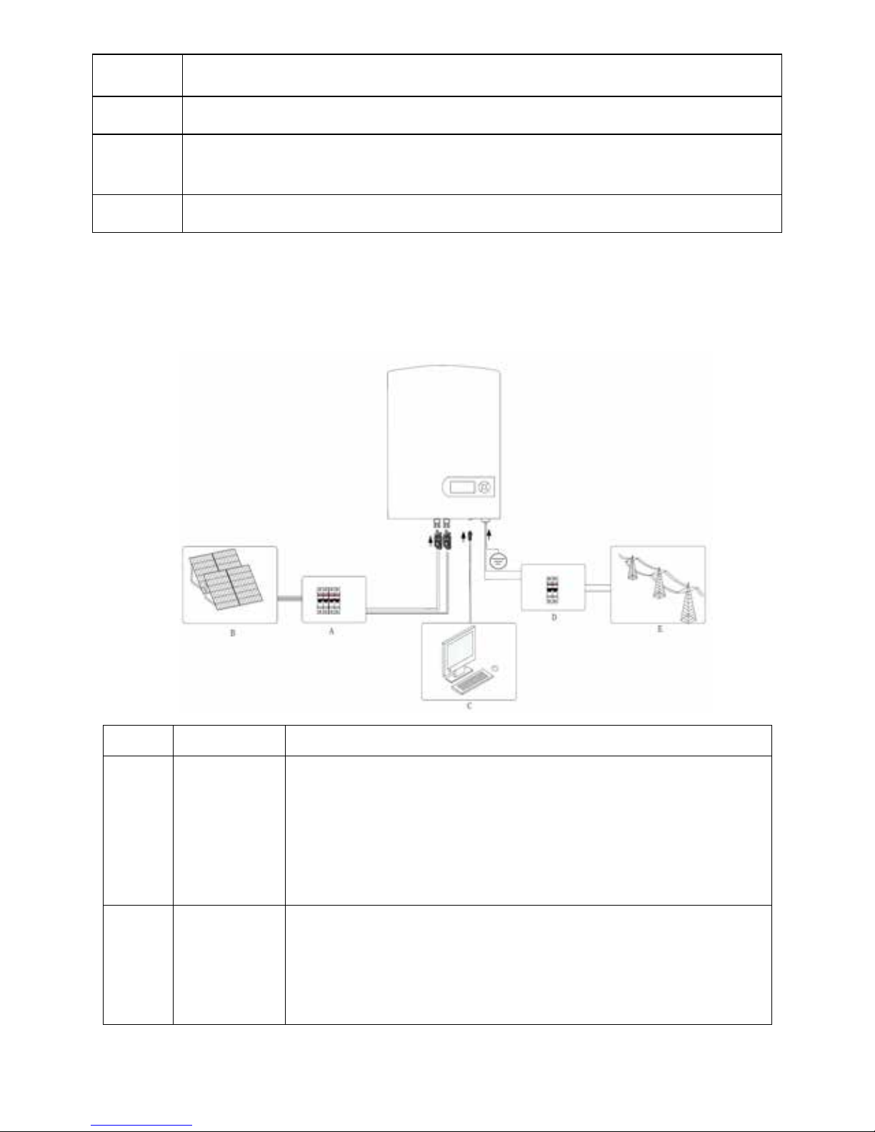
5.2 System Diagram
The typical connection diagram for the entire PV system is shown in the following figure.
Object Item Description
A DC circuit
breaker
Used as a protective device during electrical connection. User
must equips this device according to the maximum input
voltage and current. You must choose the external DC circuit
breaker whose rated current is 20A and the max breaking
capacity can reach more than 1kA.
B PV arrays
Provide DC power to the inverter. The allowable maximum
open-circuit voltage of the PV arrays is 550V and maximum
short-circuit currents 13.5A for EPIG1K /
15.5A for EPIG2K

<<11
C Remote PC User equips this device to monitor the state of the inverter.
D AC circuit
breaker
Used as a protective device during electrical connection. You
must choose the external AC circuit breaker whose rated
current is 20A and the max breaking capacity can reach more
than 2kA. The PE cable should be connected reliably to the
earth.
E Grid Rated voltage of the utility grid is 230V.
5.3 Cable Sizing
All cables for PV power system are equipped with water-proof direct plug-in connectors.
You‘ll nd t hese connectors in the package
For electrical connection in the PV system described above, the cross section of all
cables used should not be smaller than the following requirements.
AC Output DC Input
L N PE + -
EPIG1K 14 14 14 12 12
EPIG2K 12 12 12 11 11
There is only one channel of DC input which can connect one PV string. The red is
“+”, and the black is “ -”. There is one c hannel of AC output, the red is L phase, the black
is N phase,and the yellow-green is PE.
NOTICE
The grid impedance of the AC cable must not exceed 1 Ohm. Otherwise, the
inverter will disconnect at full feed capacity due to excessive voltage at the feed-
in point.
Wire Size
(mm)
AWG
Model
Terminal
s
12>>
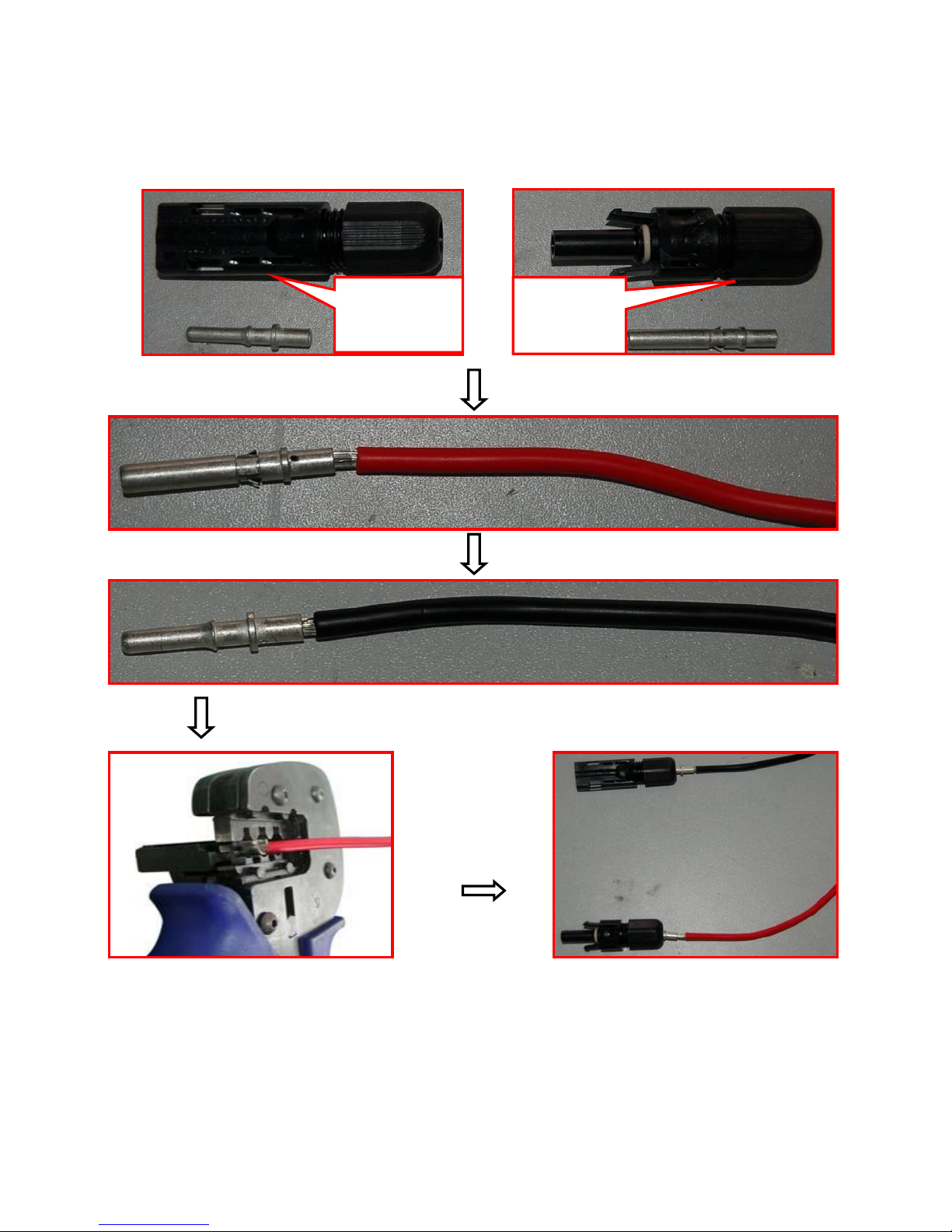
5.4 Connection of the PV generator (DC)
5.4.1 DC input wiring
5.4.2 DC connection Procedure
Step 1: Assemble DC cable to connector at the inverter side. See “5.4.1 DC Input
Wiring”.
Step 2: Disconnect DC and AC circuit breakers.
Negative
terminal
Positive
terminal

<<13
Step 3: Check connection cable of one PV array string for correct polarity and that the
maximum input open circuit voltage does not exceed 450V.
Step 4: Measure DC voltage between positive terminal of the PV string and Earth and
DC voltage between negative terminal of the PV string and Earth. If the two
voltages are constant and not zero, there is an insulation failure somewhere in
this PV string.
Step 5: Plug DC positive and negative connector into corresponding terminals. If it
makes a click sound, it means DC connector has attached to terminals.
5.5 Connecting the inverter to the grid
5.5.1 AC output wiring
Step 1: Unscrew AC output cover at the downside of the machine.

14>>
Step 2: Insert stripped AC cables of appropriate size into the cable glands. Fix the phase
cables into corresponding terminals with screwdriver according to marks. Fix ground
cable into the ground terminal.
Step 3: Screw the AC output cover.
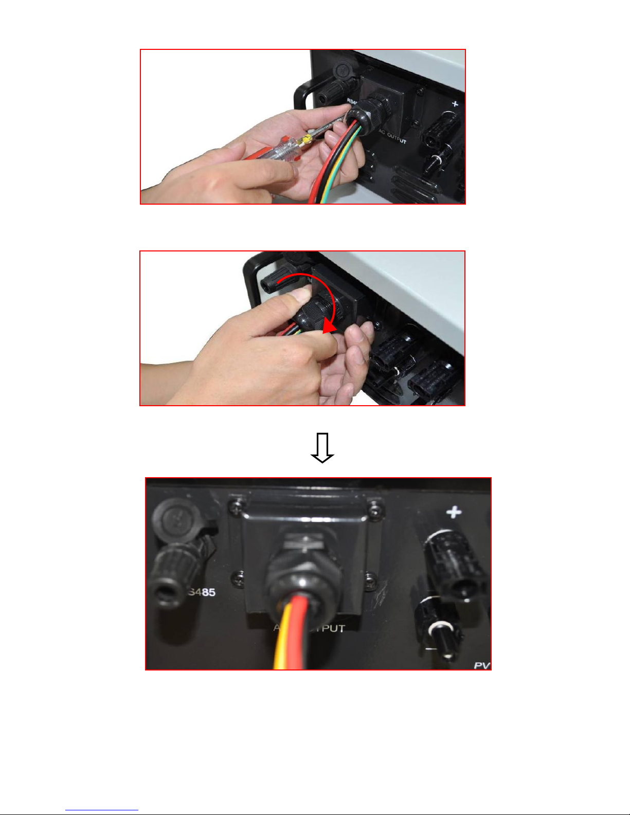
<<15
Step 4: Tighten the cable gland in clockwise direction.

16>>
5.5.2 AC connection Procedure
Step 1: Assembling AC cables to connector supplied. See “5.5.1 AC Output Wring”.
Step 2: Make sure that AC and DC circuit breaker are disconnected.
Step 3: Connect L, N to AC circuit breaker.
−Plug AC connector to corresponding AC terminals.
−Screw AC cables to AC circuit breaker.
Step 4: Connect PE to the ground.
Step 5: Connect AC circuit breaker to utility grid.
Step 6: Make sure that all AC cables are firmly installed.
NOTICE
Assignment of AC cables should be paid attention to, especially
“PE/GND” wire.
5.6 Connecting communication cable
5.6.1 Assembling the RS485 plug connector
Step 1: Make the communication cable through the waterproof ring, and then
connect the cables to the terminal.
1
Blank
2
B
3
A
4
GND
2. Fasten the waterproof ring and case.
3. Finally, match the finished terminal to the RS485 communication port on the inverter’s
case,then it is ready for communication.
<<17
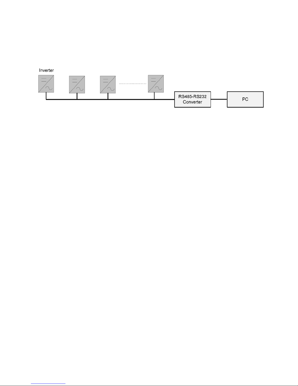
5.6.2 Monitor system connection
The inverter provides RS485 interface to communicate with remote PC. User can
monitor the state of the inverter and observe current running information and history
record via this interface. Below is the method to install the monitoring system.
6. Switch on and off
6.1 Switch on
1. Finish the installation of the PV array, AC grid and the inverter according to the
introduction before.
2. Before switch on, checking whether AC voltage and DC voltage can meet the
requirement of the inverter
3. Switch on the DC breaker at first.
4. Then switch on the AC breaker.
5. When the environment conditions allow the inverter to work, the inverter will
automatically start up and connect the grid to generate power.
6. After the inverter works normally on grid, it can be left working itself without human
control. It can shut down when fault occurs and it can start automatically after the fault is
gone.
6.2 Switch off
1. When solar power was not enough to generate the power, the inverter will shut down
automatically.
2. If you need to shut down the inverter yourself, you can operate the inverter through the
front panel screen.
3. The process of emergency shutdown.
If you need shut down the inverter in emergency, first turn off the AC breaker, then turn
18>>
off the DC breaker, otherwise it may lead to the damage of the DC breaker and danger to
people. If any damage or loss occurs due to not following this requirement, we will not
follow the warranty.
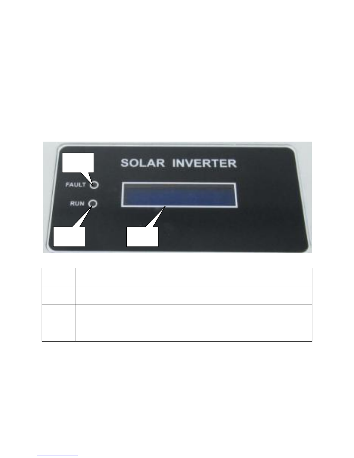
7. Operation
7.1 Display Overview
Object
Descriptions
A
GREEN LED (Working normally)
B
RED LED ( Fault)
C
2 line LCD display
7.2 LED display
The PV inverter is equipped with two LEDS including “green” and “red” which indicate
three different modes of operation.
Green LED: Normal mode
The green LED lighting indicates that the inverter is active and working normally.
B
A
C
This manual suits for next models
1
Table of contents
Other Epcom Inverter manuals


Popular Inverter manuals by other brands

Outback Power Systems
Outback Power Systems GFX1424 installation manual

GW Instek
GW Instek AFG-3022 user manual

Green Gear
Green Gear GE-2000M Operating and maintenance original instructions

Massimo
Massimo MEI 2000 manual

Unipower
Unipower INV2500-HS-60 operating manual

Generac Power Systems
Generac Power Systems QT100 owner's manual


Generac Power Systems
Generac Power Systems 006180-0 owner's manual

YASKAWA
YASKAWA Varispeed f7 Connection manual

LSIS
LSIS H100 troubleshooting manual

Spowdi
Spowdi Mobile Pro manual

Eguana Technologies
Eguana Technologies Evolve 0513U Installation & start?up guide

Motomaster
Motomaster 011-1870-6 instruction manual