1-1. Introduction
This instrument is the Most Versatile Signal Source used as FUNCTION
GENERATOR, SWEEP GENERATOR, PULSE GENERATOR and a FREQUENCY
COUNTER, offering a wide range of applications in both analog and digital electro-
nics such as engineering, manufacturing, servicing, education and hobbyist fields.
VCF(voltage controlled frequency) produces precision sine, square and triangle
waves over the 0.05 Hz to 5 MHz for sub-audible, audio, ultrasonic and RF
applications. A continuously variable DC offset allows the output to be injected
directly into circuits at the correct bias level.
Variable symmetry of the output waveforms converts the instrument to a pulse
generator capable of generating rectangular waves or pulses, ramp or sawtooth
waves and skewed sine waves of variable duty cycle. The sweep generator offers
linear sweep with variable sweep rate and sweep width up to 100:1 frequency
change. The frequency response of any active or passive device up to 5 MHz can
be determined.
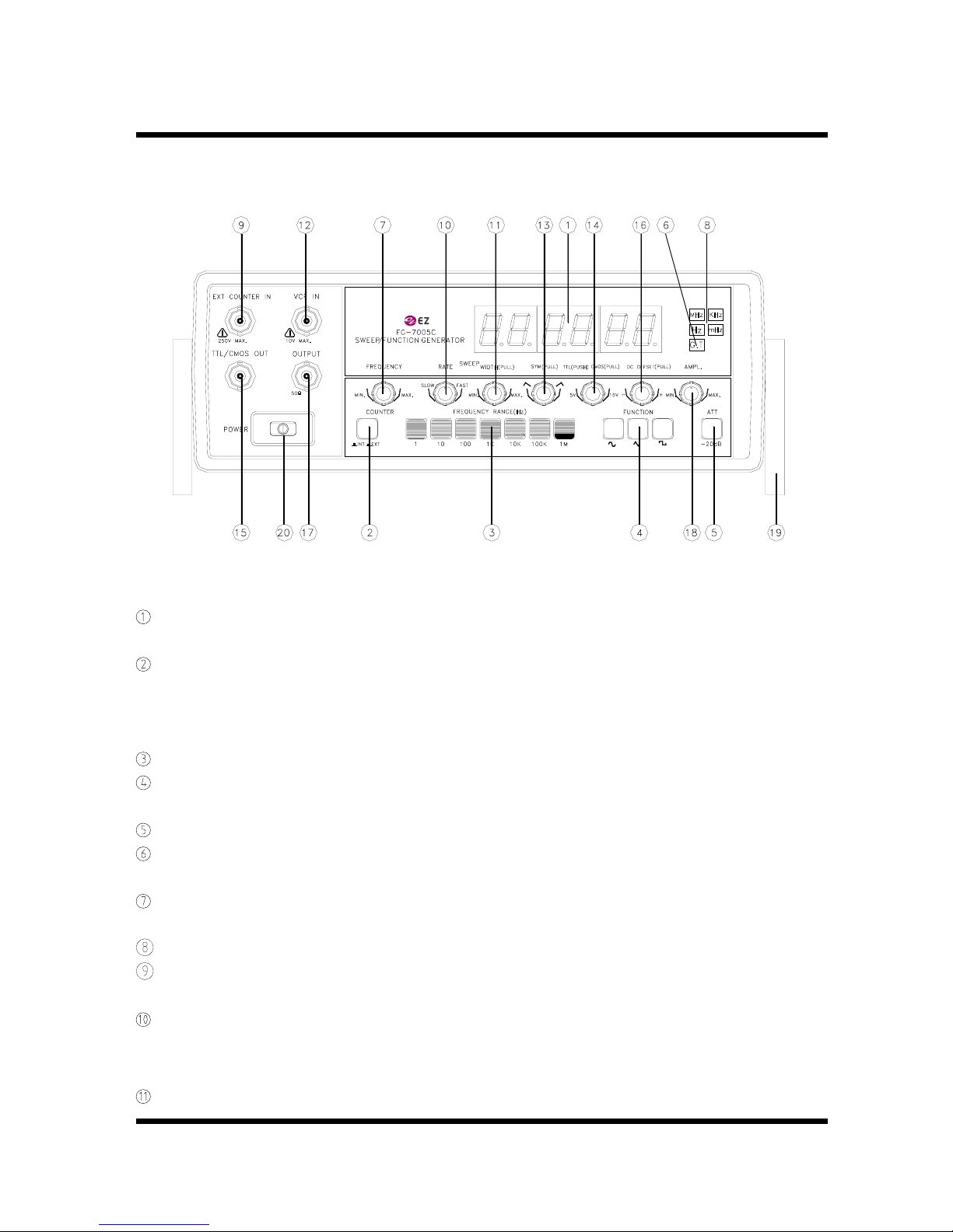
1-2. Technical Specifications
OUTPUT CHARACTERISTICS
Waveforms : Sine, Square, Triangle, Ramp, Pulse, Sawtooth,
TTL/CMOS Leveled Square, DC
Frequency Range : 0.05 Hz to 5 MHz in 7 Range(1,10,100,1K,10K,100K,1M)
Frequency Accuracy : ±5% (1,10,100,1K,10K,100K,1MHz Range ) (Full Scale)
Output Level : 20 Vp-p in open circuit, 10 Vp-p into 50 ΩLoad
Output Impedance : 50 Ω±5%
Attenuator : 20 dB fixed and continuously variable
WAVEFORM CHARACTERISTICS
Sine wave -Flatness : ±2.5V to 5 MHz
-Distortion : Less than 1% at 0.5 Hz to 100 KHz
Square wave -Rise and Fall Time : Less than 25 nS
Triangle wave -Linearity : More than 99% at 0.2 Hz to 100 KHz
TTL Output -Rise and Fall time : Less than 25 nS
-Output Level : TTL Level(H 2.4V, L 0.4V)
CMOS Output -Rise and Fall Time : Less than 150 nS(Max. Out)
(DC – to 2MHz) -Output Level : 4V to 15V ±1V, Variable
DUTY RATIO : 1:1 to 10 : 1