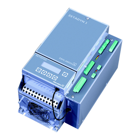
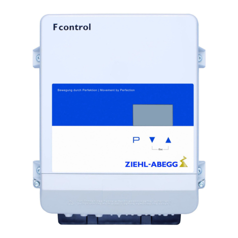
ZIEHL-ABEGG AM-MODBUS-WB User manual

AM-MODBUS-WB
Part.-No. 349077
Bluetooth communication module for frequency inverters from the
Basic series and fans from the ECblue (D+G), AMblue and PMblue
series
Quick Start Guide
Attention, electrostatically sensitive components!
Note chapter mounting the module.
L-BAL-E281-GB 2021/36 Index 004 Part.-No.
english

Content
1 General notes . . . . . . . . . . . . . . . . . . . . . . . . . . . . . . . . . . . . . . . . . . . . 4
1.1 Structure of the short operating instructions . . . . . . . . . . . . . . . . 4
1.2 Exclusion of liability . . . . . . . . . . . . . . . . . . . . . . . . . . . . . . . . . . 4
1.3 Using in Europe . . . . . . . . . . . . . . . . . . . . . . . . . . . . . . . . . . . . . 5
1.4 Using in the USA or Canada . . . . . . . . . . . . . . . . . . . . . . . . . . . 6
1.4.1 FCC Statements for US @ AM-MODBUS-WB, AM-STICK-WB
6
1.4.2 Industry Canada Certification @ AM-MODBUS-WB, AM-
STICK-WB . . . . . . . . . . . . . . . . . . . . . . . . . . . . . . . . . . . 7
1.5 Using in Taiwan . . . . . . . . . . . . . . . . . . . . . . . . . . . . . . . . . . . . . 8
2 Safety instructions . . . . . . . . . . . . . . . . . . . . . . . . . . . . . . . . . . . . . . . . 9
3 General description . . . . . . . . . . . . . . . . . . . . . . . . . . . . . . . . . . . . . . . 9
3.1 Application area . . . . . . . . . . . . . . . . . . . . . . . . . . . . . . . . . . . . . 9
3.2 Function AM-MODBUS-WB . . . . . . . . . . . . . . . . . . . . . . . . . . . . 10
3.3 Transport . . . . . . . . . . . . . . . . . . . . . . . . . . . . . . . . . . . . . . . . . . 11
3.4 Storage . . . . . . . . . . . . . . . . . . . . . . . . . . . . . . . . . . . . . . . . . . . . 11
3.5 Disposal / recycling . . . . . . . . . . . . . . . . . . . . . . . . . . . . . . . . . . 11
4 Mounting the module . . . . . . . . . . . . . . . . . . . . . . . . . . . . . . . . . . . . . . 11
5 Installation . . . . . . . . . . . . . . . . . . . . . . . . . . . . . . . . . . . . . . . . . . . . . . 13
5.1 Safety precautions . . . . . . . . . . . . . . . . . . . . . . . . . . . . . . . . . . . 13
5.2 Connection terminal type A-G-247NW for service . . . . . . . . . . . 13
5.3 RS-485 interface for MODBUS . . . . . . . . . . . . . . . . . . . . . . . . . . 14
5.3.1 Automatic addressing . . . . . . . . . . . . . . . . . . . . . . . . . . . 15
6 Operating by terminal . . . . . . . . . . . . . . . . . . . . . . . . . . . . . . . . . . . . . 17
6.1 Menu operation . . . . . . . . . . . . . . . . . . . . . . . . . . . . . . . . . . . . . 17
6.2 Menu structure . . . . . . . . . . . . . . . . . . . . . . . . . . . . . . . . . . . . . . 18
7 Bluetooth® for wireless communication . . . . . . . . . . . . . . . . . . . . . . 19
7.1 AM-MODBUS-WB with Bluetooth version 4.0 . . . . . . . . . . . . . . . 19
7.2 Establishing the Bluetooth connection . . . . . . . . . . . . . . . . . . . . 20
8 Diagnostic . . . . . . . . . . . . . . . . . . . . . . . . . . . . . . . . . . . . . . . . . . . . . . . 26
8.1 Status LEDs on the module . . . . . . . . . . . . . . . . . . . . . . . . . . . . 26
Quick Start Guide AM-MODBUS-WB
L-BAL-E281-GB 2021/36 Index 004 Part.-No.
2/28

9 Enclosure . . . . . . . . . . . . . . . . . . . . . . . . . . . . . . . . . . . . . . . . . . . . . . . 27
9.1 Connection diagram . . . . . . . . . . . . . . . . . . . . . . . . . . . . . . . . . . 27
9.2 Manufacturer reference . . . . . . . . . . . . . . . . . . . . . . . . . . . . . . . 28
9.3 Service information . . . . . . . . . . . . . . . . . . . . . . . . . . . . . . . . . . . 28
Quick Start Guide AM-MODBUS-WB
L-BAL-E281-GB 2021/36 Index 004 Part.-No.
3/28

1 General notes
Compliance with the following instructions is mandatory to ensure the functionality and
safety of the product. If the following instructions given especially but not limited for
general safety, transport, storage, mounting, operating conditions, start-up, mainte-
nance, repair, cleaning and disposal / recycling are not observed, the product may not
operate safely and may cause a hazard to the life and limb of users and third parties.
Deviations from the following requirements may therefore lead both to the loss of the
statutory material defect liability rights and to the liability of the buyer for the product that
has become unsafe due to the deviation from the specifications.
1.1 Structure of the short operating instructions
This Quick Start Guide contains basic information about safety, use, installation and
quick start-up and is only valid in connection with the assembly instructions or operating
instructions of the device in which this module is installed.
The remarks concerning safety, installation and connection described there must be
followed!
1.2 Exclusion of liability
Concurrence between the contents of these operating instructions and the described
hardware and software in the device has been examined. It is still possible that non-
compliances exist; no guarantee is assumed for complete conformity. To allow for future
developments, construction methods and technical data given are subject to alteration.
We do not accept any liability for possible errors or omissions in the information con-
tained in data, illustrations or drawings provided.
ZIEHL-ABEGG SE is not liable for damage due to misuse, incorrect use, improper use
or as a consequence of unauthorized repairs or modifications.
Quick Start Guide AM-MODBUS-WB General notes
L-BAL-E281-GB 2021/36 Index 004 Part.-No.
4/28

1.3 Using in Europe
The module comply with the Radio Equipment Directive (RED) 2014/53/EU.
•Article 3.1[a]: Protection of health and safety of persons and of domestic animals
–ETSI EN 300 328 V2.1.1
–EN 301 489-1 V2.1.1 (2017-02)
–EN 60950-1:2006 + A11:2009 + A1:2010 + A12:2011 + AC:2011 + A2:2013
•Article 3.1[b]: Adequate level of electromagnetic compatibility
–EN 301 489-17 V2.2.1:2012-09
•Article 3.2: Effective and efficient use of radio spectrum
–EN 300 328 V2.1.1:2016-11
The CE symbol confirms compliance with the directive.
The final product, in which the module and the fan or frequency inverter is installed, must
meet the requirements of 2014/53 / EU.
The modules may be used in the following countries:
Austria, Belgium, Cyprus, Czech Republic, Denmark, Estonia, Finland, France, Ger-
many, Greece, Hungary, Ireland, Italy, Latvia, Lithuania, Luxembourg, Malta, Poland,
Portugal, Slovakia, Slovenia, Spain, Sweden, the Netherlands, the United Kingdom,
Switzerland and Norway
Quick Start Guide AM-MODBUS-WB General notes
L-BAL-E281-GB 2021/36 Index 004 Part.-No.
5/28

1.4 Using in the USA or Canada
Information
The following information is intended for using the product in the USA or Canada and is
therefore not taken into consideration in translations.
1.4.1 FCC Statements for US @ AM-MODBUS-WB, AM-STICK-WB
FCC Notice
This device contains FCC ID: T7V1740 (PAN1740), including the antennas, which are
listed below, complies with Part 15 of the FCC Rules.
The device meets the requirements for modular transmitter approval as detailed in FCC
public Notice DA00-1407 transmitter.
Operation is subject to the following two conditions
1. this device may not cause harmful interference
2. this device must accept any interference received, including interference that may
cause undesired operation
Caution
The FCC requires the user to be notified that any changes or modifications made to this
device that are not expressly approved by ZIEHL-ABEGG SE may void the user's
authority to operate the equipment.
Changes or modifications not expressly approved by the party responsible for compli-
ance could void the user's authority to operate the equipment.
This equipment has been tested and found to comply with the limits for a Class B digital
device, pursuant to Part 15 of the FCC Rules. These limits are designed to provide
reasonable protection against harmful interference in a residential installation. This
equipment generates uses and can radiate radio frequency energy and, if not installed
and used in accordance with the instructions, may cause harmful interference to radio
communications. However, there is no guarantee that interference will not occur in a
particular installation.
If this equipment does cause harmful interference to radio or television reception, which
can be determined by turning the equipment off and on, the user is encouraged to try to
correct the interference by one or more of the following measures:
•Reorient or relocate the receiving antenna.
•Increase the separation between the equipment and receiver.
•Connect the equipment into an outlet on a circuit different from that to which the
receiver is connected.
•Consult the dealer or an experienced radio/TV technician for help
Labeling Requirements
The Original Equipment Manufacturer (OEM) must ensure that FCC labelling require-
ments are met. This includes a clearly visible label on the outside of the OEM enclosure
specifying the appropriate Panasonic FCC identifier for this product as well as the FCC
Quick Start Guide AM-MODBUS-WB General notes
L-BAL-E281-GB 2021/36 Index 004 Part.-No.
6/28

Notice above. The FCC identifier is FCC ID: T7V1740. This FCC identifier is valid for all
PAN1740 modules.
In any case the end product must be labelled exterior with "Contains FCC ID: T7V1740"
Antenna Warning
For the related part number of PAN1740.
This device is tested with a standard SMA connector and with the antennas listed below.
When integrated in the OEMs product, these fixed antennas require installation prevent-
ing end-users from replacing them with non-approved antennas. Any antenna not in the
following table must be tested to comply with FCC Section 15.203 for unique antenna
connectors and Section 15.247 for emissions.
Item Part Number Manufacturer Frequency Band Type Gain (dBi)
1 LDA212G3110K Murata 2.4 GHz Chip-Antenna +0.9
RF Exposure
The radiated output power of PAN1740 with mounted ceramic antenna (FCC ID:
T7V1740) is far below the FCC radio frequency exposure limits.
Nevertheless, the PAN1740 shall be used in such a manner that the potential for human
contact during normal operation is minimized
1.4.2 Industry Canada Certification @ AM-MODBUS-WB, AM-STICK-WB
This device contains "Contains IC: 216Q-1740".
PAN1740 is licensed to meet the regulatory requirements of Industry Canada (IC),
license: IC: 216Q-1740.
Manufacturers of mobile, fixed or portable devices incorporating this module are advised
to clarify any regulatory questions and ensure compliance for SAR and/or RF exposure
limits. Users can obtain Canadian information on RF exposure and compliance from
www.ic.gc.ca.
This device has been designed to operate with the antennas listed in the Table above,
having a maximum gain of 0.9 dBi. Antennas not included in this list or having a gain
greater than 0.9 dBi are strictly prohibited for use with this device. The required antenna
impedance is 50 ohms. The antenna used for this transmitter must not be co-located or
operating in conjunction with any other antenna or transmitter.
Due to the model size the IC identifier is displayed in the installation instruction only and
can not be displayed on the modules label due to the limited size (8.7x15.6mm).
IC Notice
The devices contains "Contains IC: 216Q-1740", including the antennas, which are listed
in above, complies with Canada RSS-GEN Rules. The device meets the requirements
for modular transmitter approval as detailed in RSS-GEN.
Operation is subject to the following two conditions:
1. This device may not cause harmful interference
2. This device must accept any interference received, including interference that may
cause undesired operation
Quick Start Guide AM-MODBUS-WB General notes
L-BAL-E281-GB 2021/36 Index 004 Part.-No.
7/28

Le présent appareil est conforme aux CNR d'Industrie Canada applicables aux appareils
radio exempts de licence.
L'exploitation est autorisée aux deux conditions suivantes :
1. l'appareil ne doit pas produire de brouillage, et
2. l'utilisateur de l'appareil doit accepter tout brouillage radioélectrique subi, même si
le brouillage est susceptible d'en compromettre le fonctionnement.
PAN1740 est garanti conforme aux dispositions règlementaires d’Industry Canada (IC),
licences: IC: 216Q-1740 Il est recommandé aux fabricants d’appareils fixes, mobiles ou
portables de consulter la réglementation en vigueur et de vérifier la conformité de leurs
produits relativement aux limites d’exposition aux rayonnements radiofréquence ainsi
qu’au débit d’absorption spécifique maximum autorisé
Des informations pour les utilisateurs sur la réglementation Canadienne concernant
l’exposition aux rayonnements RF sont disponibles sur le site www.ic.gc.ca.
Ce produit a été développé pour fonctionner spécifiquement avec les antennes listées
dans le tableau ci-dessus, présentant un gain maximum de 0.9dBi. Des antennes autres
que celles listées ici, ou présentant un gain supérieur a 0.9dBi ne doivent en aucune
circonstance être utilises en combinaison avec ce produit. L’impédance des antennes
compatibles est 50Ohm. L’antenne utilisée avec ce produit ne doit ni être située à
proximité d’une autre antenne ou d’un autre émetteur, ni être utilisée conjointement avec
une autre antenne ou un autre émetteur. En raison de la taille du produit, l’identifiant IC
est fourni dans le manuel d’installation.
Labeling Requirements
The Original Equipment Manufacturer (OEM) must ensure that IC labelling requirements
are met. This includes a clearly visible label on the outside of the OEM enclosure
specifying the appropriate Panasonic IC identifier for this product as well as the IC Notice
above. The IC identifier is 216Q-1740. This IC identifier is valid for all PAN1740 modules.
In any case the end product must be labelled exterior with "Contains IC: 216Q-1740"
Obligations d’étiquetage
Les fabricants d’équipements (OEM) doivent s’assurer que les obligations d’étiquetage
du produit final sont remplies. Ces obligations incluent une étiquette clairement visible à
l’extérieur de l’emballage externe, comportant l’identifiant IC du module Panasonic
inclus, ainsi que la notification ci-dessus.
Les identifiants IC sont: IC: 216Q-1740
Ces identifiants sont valides pour tous les modules PAN1740. Dans tous les cas les
produits finaux doivent indiquer sur leur emballage externe une des mentions suivantes:
"Contient IC: 216Q-1740"
1.5 Using in Taiwan
The module is NCC approved for use in Taiwan. It meets the requirements of the Low-
Power-Radio-Frequency Devices Technology Regulations as detailed in NCC LP0002
(2020) Section 4.10.1. Test report for AM-MODBUS-WB see CN21RFOW.
NCC approval mark and identification number for AM-MODBUS-WB
Quick Start Guide AM-MODBUS-WB General notes
L-BAL-E281-GB 2021/36 Index 004 Part.-No.
8/28

2 Safety instructions
Information
Mounting, electrical connection, and start-up operation may only be carried out by an
electrical specialist in accordance with electrotechnical regulations (e.g. EN 50110 or
EN 60204)!
Danger due to electric current
•It is generally forbidden to carry out work on electrical live parts. Protection class of the
device when open is IP00! It is possible to touch hazardous voltages directly.
•The 5 electrical safety rules must be observed!
•The safe isolation from the supply must be checked using a two-pole voltage
detector.
•Even after disconnecting the mains voltage, life-threatening charges can appear
between the protective ground “PE” and the mains connection.
Waiting period at least 3 minutes!
•Opening the device in which the module is to be installed (fan, inverter) is only
allowed when the mains power is switched off and after waiting at least three minutes.
•Through use of capacitors, danger of death exists even after switching off the device
through directly touching the energized parts or due to parts that have become
energized due to faults.
3 General description
3.1 Application area
Communication module for frequency inverters from the Basic series and fans from the
ECblue (D+G), AMblue and PMblue series.
Information
The AM-MODBUS(-W)(-WB) module is intended exclusively for integration and utilisa-
tion in host devices (fans and converters) with "Add-on" module function from
ZIEHL-ABEGG.
Quick Start Guide AM-MODBUS-WB Safety instructions
L-BAL-E281-GB 2021/36 Index 004 Part.-No.
9/28

Attention!
The module, and therefore also the end device in which it is installed (fan/frequency
inverter), is not designed for use in life-sustaining devices or systems where a
malfunction can lead to serious personal injury.
It is not permissible to use the module, or the end device in which it is installed, as a
critical component if the failure or malfunction of the component can impair the safety or
functionality of life-sustaining devices.
Customers who sell or use these ZIEHL-ABEGG products for these applications do so at
their own risk. They undertake to reimburse ZIEHL-ABEGG in full for any possible costs
that may occur.
Those customers also agree to assign a new and secure access code during the
installation of the module device (AM-MODBUS-W, -WB). They are required to disclose
the access code to their customers.
3.2 Function AM-MODBUS-WB
Bluetooth interface
The module features a Bluetooth (Low Energy) interface for wireless communication
with a smartphone or tablet. The "ZAset mobile" app developed by ZIEHL-ABEGG
enables easy programming and diagnosis of the end device which hosts this module.
The app can be downloaded from Google Play Store or iTunes.
RS-485 interface
The RS-485 interface for MODBUS RTU allows access to the MODBUS registers and
also enables menu-guided programming with the A-G-247NW manual terminal.
Devices with integrated auxiliary module AM-MODBUS-WB offer the following
functions:
•The ECblue fan and the frequency inverter can be communicated with via the module.
To program desired functions during start-up or for diagnostics, the module can be
inserted fort he required period of time or can be left in the device.
•Devices can be integrated into existing MODBUS-RTU networks. A MODBUS net-
work with several members can be built up, communication is made via MODBUS-
RTU.
•The members connected in a network can be addressed automatically. Manual
addressing is not necessary!
•Parameter sets can be saved by the module in the terminal type A-G-247NW and
transferred to other devices (
Operating Instructions Terminal Type A-G-247NW).
•It is possible to save and exchange parameters sets by PC via the USB interface of
the terminal type A-G-247NW (
Operating Instructions terminal type A-G-247NW).
•For ECblue fans tacho output with frequency signal, the evaluation of the signal
shows the current fan speed.
Quick Start Guide AM-MODBUS-WB General description
L-BAL-E281-GB 2021/36 Index 004 Part.-No.
10/28

3.3 Transport
•The device is packed ex factory to suit the transport method previously agreed.
•The device may only be transported in the original packaging.
•Avoid shocks and impacts to the device during the transport.
•During manual handling the human lifting and carrying restrictions must be observed
and adhered to.
3.4 Storage
•The device must be stored in its original packaging in a dry and weather-proof room.
•Avoid exposure to extreme heat and cold.
•Avoid over-long storage periods (we recommend a maximum of one year).
3.5 Disposal / recycling
Disposal must be carried out professionally and in an environmentally friendly way in
accordance with the respective national legal stipulations.
"Separate the materials by type and in an environmentally friendly way.
"If necessary, commission a specialist company with the waste disposal.
4 Mounting the module
Danger due to electric current
•Always read the safety instructions chapter before mounting!
•The terminating device (fan, converter) in which the module is to be installed must
be disconnected from the line voltage for at least 3 minutes before opening!
Attention, electrostatic sensitive devices!
•Damage to electronic components by electrostatic charging must be prevented!
•Touch the protective earth connection in the terminal to equalize the potential
immediately before removing the module from the packing. This applies regardless
of whether the device is already connected to the line.
•Equalize the potential again shortly before installation if the module is not installed
immediately after unpacking.
•After unpacking the module, check for possible transport damage and insert it in the
slot provided. Do not touch the connection!
Quick Start Guide AM-MODBUS-WB Mounting the module
L-BAL-E281-GB 2021/36 Index 004 Part.-No.
11/28

Proceed as follows:
"ECblue: Mount the module in the housing with the two enclosed screws (permissible
tightening torque M
A
1.3 Nm).
"Fcontrol Basic, Icontrol Basic, PMcontrol, PMIcontrol (AMblue/PMblue): Press the
module into the retaining clips.
"Permissible tightening torque of connection terminals M
A
0.24 Nm.
"When an AM-MODBUS-W/WB module is installed in a fan or converter from
ZIEHL-ABEGG, the enclosed label must be stuck to the housing of the terminating
device.
–"FCC/IC" label for AM-MODBUS-W
–"FCC/IC" label for AM-MODBUS-WB
Example for mounting the add-on module
Example: Sticking the "FCC/IC" label
“AM-MODBUS-W” onto a fan housing.
Quick Start Guide AM-MODBUS-WB Mounting the module
L-BAL-E281-GB 2021/36 Index 004 Part.-No.
12/28

5 Installation
5.1 Safety precautions
Danger due to electric current
•Work on electric components may only be carried out by trained electricians or by
persons instructed in electricity under the supervision of an electrician in accordance
with electrical engineering regulations.
•It is forbidden to carry out work on electrically live parts.
5.2 Connection terminal type A-G-247NW for service
If necessary an external terminal can be connected. This can be e.g. necessary to adapt
the pre-setting during start-up.
The connection is made at the terminals: A (D+), B (D-) and GND. E. g. by a 4-wire
telephone cable type: J-Y (St) Y 2x2x0.6 (or similar), maximum cable length
approx.250 m.
AM-MODBUS
B
(D-) GND A
(D+)
B
(D-) fout GNDGND A
(D+)
A-G-247NW
+ 3,3 V
IRDA-RXD
IRDA-TXD
IRDA-SD
A
(D+)
B
(D-)
GND
+ 5 V
13.12.2018
v_modbus_link_terminal.vsd
ID1 ID2
The voltage supply of the terminal is made by the accumulators inserted there or the
plug power supply unit.
Quick Start Guide AM-MODBUS-WB Installation
L-BAL-E281-GB 2021/36 Index 004 Part.-No.
13/28

5.3 RS-485 interface for MODBUS
The device comes equipped with a RS-485 interface for networking via MODBUS.
Conntection at: “A (D+)”, “B (D-)” and “GND”.
11.03.2014
v_am_modbus_connect.vsd
ID1 GND A
(D+)
B
(D-) ID2GND A
(D+)
B
(D-)
B
(D-) ID1 GND A
(D+)
B
(D-) ID2GND A
(D+)
MODBUS
(RS-485)
MODBUS
(RS-485)
Addressing
Addressing
MODBUS
(RS-485)
MODBUS
(RS-485)
Addressing
Addressing
The connections for MODBUS “A (D+)”, “B (D-)” and “GND” are available double on the module and
are connected with each other internally.
Information
•You must ensure correct connection; i.e. “A (D+)” must also be connected on the
following devices to “A (D+)”. The same applies to “B (D-)”.
•In addition, a "GND" connection must be established, as dissimilar potential (over 10
V!) will lead to the destruction of the RS-485 interface (e.g. lightning).
•Except the data link “A (D+)”, “B (D-)” and “GND” (for automatic addressing additional
“ID1” - “ID2” see following chapter) no further cable cores of the data line may be used.
•Pay attention to sufficient distance from powerlines and motor wires (min. 20 cm).
•A maximum of 64 participants can be directly connected to one another, and a further
63 participants via a repeater. To support automatic addressing the repeater type Z-G-
1NE is available.
Example for MODBUS connection
MODBUS
26.02.2007
v_modbus_verbindung.vsd
The data line must be conducted from one device
to the next. No other type of wiring is allowed!
Always use only two wires of one lead (twisted
pair) for the connection.
Recommended wire types
1. CAT5 / CAT7 cables
2. J-Y (St) 2x2x0.6 (telephone cable)
3. AWG22 (2x2 twisted pair)
Max allowed wire length 1000 m (CAT5/7 500 m).
Shielding
The use of shielded cables is normally not needed but offers high protection against
electromagnetic interferences, especially high frequencies. However, the effectiveness
of the shield depends on careful installation of the line.
Quick Start Guide AM-MODBUS-WB Installation
L-BAL-E281-GB 2021/36 Index 004 Part.-No.
14/28

If shielded cables are used, the shield should be placed at “PE” on at least one side
(preferably on the master connection). The occurrence of compensating currents may
have to be considered if the shield is contacted on both sides.
Shield connection correct Shield connection incorrect
When using telephone cable with four cable cores, we recommend the following
allocation:
•A (D+) red
•B (D-) black
•ID1 - ID2 yellow (for automatic addressing)
•GND white
Default interface parameter
•Baudrate 19200
•Bits 8
•Parity Even
•Stop bits 1
•Handshake none
Information
•Addressing is performed depending on version by display, an external terminal or a
PC with the appropriate software (automatic addressing following chapter).
•The MODBUS register description and the information sheet “Network structure of
MODBUS” can be requested from our Support Department V-STE for control systems
- ventilation.
5.3.1 Automatic addressing
Automatic addressing can be started when the connections “ID1” and “ID2” for “Address-
ing” are connected with each other additionally next to the bus connection. I. e. it is no
longer necessary to address every user manually in the network.
Quick Start Guide AM-MODBUS-WB Installation
L-BAL-E281-GB 2021/36 Index 004 Part.-No.
15/28

The connection at the terminal is made at the terminals: A (D+), B (D-) and GND.
Connection of the users via the terminals: A (D+), B (D-), GND and ID1 / ID2
Information
•Except the data link “A (D+)”, “B (D-)” the “ID1 - ID2” and the “GND” connection may no
further cable cores of the data line be used.
•The connections for the automatic addressing “ID1” and “ID2” are not directly
connected electrically with each other. These may not be bridged; any order of
connection is possible.
•If a repeater is necessary and automatic addressing should be carried out, only the
repeater of the Z-G-1NE type can be used, only it can relay the addressing signal.
•Maximum number of members in automatic addressing:
–With hand held terminal type A-G-247 and control unit NETcon type CXG-327ANE
max. 63 members.
–With control module UNIcon MODBUS Master max. 32 members.
On the first user that is connected directly to a terminal, MODBUS Master or PC, “GND”
and “ID1” or “ID2” must be bridged. This is recognised as a result and occupied by
address 1.
For the following users the connection “ID1” or “ID2” of a user respectively is connected
with connection “ID1” or “ID2” of the next user.
The automatic addressing of other users is initiated by the previous user via this
connection.
If you have any questions about automatic addressing, please contact our support
(see service information).
Quick Start Guide AM-MODBUS-WB Installation
L-BAL-E281-GB 2021/36 Index 004 Part.-No.
16/28

6 Operating by terminal
6.1 Menu operation
"Switch over between actual value* and “Start” with
|
Esc
|
arrow key.
"Switch over between “Start” and actual value* with
|
i
|
key.
* Actual value depending on device type: "Speed" / rpm, "Frequency" / Hz, "Modulation" / %
"By pushing the P- key one reaches the menu item “Start”.
"Return to the menu group “Start” using arrow key
|
Esc
|
.
P↓
▲ ▼"One moves up and down within the menu group using the arrow keys.
Display for english menu language “GB ”
Quick Start Guide AM-MODBUS-WB Operating by terminal
L-BAL-E281-GB 2021/36 Index 004 Part.-No.
17/28

6.2 Menu structure
PIN 0010
STOP
← ← ← ← User Service → → →
→
▲
▼
▲
▼
▲
▼
▲
▼
↑
|
Esc
|
P
↓
↑
|
Esc
|
P
↓
↑
|
Esc
|
P
↓
↑
|
Esc
|
P
↓
↑
|
Esc
|
P
↓
▲ ▼ ▲ ▼ ▲ ▼ ▲ ▼
Display for english menu language “GB ”
Selection of the menu group (e.g. “Setting”) to the right through the ▼-key, to the left through the ▲-key.
You can go to the menu items in the menu groups (e.g. “Set Intern1”) by using the P-key. Use the arrow
keys to move up and down within the menu group.
The menu groups consist of one area for the user (user menu) and one area for installation (service). The
service area can be protected against unauthorized access by using a PIN.
To make adjustments, press the P-key after selecting the menu item. If the previously set value starts to
flash, it can be adjusted with the ▼ + ▲ keys and then saved with the P-key. To exit the menu without
making any changes, use the “Esc” key, i.e., the originally set values remain.
Information
The other settings depend on the type of device in which the module is installed see
Operating Instructions.
Quick Start Guide AM-MODBUS-WB Operating by terminal
L-BAL-E281-GB 2021/36 Index 004 Part.-No.
18/28

7 Bluetooth® for wireless communication
7.1 AM-MODBUS-WB with Bluetooth version 4.0
The AM-MODBUS-WB includes a Bluetooth LE (BLE) module that enables the user to
take advantage of the 4.0+ Bluetooth technology with an Android device, iPhone, iPad or
laptop.
BLE stands for Bluetooth Low Energy or Bluetooth Smart as of Bluetooth version 4.0.
In a hard-wired system, wireless communication is primarily designed in order to have
a second interface for communicating with the device (e.g., for configuration and diag-
nostics).
ZIEHL-ABEGG provides the "ZAset mobile" app for the use of mobile devices via Blue-
tooth Low Energy. The app requires Android devices from version 4.3 onwards and iOS
devices from version 8. onwards. The app can be downloaded from Google Play Store
or iTunes.
The wireless communication uses the MODBUS protocol (MODBUS-TCP). The Blue-
tooth addressing takes place via the Bluetooth address.
The Bluetooth scan automatically detects all devices within range. The app can then
connect with these devices via the Bluetooth address.
The MODBUS address has no significance for Bluetooth communication, but it is still
read and displayed during a Bluetooth scan. This means that you can also identify the
device via its MODBUS address if one has been assigned. Therefore, it is a good idea to
assign a MODBUS address even if the MODBUS network is not in use.
You can change the MODBUS address via the app in the device "IO Setup"; see the
"Bus Address" parameter. Then apply the same procedure to the next device.
Access code (0–9999)
Unlike in the case of RS-485 communication, you can protect your device with an access
code (0 - 9999) for wireless communication via the AM-MODBUS-WB.
During installation, you must assign a separate and secure access code to every Blue-
tooth device or group of Bluetooth devices.
The factory setting is
|
9999
|
. An access code with the value
|
0
|
deactivates the access
protection function.
"If the access code is deactivated, the app prompts you to turn it on.
"If the access code is set to the factory setting, the app will prompt you to change it.
Information
You must switch off or reset the device to activate the access code after changing it
manually. You can change the access code via the app in the device "Controller Setup";
see the Network Key parameter.
Quick Start Guide AM-MODBUS-WB Bluetooth® for wireless communication
L-BAL-E281-GB 2021/36 Index 004 Part.-No.
19/28

Technical data for wireless communication
Frequency 2.4 GHz
Communications range Approx. 10 m in rooms, up to 30 m in the free field, generally
depends strongly on external influences and the installation sit-
uation.
For ECblue fans with aluminum controller housing cover, the
communication range is reduced by at least 50 %.
7.2 Establishing the Bluetooth connection
Proceed as follows:
"Depending on your device, download and install the "ZAset mobile" app from Google
Play Store or Apple App Store.
"Switch on the line voltage to the fan/frequency converter in compliance with the safety
instructions.
"Activate the Bluetooth connection on the mobile device (smartphone). Additionally
allow location determination in Android.
"Start the app.
Icon of the app Intro
Quick Start Guide AM-MODBUS-WB Bluetooth® for wireless communication
L-BAL-E281-GB 2021/36 Index 004 Part.-No.
20/28
This manual suits for next models
1
Table of contents
Other ZIEHL-ABEGG Inverter manuals
Popular Inverter manuals by other brands

Mitsubishi Electric
Mitsubishi Electric 700 Series instruction manual

Streetwize
Streetwize SWPSI2000 INFORMATION FOR USE

SMA
SMA SUNNY ISLAND 4.4M Replacement of Various Components

Gree
Gree GMV-Pdhm280W/Na-M Installation and operating instruction manual

SolarEdge
SolarEdge SE3000H-US installation guide

Hitachi
Hitachi RPIL-1.0PNN1DH Service manual