Icel Manaus GV-2005 User manual

EconomicalType1‐channel
ArbitraryWaveformGenerator
UserManual
GV‐2005


GeneralWarranty
ICELMANAUSwarrantsthattheproductwillbefreefromdefectsinmaterialsand
workmanshipforaperiodof3years(1yearforaccessories)fromthedateofpurchaseof
theproductbytheoriginalpurchaserfromtheICELMANAUSCompany.Thiswarranty
onlyappliestotheoriginalpurchaserandisnottransferabletothethirdparty.Ifthe
productprovesdefectiveduringthewarrantyperiod,ICELMANAUSeitherwillrepairthe
defectiveproductwithoutchargeforpartsandlabor,orwillprovideareplacementin
exchangeforthedefectiveproduct.Parts,modulesandreplacementproductsusedby
ICELMANAUSforwarrantyworkmaybeneworreconditionedlikenewperformance.All
replacedparts,modulesandproductsbecomethepropertyofICELMANAUS.
Inordertoobtainserviceunderthiswarranty,CustomermustnotifyICELMANAUSofthe
defectbeforetheexpirationofthewarrantyperiod.Customershallberesponsiblefor
packagingandshippingthedefectiveproducttotheservicecenterdesignatedbyICEL
MANAUS,andwithacopyofcustomerproofofpurchase.
Thiswarrantyshallnotapplytoanydefect,failureordamagecausedbyimproperuseor
improperorinadequatemaintenanceandcare.ICELMANAUSshallnotbeobligatedto
furnishserviceunderthiswarrantya)torepairdamageresultingfromattemptsby
personnelotherthanICELMANAUSrepresentativestoinstall,repairorservicethe
product;b)torepairdamageresultingfromimproperuseorconnectiontoincompatible
equipment;c)torepairanydamageormalfunctioncausedbytheuseofnon‐ICEL
MANAUSsupplies;ord)toserviceaproductthathasbeenmodifiedorintegratedwith
otherproductswhentheeffectofsuchmodificationorintegrationincreasesthetimeor
difficultyofservicingtheproduct.
PleasecontactthenearestICELMANAUS'sSalesandServiceOfficesforservicesora
completecopyofthewarrantystatement.
Forbetterafter‐salesservice,pleasevisitwww.ICEL‐ MANAUS.com.brandregister
thepurchasedproductonline.
Exceptingtheafter‐salesservicesprovidedinthissummaryortheapplicablewarrantystatements,
ICELMANAUSwillnotofferanyguaranteeformaintenancedefinitelydeclaredorhinted,including
butnotlimitedtotheimpliedguaranteeformarketabilityandspecial‐purposeacceptability.ICEL
MANAUSshouldnottakeanyresponsibilitiesforanyindirect,specialorconsequentdamages.

i
TableofContents
1.GeneralSafety Requirements......................................................................................1
2.Safety Terms and Symbols...........................................................................................2
3.General Characteristics...............................................................................................3
4.Quick Start..................................................................................................................4
Front/RearPanelandUserInterface......................................................................................5
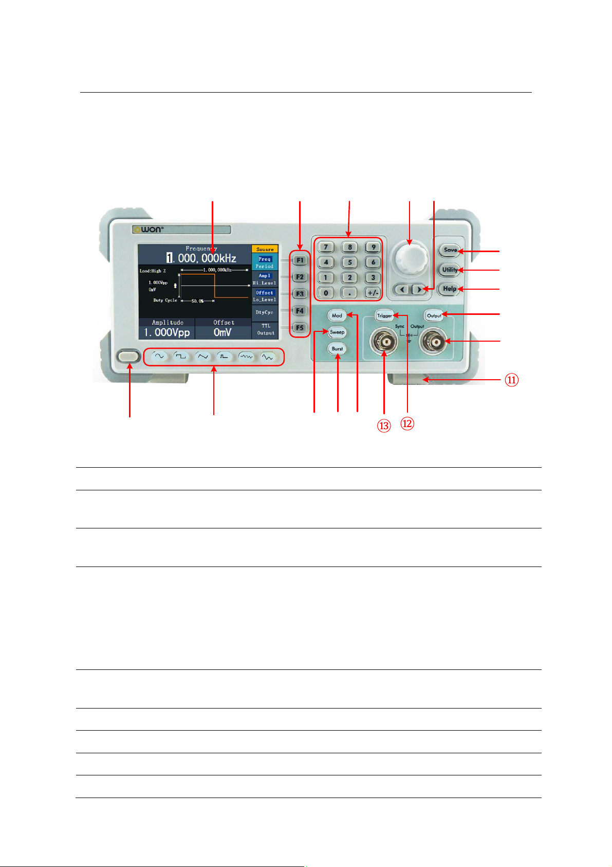
FrontPanelOverview...............................................................................................................................5
RearPanelOverview................................................................................................................................6
UserInterface...........................................................................................................................................7
GeneralInspection.................................................................................................................8
FootStoolAdjustment...........................................................................................................8
Power‐OnCheck....................................................................................................................9
ACPowerInputSetting............................................................................................................................9
PowerOn..................................................................................................................................................9
5.Front Panel Operation..............................................................................................10
ChannelOutputOn/Off.......................................................................................................11
Tosetsignals.......................................................................................................................11
ToOutputSineSignals............................................................................................................................11
ToSettheFrequency/Period...............................................................................................................................11
ToSettheAmplitude...........................................................................................................................................12
ToSettheOffset..................................................................................................................................................12
ToSettheHighLevel............................................................................................................................................12
ToSettheLowLevel............................................................................................................................................12
ToOutputSquareSignals.......................................................................................................................12
ToSettheDutyCycle...........................................................................................................................................13
ToOutputRampSignals.........................................................................................................................14
ToSettheSymmetry............................................................................................................................................15
ToOutputPulseSignals..........................................................................................................................15
ToSetthePulseWidth/DutyCycle....................................................................................................................16
ToOutputNoiseSignals.........................................................................................................................17
ToOutputArbitrarySignals....................................................................................................................17
ToSelecttheBuilt‐inWaveform...........................................................................................................................18
TheUser‐DefinableWaveform.............................................................................................................................20
ToOutputDC..........................................................................................................................................21
ToGeneratetheModulatedWaveform(Onlyforthemodelwith"F").................................22
AM(AmplitudeModulation)..................................................................................................................22
FM(FrequencyModulation)...................................................................................................................23
PM(PhaseModulation)..........................................................................................................................25

ii
FSK(FrequencyShiftKeying)..................................................................................................................25
ToGenerateSweep(Onlyforthemodelwith"F")...............................................................27
ToGenerateBurst(Onlyforthemodelwith"F").................................................................28
SettheN‐CycleBurst..............................................................................................................................28
SettheGatedBurst................................................................................................................................29
ToManageFile....................................................................................................................30
ToEdittheFileName.............................................................................................................................30
ToSettheUtilityFunction...................................................................................................30
ToSetDisplayParameter.......................................................................................................................31
ToSettheBright..................................................................................................................................................31
ToSettheSeparator.............................................................................................................................................31
ToSettheScreenSaver........................................................................................................................................31
ToSettheCounter(Onlyforthemodelwith"F")..................................................................................31
ToSetOutputParameter.......................................................................................................................32
ToSettheOutputLoad........................................................................................................................................32
ToSettheSystem...................................................................................................................................33
LanguageSetting..................................................................................................................................................33
PowerOnSetting.................................................................................................................................................33
ToReturntoDefaultSetting.................................................................................................................................33
ToSettheBeep....................................................................................................................................................34
ViewSystemInformation.....................................................................................................................................35
ToSettheClockSource........................................................................................................................................35
ToSettheSyncOutput........................................................................................................35
ToUseBuilt‐inHelp.............................................................................................................36
6.Communication with PC...........................................................................................37
7.SCPI.........................................................................................................................38
8.Troubleshooting........................................................................................................38
9.Technical Specifications............................................................................................39
10.Appendix.................................................................................................................44
AppendixA:Enclosure.........................................................................................................44
AppendixB:GeneralCareandCleaning...............................................................................44

1.GeneralSafetyRequirements
1
1. General Safety Requirements
Beforeanyoperations,pleasereadthefollowingsafetyprecautionstoavoidany
possiblebodilyinjuryandpreventthisproductoranyotherproductsconnectedfrom
damage.Inordertoavoidanycontingentdanger,thisproductisonlyusedwithinthe
rangespecified.
CheckACpowerinputsettingaccordingtothestandardsinyourowncountry(seepage9,
ACPowerInputSetting).
Onlythequalifiedtechnicianscanimplementthemaintenance.
ToavoidFireorPersonalInjury:
UseProperPowerCord.Useonlythepowercordsuppliedwiththeproductand
certifiedtouseinyourcountry.
ProductGrounded.Thisinstrumentisgroundedthroughthepowercordgrounding
conductor.Toavoidelectricshock,thegroundingconductormustbegrounded.The
productmustbegroundedproperlybeforeanyconnectionwithitsinputoroutput
terminal.
CheckallTerminalRatings.Toavoidfireorshockhazard,checkallratingsand
markersofthisproduct.Refertotheuser'smanualformoreinformationabout
ratingsbeforeconnectingtotheinstrument.
Donotoperatewithoutcovers.Donotoperatetheinstrumentwithcoversorpanels
removed.
UseProperFuse.Useonlythespecifiedtypeandratingfuseforthisinstrument.
Avoidexposedcircuit.Donottouchexposedjunctionsandcomponentswhenthe
instrumentispowered.
Donotoperateifinanydoubt.Ifyoususpectdamageoccurstotheinstrument,
haveitinspectedbyqualifiedservicepersonnelbeforefurtheroperations.
Useyourinstrumentinawell‐ventilatedarea.Makesuretheinstrumentinstalled
withproperventilation,refertotheusermanualformoredetails.
Donotoperateinwetconditions.
Donotoperateinanexplosiveatmosphere.
Keepproductsurfacescleananddry.

2
2. Safety Terms and Symbols
SafetyTerms
TermsinthisManual.Thefollowingtermsmayappearinthismanual:
Warning:Warningindicatestheconditionsorpracticesthatcouldresultin
injuryorlossoflife.
Caution:Cautionindicatestheconditionsorpracticesthatcouldresultin
damagetothisproductorotherproperty.
TermsontheProduct.Thefollowingtermsmayappearonthisproduct:
Danger:Itindicatesaninjuryorhazardmayimmediatelyhappen.
Warning:Itindicatesaninjuryorhazardmaybeaccessiblepotentially.
Caution:Itindicatesapotentialdamagetotheinstrumentorotherpropertymightoccur.
SafetySymbols
SymbolsontheProduct.Thefollowingsymbolmayappearontheproduct:
HazardousVoltageRefertoManual
ProtectiveEarthTerminalChassisGround
TestGround

3
3. General Characteristics
Theproductisamulti‐functiongeneratorwhichcombinesArbitraryWaveform
GenerationandFunctionGeneration.TheproductintroducesDirectDigitalSynthesizer
(DDS)technologytoprovidestable,precise,pureandlowdistortionsignal.The
user‐friendlyinterfacedesignandpanellayoutbringexceptionaluserexperience.Provide
morealternativesolutionsforusers.
Featuresandbenefits:
4inchhighresolution(480×320pixels)TFTLCDdisplay;
AdvancedDDStechnology;
Max.Samplerate:125MSa/s,Frequencyresolution:1μHz;
Verticalresolution:14bits,8192waveformrecordlength;
Abundantwaveformoutput:5basicwaveformsand45built‐inarbitrarywaveforms
output;
Exponentialrise,Exponentialfall,Sin(x)/x,Staircase,etc.45built‐inwaveformsand
userdefinedarbitrarywaveform;
Abundantmodulationfunctionsalongwithoutputliner/logarithmsweepandpulse
stringwaveform(onlyforthemodelwith"F");
Standardinterface:USB(typeB)connector.

4
4. Quick Start
Thischapterwilldealwiththefollowingtopicsmainly:
Front/RearPanelOverview
UserInterfaceOverview
HowtoImplementGeneralInspection
HowtoAdjusttheFootStools
HowtoImplementPower‐OnCheck

5
Front/RearPanelandUserInterface
FrontPanelOverview
① ② ③④
⑥
⑰⑮ ⑭
⑯
⑱
⑩
⑦
⑧
⑨
⑤
Figure 4-1 Front panel overview (the model with "F" is shown)
① LCDDisplaytheuserinterface
② Menuselection
buttonsInclude5buttons:F1‐F5,activatethecorrespondingmenu
③ NumberkeysInputparameters,include:number,pointandplus/minus
sign
④ KnobChangethecurrenthighlightednumber,alsocanbeusedto
selectfilelocationorswitchthecharacterofthesoft
keyboardwhenenteringfilename.
InSweepandN‐CycleBurst,ifyouchooseSourceas
"Manual",everytimeyoupressthisknob,thegeneratorwill
betriggeredonce(onlyforthemodelwith"F").
⑤ DirectionkeyMovethecursorofthefocusedparameterorselectthefile
locations
⑥ SavebuttonManagethewaveformfilesinthefilesystem
⑦ UtilitybuttonSettheauxiliarysystemfunction.
⑧ HelpbuttonViewthebuild‐inhelpinformation
⑨ OutputkeyActivateordeactivatetheoutputsignal.Thebuttonislit

6
whenitisintheOnstate.
⑩ Mainoutput
terminalOutputmainsignal
⑪ FootstoolMaketheinstrumenttobetiltedforeaseofoperation
⑫ TriggerkeyActivateordeactivatethesyncsignaloutput.Thebuttonislit
whenitisintheOnstate.
⑬ Syncoutput
terminalOutputsyncsignal(seeP35,"ToSettheSyncOutput")
⑭ Modulation(Onlyforthemodelwith"F")
GeneratetheModulatedwaveforms
⑮ Burst(Onlyforthemodelwith"F")GenerateburstforSine,
Square,Ramp,PulseandArbitrarywaveform
⑯ Sweep(Onlyforthemodelwith"F")
SweepSine,SquareorRampwaveform
⑰ Waveformselection
buttons
Include:Sine ,Square ,Ramp ,Pulse ,
Noise andArbitrary waveform.Whena
waveformisselected,thebacklightofthebuttonturnson.
⑱ PowerbuttonTurnon/offthegenerator
RearPanelOverview
Figure 4-2 Rear panel overview (the model with "F" is shown)
① PowersocketACinputconnector

7
② FuseTheratingis250V,F2AL.
③ PowerswitchSwitchbetween110Vand220V.
④ USB(typeB)
connector
ThiscanbeusedtoconnectaUSBtypeBcontroller.
Connectwithanexternaldevice,suchasconnectedtoaPC
andcontrolledviaPCsoftware.
⑤ ExtModIn
Connector
(Onlyforthemodelwith"F")
Externalmodulationinput,useitasexternalsignalsource.
⑥ RefClk/CounterIn
connector
(Forthemodelwithout"F"isRefClkIn)
Toacceptanexternalclocksignal,ortoaccepttheinput
signalofcounter.(Acceptinginputsignalofcounterisonly
forthemodelwith"F",seepage35,ToSettheCounter).
⑦ ExtTrig/Burst/Fsk
Inconnector
(Onlyforthemodelwith"F")Thissignalcanbeusedas
externalsignalsourceinSweep,BurstandFSKmode.
UserInterface
Figure 4-3 User interface (take Sine for instance)
① Parameter1,displayparameterandeditthefocusedparameter
② Currentsignaltypeormode
③ Thesettingmenuofcurrentsignalormode
④ Parameter3,displayparameterandeditthefocusedparameter
⑤ Parameter2,displayparameterandeditthefocusedparameter

8
⑥ Displaycurrentwaveform
⑦ Offset/lowlevel,dependsonthehighlightedmenuitemontheright
⑧ Amplitude/highlevel,dependsonthehighlightedmenuitemontheright
⑨ Frequency/period,dependsonthehighlightedmenuitemontheright
⑩ Load,HighZrepresentshighresistance
GeneralInspection
AfteryougetanewWaveformGenerator,itisrecommendedthatyoushouldmakea
checkontheinstrumentaccordingtothefollowingsteps:
1.Checkwhetherthereisanydamagecausedbytransportation.
Ifitisfoundthatthepackagingcartonorthefoamedplasticprotectioncushionhas
sufferedseriousdamage,donotthrowitawayfirsttillthecompletedeviceandits
accessoriessucceedintheelectricalandmechanicalpropertytests.
2.ChecktheAccessories
ThesuppliedaccessorieshavebeenalreadydescribedintheAppendixA:Enclosure
ofthisManual.Youcancheckwhetherthereisanylossofaccessorieswithreference
tothisdescription.Ifitisfoundthatthereisanyaccessorylostordamaged,please
getintouchwiththedistributorofICELMANAUSresponsibleforthisserviceorthe
ICELMANAUS'slocaloffices.
3.ChecktheCompleteInstrument
Ifitisfoundthatthereisdamagetotheappearanceoftheinstrument,orthe
instrumentcannotworknormally,orfailsintheperformancetest,pleasegetin
touchwiththeICELMANAUS'sdistributorresponsibleforthisbusinessortheICEL
MANAUS'slocaloffices.Ifthereisdamagetotheinstrumentcausedbythe
transportation,pleasekeepthepackage.Withthetransportationdepartmentorthe
ICELMANAUS'sdistributorresponsibleforthisbusinessinformedaboutit,a
repairingorreplacementoftheinstrumentwillbearrangedbytheICELMANAUS.
FootStoolAdjustment
Unfoldthefootstoolsonthebottomofthegenerator,as⑪inFigure4‐1.

9
Power‐OnCheck
ACPowerInputSetting
Adopt100‐120VACor220‐240VACpowersource.Usersshouldregulatethevoltage
scaleofthePowerSwitchaccordingtothestandardsintheirowncountry(seeFigure4‐2)
attherearpanel.
Tochangethevoltagescaleoftheinstrument,dothefollowingsteps:
(1) Turnoffthepowerbuttonatthefrontpanelandremovethepowercord.
(2) RegulatethePowerSwitchtothedesiredvoltagescale.
PowerOn
(1) ConnecttheinstrumenttotheACsupplyusingthesuppliedpowercord.
Warning:
Toavoidelectricshock,theinstrumentmustbegroundedproperly.
(2) Pressdownthepowerbuttonatthefrontpanel,thescreenshowsthebootscreen.

10
5. Front Panel Operation
Thischapterwilldealwiththefollowingtopicsmainly:
HowtoTurnon/offSignalOutput
HowtoOutputSineSignals
HowtoOutputSquareSignals
HowtoOutputRampSignals
HowtoOutputPulseSignals
HowtoOutputNoiseSignals
HowtoOutputArbitrarySignals
HowtoOutputDC
HowtoGeneratetheModulatedWaveform
HowtoGenerateSweep
HowtoGenerateBurst
Howtomanagefile
HowtoSettheUtilityFunction
HowtoUseBuilt‐inHelp

11
ChannelOutputOn/Off
PressOutputtoturnon/offsignaloutput.ThebuttonislitwhenitisintheOnstate.You
canconfigurethesignalwiththeoutputsofftominimizethechanceofsendinga
problematicsignal.
Tosetsignals
ThefollowingdescribeshowtosetandoutputSine,Square,Ramp,Pulse,Noise,Arbitrary,
DCsignalsandcopychannel.
ToOutputSineSignals
Press buttontocalltheuserinterfaceofSinesignal,theSinewaveform
parameterscanbesetbyoperatingtheSinesettingmenuontheright.
TheparametersofSinewaveformare:Frequency/Period,Amplitude/HighLevel,
Offset/LowLevel.Youcanoperatethemenubyusingthemenuselectionbuttonsonthe
right.
Setting menu
of Sine signal
Amplitude
Load
Offset
Current signal
Frequency
Parameter 3
Parameter 2
Parameter 1
Sine
Figure 5-1: The User Interface of Sine Signal
ToSettheFrequency/Period
Press F1 button,thechosenmenuitemishighlighted,thefocusedparameteris
displayedinParameter1.Press F1 buttontoswitchbetweenFrequency/Period.
Twomethodstochangethechosenparameter:
Turntheknobtochangethevalueofcursorposition.Press/directionkeyto
movethecursor.

12
Pressanumberkeyinthefrontpanel,aninputboxwillpopup;keepgoingtoinput
thevalue.Press directionkeytodeletethelastnumber.Press F1 ‐ F3 to
choosetheunit,orpress F4 togotonextpageandchooseotherunits.Press
F5 tocanceltheinput.
Figure 5-2: Set the frequency using number keys
ToSettheAmplitude
Press F2 ,confirmwhetherthe"Ampl"menuitemishighlighted;ifnot,press F2 to
switchinto"Ampl".InParameter2,acursorappearsunderthevalueofamplitude.Use
theknoborthenumberkeystosetthedesiredvalue.
ToSettheOffset
Press F3 ,confirmwhetherthe"Offset"menuitemishighlighted;ifnot,press F3
toswitchinto"Offset".InParameter3,acursorappearsunderthevalueofoffset.Use
theknoborthenumberkeystosetthedesiredvalue.
ToSettheHighLevel
Press F2 ,confirmwhetherthe"Hi_Level"menuitemishighlighted;ifnot,press
F2 toswitchinto"Hi_Level".InParameter2,acursorappearsunderthevalueof
amplitude.Usetheknoborthenumberkeystosetthedesiredvalue.
ToSettheLowLevel
Press F3 ,confirmwhetherthe"Lo_Level"menuitemishighlighted;ifnot,press
F3 toswitchinto"Lo_Level".InParameter3,acursorappearsunderthevalueof
offset.Usetheknoborthenumberkeystosetthedesiredvalue.
ToOutputSquareSignals
Press buttontocalltheuserinterfaceofSquaresignal,theSquarewaveform
parameterscanbesetbyoperatingtheSquaresettingmenuontheright.
TheparametersofSquarewaveformare:Frequency/Period,Amplitude/HighLevel,

13
Offset/LowLevel,Duty,TTLOutput.Youcanoperatethemenubyusingthemenu
selectionbuttonsontheright.
TosettheFrequency/Period,Amplitude/HighLevel,Offset/LowLevel,pleaserefertoTo
OutputSineSignalsonpage11.
Press F5 buttontoselectTTLOutput,TTLlevelwillbeoutputted.Whentheloadis
HighZ,theoutputsignalissetto5Vppamplitudeand2.5Voffset.Whentheloadis50Ω,
theoutputsignalissetto2.5Vppamplitudeand1.25Voffset.
Figure 5-3: The User Interface of Square Signal
Term Explanation
DutyCycle:
ThepercentagethattheHighLeveltakesupthewholePeriod.
ToSettheDutyCycle
(1) Press F4 button,the"Duty"menuitemishighlighted,thecurrentvalueofthe
DutycycleisdisplayedinParameter1.
(2) Turntheknobtochangethevaluedirectly;
orpressthenumberkeystoinputthedesiredvalue,press F4 tochoose"%".

14
Figure 5-4: Set the Duty cycle of Square signal
ToOutputRampSignals
Press buttontocalltheuserinterfaceofRampsignal,theRampwaveform
parameterscanbesetbyoperatingtheRampsettingmenuontheright.
TheparametersofRampwaveformare:Frequency/Period,Amplitude/HighLevel,
Offset/LowLevel,Symmetry.Youcanoperatethemenubyusingthemenuselection
buttonsontheright.
TosettheFrequency/Period,Amplitude/HighLevel,Offset/LowLevel,pleaserefertoTo
OutputSineSignalsonpage11.
Figure 5-5: The User Interface of Ramp Signal

15
Term Explanation
Symmetry:
ThepercentagethattheRisingPeriodtakesupthewholePeriod.
ToSettheSymmetry
(1) Press F4 button,the"Symmetry"menuitemishighlighted,thecurrentvalueof
thesymmetryisdisplayedinParameter1.
(2) Turntheknobtochangethevaluedirectly;
orpressthenumberkeystoinputthedesiredvalue,press F4 tochoose"%".
Figure 5-6: Set the symmetry of Ramp signal
ToOutputPulseSignals
Press buttontocalltheuserinterfaceofPulsesignal,thePulsewaveform
parameterscanbesetbyoperatingthePulsesettingmenuontheright.
TheparametersofPulsewaveformare:Frequency/Period,Amplitude/HighLevel,
Offset/LowLevel,PulseWidth/Duty.Youcanoperatethemenubyusingthemenu
selectionbuttonsontheright.
TosettheFrequency/Period,Amplitude/HighLevel,Offset/LowLevel,pleaserefertoTo
OutputSineSignalsonpage11.
Table of contents