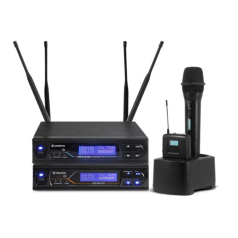
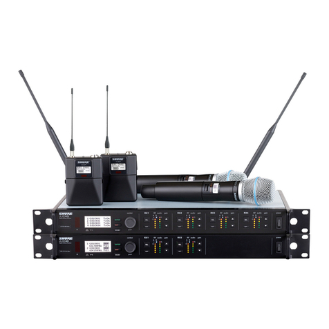
Epcom PROAUDIO SF-354UH User manual

Quad-channel wireless microphone
system
SF-354UH
User Manual

1
Index
UHF 4G Receiver………………………………………………………1
UHF Receiver Module Controls Features &Indicators…………2~5
Handheld Transmitter Controls, Features and Indicators………6~7
Body-Pack Transmitter Controls, Features and Indicators……8~10
Specification…………………………………………………………11

2
Thank you for purchasing Quad-channel wireless microphone
system. Before set up the system, read the manual carefully
to understand each part of the system.
The 4-channel wireless microphone system consists of 4sets
independent UHF receiver module with 100 frequencies from
700-900MHz. It is designed for conference room, school, church and
many other indoor applications. To get your system up and running in
just afew minutes, please follow the simple instructions in this
manual. For more information, refer to the sections of this manual that
applies to your needs.

3
UHF 4-Channel Receiver
View of Front Panel
View of Back Panel
DC INPUT
ANT3+4
12-15V
ANT1+2
BAL 4 OUT
UNBAL
OUT
BAL 3 OUT BAL 2 OUT BAL 1 OUT
800mA
4 5 5 6 5 5 4 7
①Rack mountable kit
②Power switch
③UHF receiver module
④Antenna
⑤Audio balanced output for each module
⑥4-module unbalanced shared/mixed aaudio output jack
⑦Power jack: 12V DC/ 1,000 mA
UHF Receiver Module:Features &Indicators
I. View of Front Panel
①ACT(Automatic Channel Targeting) transmission window. To make
①
②
③
④
⑤
⑥
⑦

4
the easiest and fastest channel set up between the transmitter and
receiver.
②Volume Controller
③LCD Display shows Frequency/Channel, RF signals, Audio
Signal strength, Squelch
④⑤⑥Function Keys:Press the key and hold for 2-3 seconds, then
the key is selected, Press “◄” or “►” to select function, after the
Function (frequency /channel/ Squelch) is selected, press the SET
key again to confirm it.
⑦Power Switch: Press power key for 2-3 seconds. The LCD dis-
play should light up or power off.
Squelch: Sensitivity Control sets sensitivity point at which the receiver
should be on the LCD. This control is factory pre-set at: 0-40dB from
5, 10, 15, 20, 25, 30, 35, 40, 45 dB position is to provide optimal
operation in most applications. 40 dB position will decrease operating
range.
II. Operation Each Receiver Module
1. Make sure that the transmitter is turned off before turning the
receiver power on. Press the receiver power key, the LCD will glow
and turn on. Then press “◄” or “►”to choose function and channel,
press SET key to confirm the set. Check RF and AF signal strength
when the transmitter signal becomes noisy, weak or fails. Then
press “◄” or “►” to choose aclearer channel, press SET key to
confirm.
2. Press and hold the power key for 3seconds to turn the receiver off.

5
III. Operation of the LCD display
①RF bar indicators: 8-bar indicates the strength of radio frequency
signal
②AF bar indicators: 8-bar indicates the strength of audio signal
③When frequency shows: FREQU indicates the current working
frequency
④When channel shows: CHANNL indicates the current working
channel
⑤6-segment shows: frequency, channel and menu.
⑥Mute sign shows that no RF signal is received.
Press and hold “SET”key to choose or confirm. Press“◄” or
“►”key to change current frequency or channel then press “SET”key
again to confirm it. Use “SET”key to confirm transmitter working
status. Press and long hold the “◄” or “►”for afast move.
When the strength sign shows and the frequency is the same as
shown on the transmitter, it means the pairing is done successfully.
LCD Display
A. Main Menu
Press “SET“key,the picture below will present on display first

6
After 2-3 seconds, one of two pictures below will present: it
depends on last status before turning the system off. The CPU of
receiver keeps last status in the memory, LCD displays what stored
last time when the CPU was shut off.
You can select CHANNL or FREQU when press “◄” or “►”key. It
shows 0-99 digits when choose CHANNL; it shows real carrier
frequency when you choose FREQU.
After your choice,Press “SET”key to confirm it,if you do not
press SET to confirm it, the receiver will return to last status to work.
The LCD will blink if no confirmation is made; this is to invite a
confirmation. If you press SET key to confirm it, the LCD will stay firm.
B. How to adjust channel
Press “SET”key for 2-3 seconds, LCD will present, CH 001.
Press “◄” or “►” key to change current channel. Press “SET”key to
confirm, but the receiver will return to last channel to work after
indicator flash 2-3 seconds if not press “SET”key.
(The LCD will display one of the above depends on last status)

7
C. How to adjust frequency
Press “SET”key for 2-3 seconds; LCD will present 798.000.
Press “◄” or “►” key to change current work frequency, Press “SET”
key to confirm, but the receiver will return to last state to work after
indicator flash 2-3 seconds if not to press “SET”key.
D. System lock operation
Press “SET”key for 2-3 seconds, LCD will present as the
following diagram.
After 2-3 seconds, LCD will change to one of the following
diagrams.
It depends on the last status when LCD was turned to see which one
is now.
If the LCD shows LOC ON, you can do nothing on the system,
even you cannot power off the system. If it shows LOC OFF, you can
make changes.
If it is in LOCK ON mode, press “SET”key for 2-3 seconds, then
press “◄” or “►” key to set to LOC OFF. You can change function at
LOC OFF status. Unless press “SET”key to confirm it after changing
function, otherwise receiver CPU keeps last status.

8
Trouble shootings
Some problems and their solutions are identified in the table below.
Problem Solution
LCD not glowing Check for proper connection between
power adapterand receiver
No RF signal
on receiver
Check both transmitter and receiver
channel/frequency correction
No AF signal
on receiver
Check microphone audio cable connected
body-pack, make sure output cable from
receiver is connected
Noise from receiver
When transmitter is off
Change frequency /channel, and lower
sensitivity on receiver
Audio signal distorted Decrease audio gain in transmitter and
lower audio output in receiver
Short performance
Distance and drop
RF signal
Switch transmitter output power in hi
position and set more sensitivity in
receiver or channel frequency/channel
Try to set up another pair of channel to test.

9
System Specification
Frequency Range: UHF range.700-900MHz
Modulation Mode: PLL
Bandwidth: 50 MHz
Channel: 200 Channel interval 250 KHz
Stability: +/-0.0005%
Dynamic Range: 100dB
Max Deviation: +/-80 KHz
Frequency Response: 100Hz-15 KHz+/-3dB
S/N: >105dB
Distortion: <0.5%
Operation temperature -10℃~40℃
T.H.D: <0.5% (at 10KHz Deviation)
Power Supply: DC 12V
Audio output: Balanced each&Mixed unbalanced
LCD displays: Accumulative working time after battery
Replacement, frequency, RF input level, AF level, battery status
Muting RF level and wireless channel information.
