Leuze electronic DDLS 508 User manual

Original operating instructions
EN 2016/11 - 50133576
We reserve the right to
make technical changes
DDLS 508
Optical Data Transmission for 100 Mbit/s
Ethernet – Version F3/F4

Table of contents
Leuze electronic DDLS 508 3
Table of contents
1 About this document ............................................................................................5
1.1 Used symbols and signal words ............................................................................................. 5
2 Safety .....................................................................................................................7
2.1 Intended use ........................................................................................................................... 7
2.2 Foreseeable misuse ............................................................................................................... 7
2.3 Competent persons ................................................................................................................ 8
2.4 Disclaimer ............................................................................................................................... 8
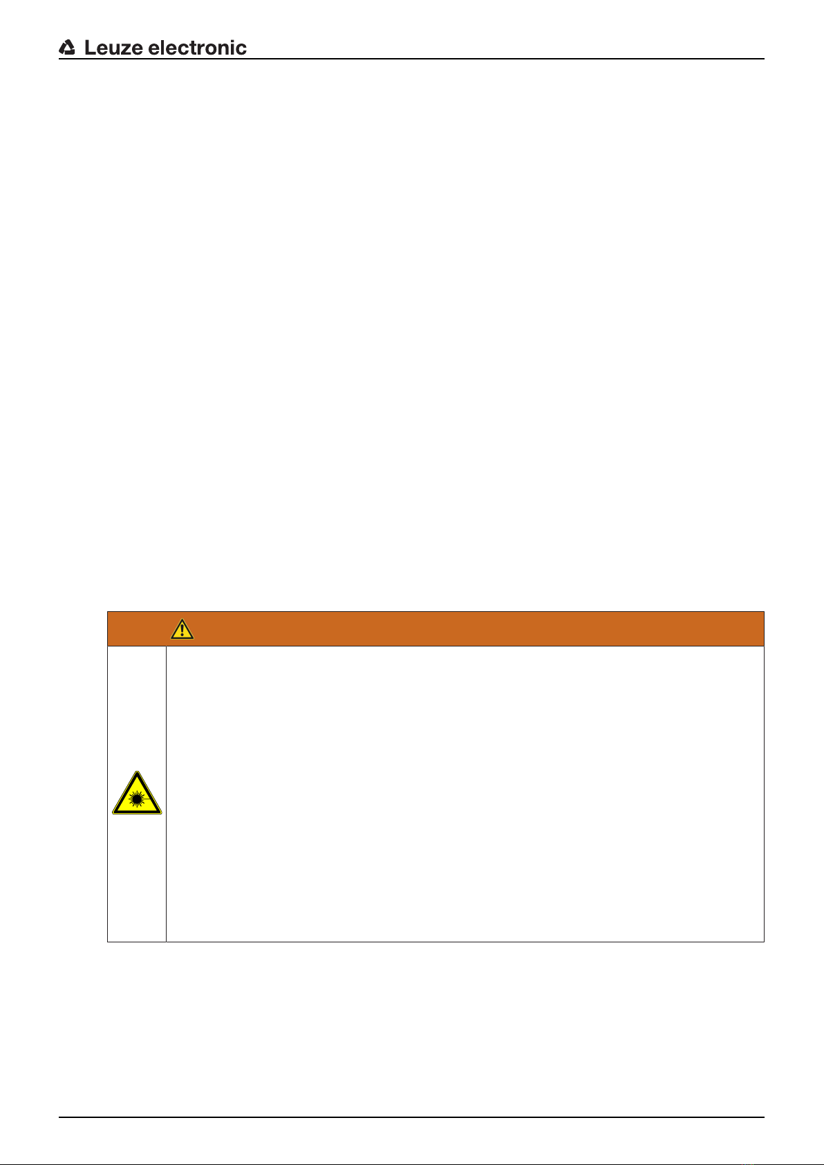
2.5 Laser safety notices................................................................................................................8
3 Device description ..............................................................................................11
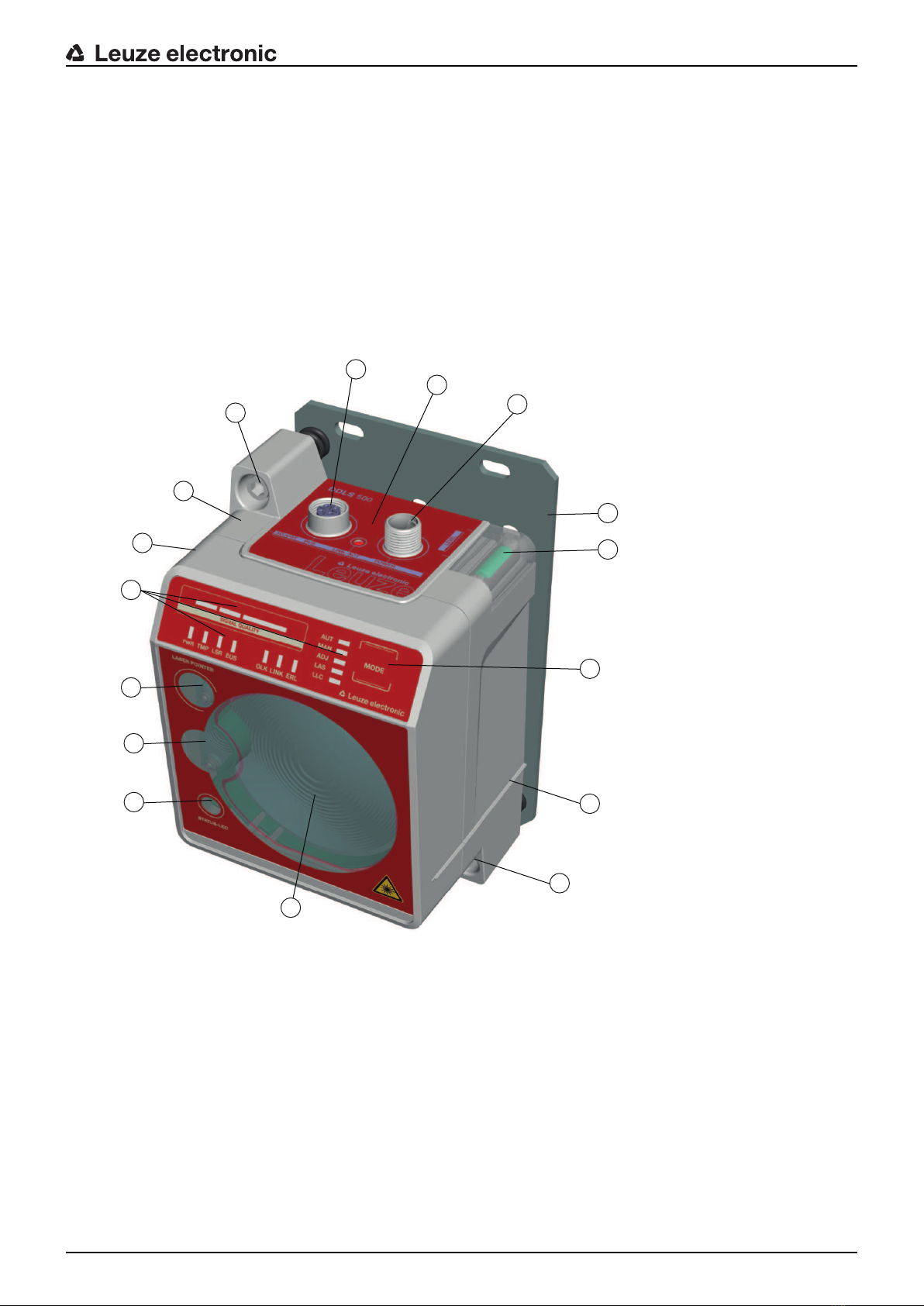
3.1 Device overview....................................................................................................................11
3.1.1 General information...........................................................................................................11
3.1.2 Performance characteristics and delivery options.............................................................12
3.1.3 Accessories .......................................................................................................................12
3.1.4 Operating principle ............................................................................................................12
3.2 Connection technology ......................................................................................................... 13
3.3 Indicators and operational controls....................................................................................... 13
3.3.1 Indicators and operational controls in the control panel .................................................... 13
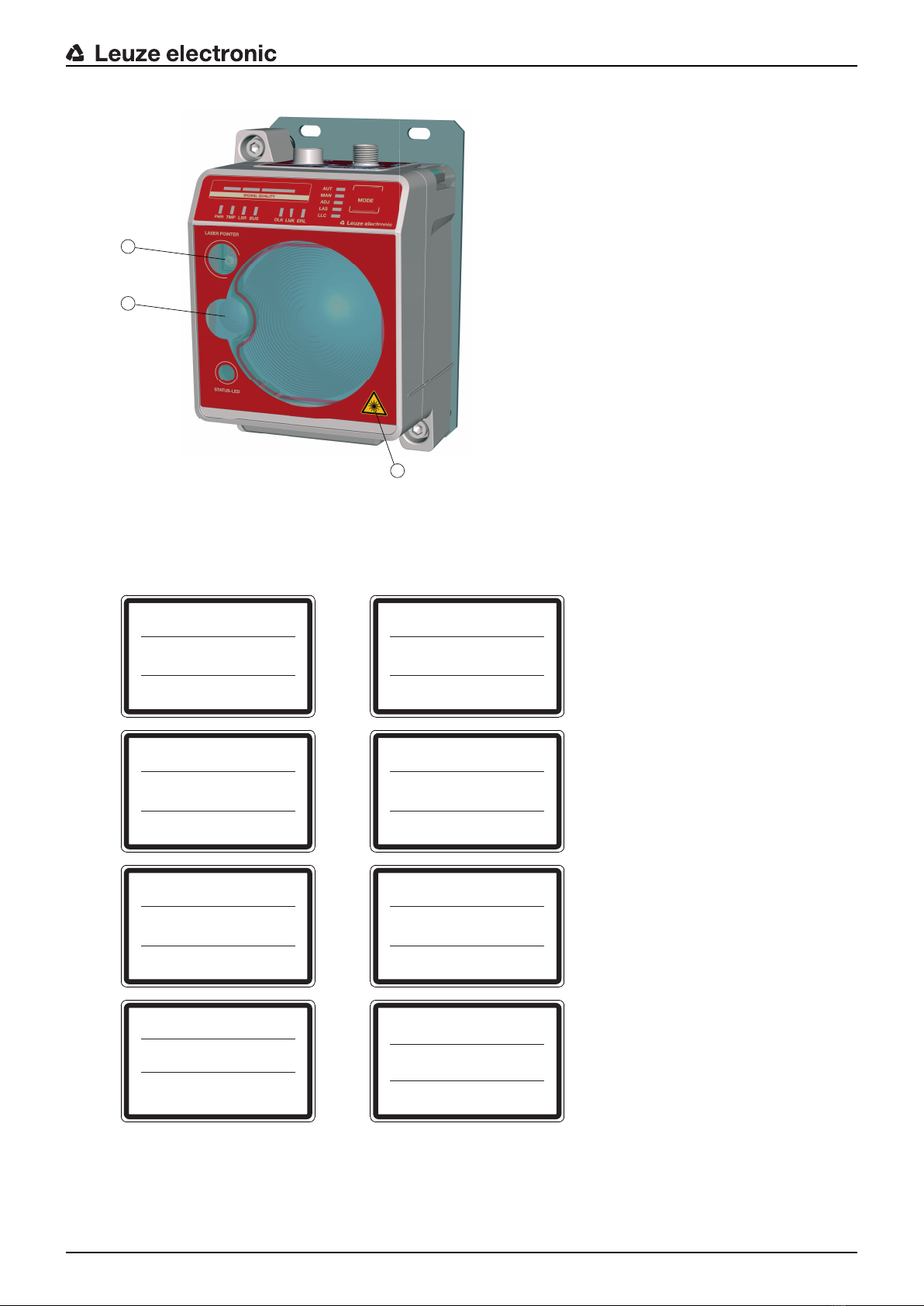
3.3.2 Indicators in the optics area ..............................................................................................20
3.3.3 Indicators in the connection area ......................................................................................21
4 Mounting..............................................................................................................22
4.1 Mounting instructions............................................................................................................ 22
4.2 Mounting with alignment laser and level............................................................................... 23
4.2.1 Horizontal mounting (travel axis) with the alignment laser ................................................ 23
4.2.2 Vertical mounting (lifting axis) with the alignment laser.....................................................28
4.3 Mounting without alignment laser ......................................................................................... 29
4.3.1 Horizontal mounting (travel axis) without alignment laser .................................................30
4.3.2 Vertical mounting (lifting axis) without alignment laser......................................................30
4.4 Mounting tolerances of the devices ...................................................................................... 32
4.5 Mounting distance for parallel operation of data transmission systems ............................... 33
4.6 Mounting distance for parallel operation with AMS300/AMS200 laser measurement sys-
tems ...................................................................................................................................... 35
4.7 Mounting distance for parallel operation with DDLS200 data transmission system ............ 35
4.8 Cascading (series connection) of multiple data transmission systems................................. 35
5 Electrical connection..........................................................................................37
5.1 Overview ............................................................................................................................... 37
5.2 POWER (supply voltage / switching input and switching output) ......................................... 38
5.3 BUS (bus input, Ethernet)..................................................................................................... 39
6 Starting up the device ........................................................................................40
6.1 Setting the operating mode................................................................................................... 40
6.2 Fine adjustment .................................................................................................................... 42
6.2.1 General procedure ............................................................................................................42
6.2.2 Fine adjustment with the single-handed adjustment (SHA) process................................. 42
6.2.3 Fine adjustment without the single-handed adjustment (SHA) process............................ 44
7 Diagnostics and troubleshooting......................................................................46
7.1 Error displays of the operating state LEDs ........................................................................... 46
7.2 Error displays and STATUS LED for remote diagnosis ........................................................ 49
7.3 Error displays of the operating mode LEDs .......................................................................... 49

Table of contents
Leuze electronic DDLS 508 4
8 Care, maintenance and disposal .......................................................................51
8.1 Cleaning................................................................................................................................ 51
8.2 Servicing ............................................................................................................................... 51
8.3 Disposing .............................................................................................................................. 51
9 Service and support ...........................................................................................52
9.1 What to do should servicing be required? ............................................................................ 52
10 Technical data .....................................................................................................53
10.1 General specifications .......................................................................................................... 53
10.1.1 Device without heater........................................................................................................53
10.1.2 Device with heating ...........................................................................................................55
10.2 Dimensioned drawings ......................................................................................................... 56
10.3 Dimensional drawings: Accessories ..................................................................................... 58
11 Order guide and accessories.............................................................................59
11.1 Nomenclature ....................................................................................................................... 59
11.2 Cables accessories............................................................................................................... 59
11.3 Other accessories................................................................................................................. 60
12 EC Declaration of Conformity............................................................................61

About this document
Leuze electronic DDLS 508 5
1 About this document
1.1 Used symbols and signal words
Tab.1.1: Warning symbols and signal words
Symbol indicating dangers to persons
Symbol indicating dangers from harmful laser radiation
Symbol indicating possible property damage
NOTE Signal word for property damage
Indicates dangers that may result in property damage if the measures for
danger avoidance are not followed.
CAUTION Signal word for minor injuries
Indicates dangers that may result in minor injury if the measures for danger
avoidance are not followed.
WARNING Signal word for serious injury
Indicates dangers that may result in severe or fatal injury if the measures
for danger avoidance are not followed.
Tab.1.2: Other symbols
Symbol for tips
Text passages with this symbol provide you with further information.
Symbol for action steps
Text passages with this symbol instruct you to perform actions.
Symbol for action results
Text passages with this symbol describe the result of the preceding action.

About this document
Leuze electronic DDLS 508 6
Tab.1.3: Terms and abbreviations
DDLS Optical transceiver for digital data transmission
EN European standard
FE Functional earth
IO or I/O Input/Output
MAC address Media Access Control address; hardware address of a device in the net-
work
NEC National Electric Code; safety standard for electrical installations in the
U.S.A.
PELV Protective Extra-Low Voltage; protective extra-low voltage with reliable dis-
connection
HBS High-bay storage device
SHA Single-Handed Adjustment; fine adjustment of the devices by one person
TCP/IP Transmission Control Protocol/Internet Protocol; Internet protocol family
UDP User Datagram Protocol; network transmission protocol
UL Underwriters Laboratories

Safety
Leuze electronic DDLS 508 7
2 Safety
This optical data transmission system was developed, manufactured and tested in line with the applicable
safety standards. It corresponds to the state of the art.
2.1 Intended use
Devices of the DDLS500 series have been designed and developed for the optical transmission of data in
the infrared range.
Areas of application
Devices of the DDLS500 series are designed for the following areas of application:
• Data transmission between stationary and/or moving devices. The devices must – with respect to the
transmission beam spread - be positioned opposite one another without interruption. A data transmis-
sion path consists of two devices designated with “FrequencyF3" and “FrequencyF4".
• Data transmission between two mutually opposing devices, whereby each device can rotate 360°. The
middle axes of the receiver lenses must – with respect to the transmission beam spread – be posi-
tioned opposite one another without interruption during the rotation.
For rotary transmission, a minimum distance of 500mm is necessary between the two devices.
NOTICE
For information about possible restrictions regarding the transmission of special protocols see
chapter 3.1.2 "Performance characteristics and delivery options".
CAUTION
Observe intended use!
The protection of personnel and the device cannot be guaranteed if the device is operated in a
manner not complying with its intended use.
ÄOnly operate the device in accordance with its intended use.
ÄLeuzeelectronicGmbH+Co.KG is not liable for damages caused by improper use.
ÄRead these operating instructions before commissioning the device. Knowledge of the oper-
ating instructions is an element of proper use.
NOTICE
Comply with conditions and regulations!
ÄObserve the locally applicable legal regulations and the rules of the employer's liability insur-
ance association.
2.2 Foreseeable misuse
Any use other than that defined under "Intended use" or which goes beyond that use is considered im-
proper use.
In particular, use of the device is not permitted in the following cases:
• in rooms with explosive atmospheres
• for medical purposes
NOTICE
Do not modify or otherwise interfere with the device!
ÄDo not carry out modifications or otherwise interfere with the device. The device must not be
tampered with and must not be changed in any way.
ÄThe device must not be opened. There are no user-serviceable parts inside.
ÄRepairs must only be performed by Leuze electronic GmbH + Co. KG.

Safety
Leuze electronic DDLS 508 8
2.3 Competent persons
Connection, mounting, commissioning and adjustment of the device must only be carried out by competent
persons.
Prerequisites for competent persons:
• They have a suitable technical education.
• They are familiar with the rules and regulations for occupational safety and safety at work.
• They are familiar with the original operating instructions of the device.
• They have been instructed by the responsible person on the mounting and operation of the device.
Certified electricians
Electrical work must be carried out by a certified electrician.
Due to their technical training, knowledge and experience as well as their familiarity with relevant standards
and regulations, certified electricians are able to perform work on electrical systems and independently de-
tect possible dangers.
In Germany, certified electricians must fulfill the requirements of accident-prevention regulations BGV A3
(e.g. electrician foreman). In other countries, there are respective regulations that must be observed.
2.4 Disclaimer
LeuzeelectronicGmbH+Co.KG is not liable in the following cases:
• The device is not being used properly.
• Reasonably foreseeable misuse is not taken into account.
• Mounting and electrical connection are not properly performed.
• Changes (e.g., constructional) are made to the device.
2.5 Laser safety notices
Laser diode of the transmitter – laser class 1M
WARNING
INVISIBLE LASER RADIATION – LASER CLASS 1M
Never observe directly using telescope optics!
The device fulfills the IEC60825-1:2007 (EN60825-1:2007) requirements for a product in laser
class1M as well as the U.S.21CFR1040.10 regulations with deviations corresponding to
"Laser Notice No.50" from June 24th, 2007.
ÄLooking into the beam path for extended periods using telescope optics may damage the
eye's retina. Never look using telescope optics into the laser beam or in the direction of re-
flecting beams.
ÄCAUTION! The use of operating or adjusting devices other than those specified here or car-
rying out of differing procedures may lead to dangerous exposure to radiation.
The use of optical instruments or devices (e.g., magnifying glasses, binoculars) with the
product will increase eye danger.
ÄObserve the applicable statutory and local laser protection regulations.
ÄThe device must not be tampered with and must not be changed in any way.
There are no user-serviceable parts inside the device.
Repairs must only be performed by Leuze electronic GmbH + Co. KG.
The device emits invisible laser radiation with a wavelength of 785nm (device with designation “Fre-
quencyF3") or 852nm (device with designation “FrequencyF4") through the laser aperture of the optical
window. The opening angle of the beam cone is ≤1° (± 0.5°).
The power density distribution in the light spot is homogeneous; there is no elevation of power density in
the center of the light spot. The average emitted laser power of the device is <12mW. For transmission of
the data, the emitted laser radiation is amplitude modulated (on-off keying). Pulses and pulse pauses of the
emitted laser light are between 8ns and 32ns long. The laser power emitted during the pulses is <24mW.

Safety
Leuze electronic DDLS 508 9
1
2
3
1 Laser aperture – alignment laser
2 Laser aperture – transmitter
3 Laser warning sign
Fig.2.1: Laser apertures
UNSICHTBARE LASERSTRAHLUNG
Nicht direkt mit Teleskopoptiken betrachten!
LASER KLASSE 1M
DIN EN 60825-1:2008-05
Max. Leistung (peak):
Impulsdauer:
Wellenlänge:
RADIAZIONE LASER INVISIBILE
Nonguardaredirettamentecon ottichetelescopiche!
APARRECCHIO LASER DI CLASSE 1M
EN 60825-1:2007
Potenza max. (peak):
Durata dell'impulso:
Lunghezza d'onda:
< 36 mW
32
n
s
785 nm
< 36 mW
32
n
s
785 nm
INVISIBLE LASER RADIATION
Never observe directly using telescope optics!
CLASS 1M LASER PRODUCT
EN 60825-1:2007
Maximum Output (peak):
Pulse duration:
Wavelength:
RAYONNEMENT LASER INVISIBLE
Nepas regarderdirectementavec desoptiquestélescopiques!
APPAREIL À LASER DE CLASSE 1M
EN 60825-1:2007
Puissance max. (crête):
Durée d`impulse:
Longueur d`ande émis:
< 36 mW
32
n
s
785 nm
< 36 mW
32
n
s
785 nm
RADIACIÓN LÁSER INVISIBLE
¡No mirar directamente con ópticas telescópicas!
PRODUCTO LÁSER DE CLASE 1M
EN 60825-1:2007
Potencia máx. (peak):
Duración del impulso:
Longitud de onda:
RADIACAO LASER INVISIVEL
Não olhe diretamente para as óticas telescópicas!
EQUIPAMENTO LASER CLASSE 1M
EN 60825-1:2007
Potência máx. (peak):
Período de pulso:
Comprimento de onda:
< 36 mW
32
n
s
785 nm
< 36 mW
32
n
s
785 nm
INVISIBLE LASER RADIATION
Never observe directly using telescope optics!
CLASS 1M LASER PRODUCT
IEC 60825-1:2007
Complies with 21 CFR 1040.10
Maximum Output (avg):
Pulse duration:
Wavelength: ⺞㉒匘䧋䦚ₜⒿ䤓䉏⏘⺓兎䰐㷱抩扖㦪扫柫屑䦚1M伊䉏⏘ℶ❐GB7247.1-2001
㦏⮶戢⒉᧤⽿⋋᧥厘⑁㖐兼㢅梃㽱栎< 36 mW
32
n
s
785 nm
< 36 mW
32
n
s
785 nm
Fig.2.2: Laser warning and laser information signs for devices with frequencyF3

Safety
Leuze electronic DDLS 508 10
UNSICHTBARE LASERSTRAHLUNG
Nicht direkt mit Teleskopoptiken betrachten!
LASER KLASSE 1M
DIN EN 60825-1:2008-05
Max. Leistung (peak):
Impulsdauer:
Wellenlänge:
RADIAZIONE LASER INVISIBILE
Nonguardaredirettamenteconottiche telescopiche!
APARRECCHIO LASER DI CLASSE 1M
EN 60825-1:2007
Potenza max. (peak):
Durata dell'impulso:
Lunghezza d'onda:
< 36 mW
32
n
s
852 nm
< 36 mW
32
n
s
852 nm
INVISIBLE LASER RADIATION
Never observe directly using telescope optics!
CLASS 1M LASER PRODUCT
EN 60825-1:2007
Maximum Output (peak):
Pulse duration:
Wavelength:
RAYONNEMENT LASER INVISIBLE
Nepas regarderdirectementavecdes optiquestélescopiques!
APPAREIL À LASER DE CLASSE 1M
EN 60825-1:2007
Puissance max. (crête):
Durée d`impulse:
Longueur d`ande émis:
< 36 mW
32
n
s
852 nm
< 36 mW
32
n
s
852 nm
RADIACIÓN LÁSER INVISIBLE
¡No mirar directamente con ópticas telescópicas!
PRODUCTO LÁSER DE CLASE 1M
EN 60825-1:2007
Potencia máx. (peak):
Duración del impulso:
Longitud de onda:
RADIACAO LASER INVISIVEL
Não olhe diretamente para as óticas telescópicas!
EQUIPAMENTO LASER CLASSE 1M
EN 60825-1:2007
Potência máx. (peak):
Período de pulso:
Comprimento de onda:
< 36 mW
32
n
s
852 nm
< 36 mW
32
n
s
852 nm
INVISIBLE LASER RADIATION
Never observe directly using telescope optics!
CLASS 1M LASER PRODUCT
IEC 60825-1:2007
Complies with 21 CFR 1040.10
Maximum Output (avg):
Pulse duration:
Wavelength: ⺞㉒匘䧋䦚ₜⒿ䤓䉏⏘⺓兎䰐㷱抩扖㦪扫柫屑䦚1M伊䉏⏘ℶ❐GB7247.1-2001
㦏⮶戢⒉᧤⽿⋋᧥厘⑁㖐兼㢅梃㽱栎< 36 mW
32
n
s
852 nm
< 36 mW
32
n
s
852 nm
Fig.2.3: Laser warning and laser information signs for devices with frequencyF4
Alignment laser (optional) – laser class 1
WARNING
LASER RADIATION – LASER CLASS 1
The device satisfies the requirements of IEC60825-1:2007 (EN60825-1:2007) safety regula-
tions for a product of laser class1 as well as the U.S.21CFR1040.10 regulations with devia-
tions corresponding to "Laser Notice No.50" from June 24, 2007.
ÄObserve the applicable statutory and local laser protection regulations.
ÄThe device must not be tampered with and must not be changed in any way.
There are no user-serviceable parts inside the device.
ÄRepairs must only be performed by Leuze electronic GmbH + Co. KG.
NOTICE
Devices with integrated alignment laser can be identified by part number code L in the part des-
ignation, e.g., DDLS5xxXXX.4L.
Laser class1M also applies for devices with integrated alignment laser.

Device description
Leuze electronic DDLS 508 11
3 Device description
3.1 Device overview
3.1.1 General information
The DDLS508 optical data transmission system transmits Ethernet network data on the basis of TCP/IP or
UDP transparently and without contact or wear via infrared light.
A MAC address or IP address configuration is not necessary.
A transmission path consists of two mutually opposing devices.
• One device is designated with “Frequency F3", the other with “Frequency F4".
• The devices can also be assigned via part number code DDLS5XX…3… and DDLS5XX…4….
14
3
4
5
13
6
7
2
8
10
1
11
9
16
15
12
1 Device housing 9 Connection area
2 Mounting plate 10 Operating mode selector switch
3 Planar surface for supporting a bubble level or
alignment straightedge
11 Alignment screw for vertical alignment
4 Receiver optics 12 Alignment screw for horizontal alignment
5 Transmitter optics 13 STATUS LED for remote diagnosis
6 Alignment laser for mounting support (optional) 14 Supporting edge for bubble level or alignment straight-
edge
7 LED indicators in the control panel 15 Ethernet connection, M12
8 Spirit level (for devices with alignment laser) 16 POWER connection, M12
Fig.3.1: Device construction

Device description
Leuze electronic DDLS 508 12
3.1.2 Performance characteristics and delivery options
• Protocol-independent data transmission of all TCP/IP and UDP protocols, e.g.
• EtherCat (with restrictions on functions "Link Fault Pass Through" and "Distributed Clock")
• PROFINET RT
• EthernetIP (Rockwell)
• …and more
• Data transmission over a range of up to 200m
• Optional alignment laser including spirit level for mounting support
• Planar surfaces on top and side for supporting a level or alignment straightedge
• Single-handed adjustment (SHA) for aligning the devices by one person
• Optional variants with integrated heating for operating temperatures below -5°C
Use to ‑35°C
• Transmission optics with larger beam spread on request
NOTICE
The PROFINET IRT protocol is a special case. The DDLS508 cannot satisfy the specifications
of the transmission criteria for PROFINET IRT.
ÄFor details on the delay times or the jitter-relevant device data, see chapter 4.8 "Cascading
(series connection) of multiple data transmission systems".
3.1.3 Accessories
For exact details and order information, see chapter 11 "Order guide and accessories".
• Adapter plate for installing instead of a DDLS200
• Ready-made cable for M12 connections
• Customizable connector plug
3.1.4 Operating principle
A pair of devices is necessary for establishing a data transmission path. To prevent the devices from mutu-
ally interfering with one another during data transmission, they use different frequencies.
• one device with frequency F3
Part designation: DDLS5XXxxx.3YY
Designation on the name plate: FrequencyF3
• one device with frequency F4
Part designation: DDLS5XXxxx.4YY
Designation on the name plate: FrequencyF4
NOTICE
Installation for devices with an operating range of 200m.
ÄAlways install the Frequency F4 device as stationary device for devices with an operating
range of 200m (DDLS5XX200…).

Device description
Leuze electronic DDLS 508 13
12
34
1 Device with frequency F3 (DDLS5XXxxx.3YY)
2 Device with frequency F4 (DDLS5XXxxx.4YY)
3 FrequencyF3
4 FrequencyF4
Fig.3.2: Optical data transmission on two frequencies
The received signal level (SIGNALQUALITY) is measured on both devices. If the received signal level
drops below a certain value (SIGNALQUALITY indicator shows only red and orange), the intensity warning
is activated.
The intensity warning is applied on switching output IO1 of the POWER connection.
3.2 Connection technology
A-coded, M12 connection for the supply voltage with integrated switching input and output.
D-coded, M12 connection for the Ethernet connection.
3.3 Indicators and operational controls
3.3.1 Indicators and operational controls in the control panel
Operating mode selector switch and operating mode indicator
• Operating mode selector switch [MODE]
The operating mode selector switch is used to switch between the operating modes of the device (see
chapter 6 "Starting up the device").
• Operating mode LEDs AUT, MAN, ADJ, LAS, LLC
The operating mode LEDs indicate the active operating mode.

Device description
Leuze electronic DDLS 508 14
4 5
12 63
1 AUT – Automatic
2 MAN – Manual
3 ADJ – Adjust
4 LAS – Alignment laser for mounting support
5 LLC – LinkLossCounter
6 MODE – Operating mode selector switch
Fig.3.3: Operating mode LEDs and operating mode selector switch
Tab.3.1: Meaning of the operating mode indicators
LED Color State Description
AUT Green Continuous light AUT operating mode (Automatic) active
Standard operating mode for data transmission
Note:
The optical link remains activated until the last orange LED
in the SIGNALQUALITY indicator switches off.
MAN Green Continuous light MAN operating mode (Manual) active
Operating mode for fine adjustment of the devices via SHA
(see chapter 6.2.2 "Fine adjustment with the single-handed
adjustment (SHA) process").
Note:
The optical link remains activated until the last green LED in
the SIGNALQUALITY indicator switches off.
ADJ Green Continuous light ADJ operating mode (Adjust) active
Operating mode for fine adjustment of the devices via SHA
(see chapter 6.2.2 "Fine adjustment with the single-handed
adjustment (SHA) process").
Note:
• Data transmission to the connected participants is de-
activated.
• The optical link remains activated until the last orange
LED in the SIGNALQUALITY indicator switches off.
• The received signal level (SIGNALQUALITY) of the
second device is transmitted to the SIGNALQUALITY
indicator of the first device.
LAS Green Continuous light LAS operating mode (Laser Adjustment System) active
The alignment laser mounting support is activated (see
chapter 4.2 "Mounting with alignment laser and level").

Device description
Leuze electronic DDLS 508 15
LED Color State Description
LLC --- OFF LLC operating mode (LinkLossCounter, interruption diag-
nostics) not activated.
Green Continuous light The optical link was interruption-free since activation of the
LLC.
Red Continuous light The optical link was interrupted at least once since activa-
tion of the LLC (see chapter 7.3 "Error displays of the oper-
ating mode LEDs").

Device description
Leuze electronic DDLS 508 16
Operating state indicator
The PWR, TMP, LSR, OLK, ERL and LINK LEDs indicate the operating state of the device.
12 3 4 5 6 7
1 PWR – Supply voltage (Power)
2 TMP – Temperature warning/error
3 LSR – Laser prefailure message
4 BUS – Not active for DDLS508
5 OLK – Optical link
6 ERL – Error Link
7 LINK – M12 cable-connected link
Fig.3.4: Operating state LEDs in the control panel
Tab.3.2: Meaning of the operating state indicators
LED Color State Description
PWR --- OFF No supply voltage (see chapter 7.1 "Error displays of the op-
erating state LEDs")
Green Flashing Device is being initialized
• Supply voltage connected
• Initialization running
• No data sent or received
Green Continuous light Data transmission path ready
• Initialization finished
Red Flashing Warning set (see chapter 7.1 "Error displays of the operating
state LEDs")
• No green and orange LEDs in SIGNALQUALITY indica-
tor
• The optical link is interrupted.
• The laser diode of the transmitter is defective.
Red Continuous light Device error (see chapter 7.1 "Error displays of the operating
state LEDs"
• The function of the device is limited.
The displays of the other operating state LEDs may pro-
vide information on the cause of the error.

Device description
Leuze electronic DDLS 508 17
LED Color State Description
TMP --- OFF Operating temperature in the specified working range
Orange Continuous light • Warning: The operating temperature is above or below
the specified working range by a maximum of 5°C (see
chapter 7.1 "Error displays of the operating state LEDs").
• Data transmission remains active.
Red Continuous light • The operating temperature is above or below the speci-
fied working range by more than 5°C (see chapter 7.1
"Error displays of the operating state LEDs").
• The operating time outside of the permissible operating
temperature is detected by the device.
• Data transmission remains active.
LSR --- OFF Laser diode of the transmitter with sufficient function reserve.
Orange Continuous light • Warning: The laser diode of the transmitter signals the
imminent end of the life expectancy (see chapter 7.1 "Er-
ror displays of the operating state LEDs").
Limits to the maximum data transmission distance may
occur.
• Data transmission remains active.
BUS Not active for the DDLS508
OLK --- OFF No optical data connection
No data transmission
Causes (see chapter 7.1 "Error displays of the operating state
LEDs"):
• Optical window soiled
• Insufficient alignment
• Range exceeded
• Environmental influences (snow, rain, fog)
• Wrong F3/F4 frequency assignment of the devices
• Transmitter deactivated
• Transmitter of the second device deactivated
Green Continuous light • The optical link exists.
• No data is sent or received.
Orange Continuous light/
flickering light
Data is sent and received.
ERL --- OFF No link error.
Orange Continuous light • Missing link (Ethernet cable connection) on the second
device (see chapter 7.1 "Error displays of the operating
state LEDs").
• SIGNALQUALITY indicator on the second device without
green and orange LED (see chapter 7.1 "Error displays of
the operating state LEDs").
Red Continuous light • No cable-connected link to the connected device (see
chapter 7.1 "Error displays of the operating state LEDs").
• SIGNALQUALITY indicator without green and orange
LED (see chapter 7.1 "Error displays of the operating
state LEDs").

Device description
Leuze electronic DDLS 508 18
LED Color State Description
LINK --- OFF No cable-connected link to the connected device (see chapter
7.1 "Error displays of the operating state LEDs").
Green Continuous light • The link to the connected device is OK.
• No data is sent or received.
Orange Continuous light/
flickering light
• The link to the connected device is active.
• Data is sent and received.
SIGNALQUALITY indicator
Eight individual LEDs are available for displaying the received signal level (SIGNALQUALITY):
• two red LEDs
• two orange LEDs
• four green LEDs
At the optimum received signal level, all LEDs (red, orange, green) are activated.
If the received signal level drops, the LEDs are successively switched off, beginning with the green LEDs.
12 3
1 two red LEDs
2 two orange LEDs
3 four green LEDs
Fig.3.5: SIGNALQUALITY indicator of the received signal level

Device description
Leuze electronic DDLS 508 19
Tab.3.3: Meaning of the SIGNALQUALITY indicators
LED Color State Description
SIGNAL
QUALITY
Green Continuous light
4-stage
• Received signal level with function reserve.
• The optical link exists.
Orange Continuous light
2-stage
Warning: Received signal level with minimal function re-
serve (see chapter 7 "Diagnostics and troubleshooting").
• The optical link exists.
AUT operating mode (Automatic): Data transmission is
active.
MAN (Manual), ADJ (Adjust) operating modes: Data
transmission is deactivated.
• Switching output IO1 of the POWER connection is acti-
vated in operating modes AUT (Automatic), MAN (Man-
ual) and ADJ (Adjust).
Causes:
• Optical window soiled
• Range exceeded
• Environmental influences (snow, rain, fog)
• Insufficient alignment
Red Continuous light
2-stage
The optical link is interrupted. The received signal level is
not sufficient (see chapter 7 "Diagnostics and troubleshoot-
ing").
• No data is sent or received.
• Switching output IO1 of the POWER connection is acti-
vated.
Causes:
• Optical window soiled
• Range exceeded
• Environmental influences (snow, rain, fog)
• Insufficient alignment of the devices
• Wrong F3/F4 frequency assignment of the devices
• Transmitter of the second device deactivated

Device description
Leuze electronic DDLS 508 20
3.3.2 Indicators in the optics area
For simple, quick diagnosis, the device is equipped with a STATUS LED in the optics area.
The STATUS LED enables a quick summary diagnosis of the operating state of the device.
• The STATUS LED summarizes the displays of the individual LEDs of the control panel in a single indi-
cator.
• The STATUS LED illuminates very brightly and can also be seen from a relatively long distance.
1
1 STATUS LED
Fig.3.6: STATUS LED in the optics area
Tab.3.4: Meaning of the STATUS LED display
LED Color State Description
STATUS
LED
Green Continuous light Not a warning or error message.
Green Flashing There is/are warning message(s) (see chapter 7.2 "Error dis-
plays and STATUS LED for remote diagnosis"):
• SIGNALQUALITY indicator without green LED in operating
modes AUT (Automatic), MAN (Manual), ADJ (Adjust)
• Temperature, warning or error (TMP)
• Laser pre-failure (LSR)
• LinkLossCounter has triggered (LLC)
Data transmission is active.
--- OFF • No supply voltage.
• SIGNALQUALITY indicator shows only red LEDs.
• The LINK and LINK/ACT LEDs are off.
• The transmitter is deactivated (see chapter 7.2 "Error dis-
plays and STATUS LED for remote diagnosis").

Device description
Leuze electronic DDLS 508 21
3.3.3 Indicators in the connection area
For the status display of the Ethernet connection, the device is equipped with a split, two-colored LINK/ACT
LED in the connection area.
The LINK/ACT LED indicates the same state as the LINK LED in the control panel.
1
1 LED, Ethernet (split, two-colored) LINK/ACT
Fig.3.7: LINK/ACT LED in the connection area
Tab.3.5: Meaning of the LINK/ACT displays
LED Color State Description
LINK/ACT --- OFF No cable-connected link to the connected device (see chapter
7.1 "Error displays of the operating state LEDs").
Green Continuous
light
• The link to the connected device is OK.
• No data is sent or received.
Orange Continuous
light/
flickering light
• The link to the connected device is active.
• Data is sent and received.
Other manuals for DDLS 508
1
Table of contents
Other Leuze electronic Microphone System manuals