manuals.online logo
Brands
  1. Home
  2. •
  3. Brands
  4. •
  5. Epever
  6. •
  7. Controllers
  8. •
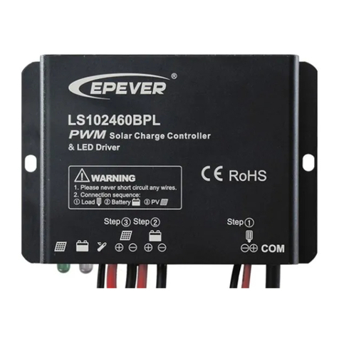
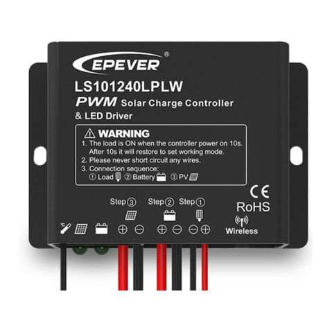
  9. Epever LandStar BPL Series User manual

Epever LandStar BPL Series User manual

BEIJING EPSOLAR TECHNOLOGY CO., LTD. Tel:+86-10-82894112 / 82894962 Website:www.epsolarpv.com/www.epever.com
1 2
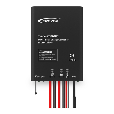
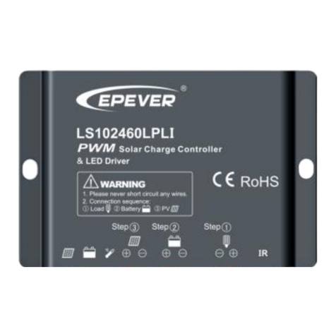
LandStar BPL Series Solar Charge Controller
---with built in LED Driver
1. Safety Information
Read all of the instructions in the manual before installation.
DO NOT disassemble or attempt to repair the controller.
Install external fuse or breaker as required.
Do disconnect the solar module and fuse/ breakers near to battery before installing
or moving the controller.
Power connections must remain tight to avoid excessive heating from a loose
connection.
Only charge batteries that comply with the parameters of controller.
Battery connection may be wired to one battery or a bank of batteries.
Risk of electric shock, the PV and load can produce high voltages when the
controller is working.
2. Overview
Thank you for selecting the LandStar BPL series solar charge controller. It combines
solar charge controller and LED constant current driver into one unit which is ideal for
solar LED Lighting, especially when dimmer function is needed. The control
parameter can be programmed via Mobile APP, PC Monitor setting software with
RS485 communication interface. The features are listed below:
12/24VDC automatically identifying system voltage or user-defined working voltage
3-Stage intelligent PWM charging:Bulk, Boost/Equalize, Float
Support 4 charging options: Sealed, Gel, Flooded and user
Battery temperature compensation function
Digital precision constant current control and the control accuracy are less than 30mA
Maximum output efficiency of 96.7%
The output current can be adjusted among the rated power and current range
Intelligent power mode with 365-day lighting control technology
Load test function for detecting the system
Multiple load control modes
Extensive Electronic protection
Monitoring and setting parameter via Mobile APP, PC Monitor setting software with
RS485 communication interface
Use of standard Modbus communication protocol for RS485 bus connections,
communication protocol compatibility much better
Connecting the IOT(Internet of Things) module and Cloud Server monitoring software
to realize remote monitoring of the multi-machine system
The RS485 connector can provide power supply
Aluminum housing for better cooling
IP67 waterproof degree
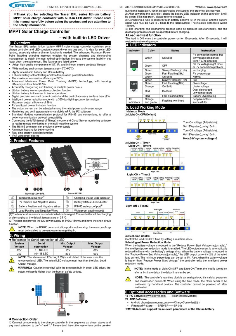
3. Product Features
①
Charging Status LED indicator
⑥
Load Positive and Negative Wires
②
Battery Status LED indicator
⑦
RS485 waterproof connector⑫
③
Temperature Sensor⑪
⑧
Port waterproof cap(Included)
④
PV Positive and Negative Wires
⑨
Pin definition
⑤
Battery Positive and Negative Wires
⑩
Mounting hole
⑴The temperature sensor short-circuited or damaged, the controller will be
charging or discharging at the default temperature 25 ºC.
⑵The connector can provide that the voltage is 5V and the current is 150mA. The
pin define is shown above picture.
4. Wiring
1) Connect components to the charge controller in the sequence as shown above and
pay much attention to the “+” and “-”. Please don’t insert the fuse or turn on the breaker
during the installation. When disconnecting the system, the order will be reserved.
2) After power on the controller, check the battery LED indicator on the controller, it will
be green. If it’s not green, please refer to chapter 9.
3) Connecting a fuse in series through battery positive (+) in the circuit and the battery
circuit fuse must be 1.25 to 2 times to the rated current. The installed distance is within
150mm.
5. LED Indicators
Indicator
Color
Status
Instruction
Green
On Solid
PV connection normal
but low
voltage(irradiance)
from PV, no charging
Green
OFF
No PV voltage(night
time) or PV connection
problem
Green
Slowly Flashing(1Hz)
In charging
Green
Fast Flashing(4Hz)
PV reverse polarity
Green
On Solid
Normal
Green
Slowly Flashing(1Hz)
Full
Green
Fast Flashing(4Hz)
Over voltage
Orange
On Solid
Under voltage
Red
On Solid
Over discharged
Red
Slowly Flashing(1Hz)
Battery Overheating
Charging (green) and battery indicator (orange)
flashing simultaneously
Controller overheating
Charging (green) and battery indicator (red)
flashing simultaneously
System voltage error
6. Setting Operation
Load Set
1) Manual Mode
2) Light ON/OFF(Default)
3) Light ON + Timer
Light ON + Timer1
Light ON + Timer2
Light ON + Timer3
4) Real-time Control
Control the load ON/OFF time through setting real-time clock.
5) Intelligent Power Mode
When the battery voltage is lower than “Under Warning Recover Voltage (UWRV
adjustable)”, the intelligent power mode is enabled; at this time, the LED current
percentage will be automatically reduced in linear with the voltage drop of battery. When
the battery voltage is lower than “Under Warning Recover Voltage (WRW adjustable)”, a
minimum LED current percentage (default 2%, adjustable) will be output. In addition,
when the battery voltage is higher than UWRV, the controller will exit the intelligent
power mode.
Thank you for selecting the LandStar BPL series solar charge
controller. Please read this manual carefully before using the
product and pay attention to the safety information.
BEIJING EPSOLAR TECHNOLOGY CO., LTD. Tel:+86-10-82894112 / 82894962 Website:www.epsolarpv.com/www.epever.com
3 4
NOTE:The load is ON when the controller power on 1seconds. After 1
seconds it will restore to set working mode.
NOTE: In the mode of Light ON/OFF and Light ON/Timer, the Load is
turned on after 1Min. delay.
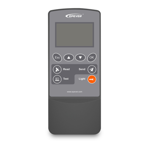
7. Accessories(optional) and Software
1)PC Software
www.epever.com ——Solar Station Monitor
2)APP Software
Android phone
www.epever.com——ChargeController(Sealed)
IPhone
APP Store——EPEVER——EP-01
※Specific instructions refer to the list of accessories and software.
8. Protection
PV Short Circuit
If the PV array short circuit, the controller will stop charging, clear it to resume normal
operation.
PV Reverse Polarity
Fully protection against PV reverse polarity, correct the wire connection to resume
normal operation.
Battery Reverse Polarity
Fully protection against battery reverse polarity, correct the wire connection to
resume normal operation.
Battery Over Voltage
When the battery voltage reaches to the set point of Over Voltage Disconnect Voltage,
the controller will stop charging the battery to protect the battery from being over
charged to break down.
Battery Over Discharge
When the battery voltage reaches to the set point of Low Voltage Disconnect Voltage,
the controller will stop discharging the battery to protect the battery from being over
discharged to break down.
Battery Overheating
The controller detect the environment temperature through the external temperature
sensor. If the environment temperature exceeds 65 ºC , the controller will
automatically start the overheating protection to stop working, and recover below
50 ºC .
Load Short Circuit
Load will be switched off when load short circuit (≥4 times rated current) happens.
Controller will automatically attempt to reconnect load for 5 times. If short circuit
protection still exist after controller’s 5 times attempts, user have to clear short
circuit ,then restart the controller or wait for one night-day cycle (night time>3 hours).
Controller Overheating
If the temperature of the controller exceeds 85 ºC , the controller will automatically
start the overheating protection, and recover below 75 ºC .
High Voltage Transients
The controller is protected against small high voltage transients. In lightning prone
areas, additional external suppression is recommended.
9. Troubleshooting
Faults
Possible reasons
Troubleshooting
LED Charging
indicator turn off
during daytime
when sunshine falls
on PV modules
properly
PV
array disconnection
Confirm that PV and battery wire
connections are correct and tight
No LED indicator
Battery voltage maybe
less than 9V
Measure battery voltage with the
multi-meter. Min.9V can start up the
controller
Battery LED
indicator green fast
Flashing
Battery over voltage
Check if battery voltage is higher
than OVD, and disconnect the PV
Battery LED
indicator red
Battery
over discharged
When the battery voltage is restored
to or above LVR point (low voltage
reconnect voltage), the load will
recover
Battery LED
indicator red
flashing
Battery Overheating
The controller will automatically turn
the system off. But while the
temperature decline to be below 50
ºC, the controller will resume.
Charging(green)
and battery
indicator
(orange)flashing
simultaneously
Controller overheating
please try to decline the
environment’s temperature, or the
power of PV or the power of the load
System voltage error
Check whether the battery voltage
match with the controller’s working
voltage, If not please change to a
suitable battery or reset the working
voltage
Powering on
normally, the load is
off
①The connecting
wires are error or
virtually connected
①Check the connecting cable.
②Check the load’s mode and
parameters.
②Load mode is not
appropriate.
③This controller does
not match with the LED
light.
④Output short circuit.
③The voltage of LED light is not
within the output voltage range of
controller.
④Check the connecting cables and
LED light.
The dimming
function is invalid
The controller does not
match with the LED
light source. This
product is a step-up
voltage control, If input
voltage is lower than
the rated voltage, it is
not working.
①Replace the LED light
②Reduce system rated voltage
grade and replace the product
model
For example 24V system change to
12V system, and replace the
corresponding controller
10. Technical Specifications
Item
LS102460BPL
LS2024100BPL
Nominal system voltage
12/24VDC Auto
Battery input voltage range
9V~32V
Max. PV open circuit voltage
50V
Rated charge current
10A
20A
Max. output current
2.0A
3.3A
Max. output power
30W/12V;60W/24V
50W/12V;100W/24V
Output voltage range
Max. battery voltage+2V~60V
Load open circuit voltage
60V
Max. output efficiency
96.7%
Output current control
accuracy
≤30mA
Battery Type
Sealed(default)/Gel/Flooded/User
Self-consumption
≤11mA/12V;≤9mA/24V
Charge Circuit Voltage Drop
≤0.3V
Temperature compensation
coefficient
-3mV/℃/2V
Working environment
temperature
-35℃~+55℃
Enclosure
IP67
Grounding
Common Positive
Overall dimension
107x73x20mm
108.5x102x25.6mm
Mounting dimension
100mm
100.5x80mm
Mounting hole size
Φ4
Φ5
Power cable
PV/BAT: 14AWG(2.5mm2)
LOAD: 18AWG(1.0mm2)
PV/BAT:12AWG(4.0mm2)
LOAD: 18AWG(1.0mm2)
Net weight
0.28kg
0.46kg
Battery Voltage Control Parameters (below parameters are in 12V system at 25 ºC,
please double the values in 24V system)
Battery Type Select
Sealed
Gel
Flooded
User
Over Voltage Disconnect Voltage
16.0V
16.0V
16.0V
9~17V
Charging Limit Voltage
15.0V
15.0V
15.0V
9~17V
Over Voltage Reconnect Voltage
15.0V
15.0V
15.0V
9~17V
Equalize Charging Voltage
14.6V
——
14.8V
9~17V
Boost Charging Voltage
14.4V
14.2V
14.6V
9~17V
Float Charging Voltage
13.8V
13.8V
13.8V
9~17V
Boost Reconnect Charging Voltage
13.2V
13.2V
13.2V
9~17V
Low Voltage Reconnect Voltage
12.6V
12.6V
12.6V
9~17V
Under Voltage Warning Reconnect
Voltage
12.2V
12.2V
12.2V
9~17V
Under Voltage Warning Voltage
12.0V
12.0V
12.0V
9~17V
Low Voltage Disconnect Voltage
11.1V
11.1V
11.1V
9~17V
Discharging Limit Voltage
10.6V
10.6V
10.6V
9~17V
Equalize Duration
120 min
——
120 min
0~180 min
Boost Duration
120 min
120 min
120 min
10~180 min
NOTE:
1) The default battery type is Sealed, For Sealed, Gel, Flooded battery type, the
voltage point is fixed, unable to be modified. The adjusting range of equalize
duration is 0 to180min and boost duration is 10 to180min.
2) User type is the user defined battery type. The default value is the same as
sealed type. When modify it, please follow the below logistic relation:
a ) Over Voltage Disconnect Voltage>Charging Limit Voltage ≥Equalize Charging
Voltage ≥Boost Charging Voltage ≥ Float Charging Voltage >Boost Reconnect
Charging Voltage.
b ) Over Voltage Disconnect Voltage>Over Voltage Reconnect Voltage.
c) Low Voltage Reconnect Voltage>Low Voltage Disconnect Voltage ≥ Discharging
Limit Voltage.
d ) Under Voltage Warning Reconnect Voltage>Under Voltage Warning Voltage ≥
Discharging Limit Voltage.
e ) Boost Reconnect Charging voltage>Low Voltage Disconnect Voltage.
11. Disclaimer
This warranty does not apply under the following conditions:
Damage from improper use or use in an unsuitable environment.
PV or load current, voltage or power exceeding the rated value of controller.
The controller is working temperature exceed the limit working environment
temperature.
User disassembly or attempted repair the controller without permission.
The controller is damaged due to natural elements such as lighting.
The controller is damaged during transportation and shipment.
Any changes without prior notice! Version number:V3.1

This manual suits for next models

2

Other Epever Controllers manuals

Epever MPPT User manual

Epever

Epever MPPT User manual

Epever iTracer-ND Series User manual

Epever

Epever iTracer-ND Series User manual

Epever SolarV AN Series User manual

Epever

Epever SolarV AN Series User manual

Epever TRIRON1206N User manual

Epever

Epever TRIRON1206N User manual

Epever TRIRON N Series User manual

Epever

Epever TRIRON N Series User manual

Epever ViewStar AU Series User manual

Epever

Epever ViewStar AU Series User manual

Epever LS-E Series User manual

Epever

Epever LS-E Series User manual

Epever LandStar EU series User manual

Epever

Epever LandStar EU series User manual

Epever Tracer2606BP User manual

Epever

Epever Tracer2606BP User manual

Epever LandStar BPL Series User manual

Epever

Epever LandStar BPL Series User manual

Epever Tracer-AN Series User manual

Epever

Epever Tracer-AN Series User manual

Epever Tracer6210AN User manual

Epever

Epever Tracer6210AN User manual

Epever Tracer1206A User manual

Epever

Epever Tracer1206A User manual

Epever LS-B Series User manual

Epever

Epever LS-B Series User manual

Epever LandStar LPLW Series User manual

Epever

Epever LandStar LPLW Series User manual

Epever Tracer2606BPL User manual

Epever

Epever Tracer2606BPL User manual

Epever LS LPLW Series User manual

Epever

Epever LS LPLW Series User manual

Epever Tracer1206AN User manual

Epever

Epever Tracer1206AN User manual

Epever Tracer2606BPL User manual

Epever

Epever Tracer2606BPL User manual

Epever Tracer-BN Series MPPT User manual

Epever

Epever Tracer-BN Series MPPT User manual

Epever EPIPDB-COM-10 User manual

Epever

Epever EPIPDB-COM-10 User manual

Epever LS1024B User manual

Epever

Epever LS1024B User manual

Epever XTRA1206N User manual

Epever

Epever XTRA1206N User manual

Epever MPPT User manual

Epever

Epever MPPT User manual

Popular Controllers manuals by other brands

Warmup DS-8 installation manual

Warmup

Warmup DS-8 installation manual

Sentera Controls RTR-1 Mounting and operating instructions

Sentera Controls

Sentera Controls RTR-1 Mounting and operating instructions

cashco BQ Installation, operation & maintenance manual

cashco

cashco BQ Installation, operation & maintenance manual

Resol DeltaSol C Plus Mounting, Connection, Operation, Troubleshooting, Examples

Resol

Resol DeltaSol C Plus Mounting, Connection, Operation, Troubleshooting, Examples

Regin TT-S4/D Instruction

Regin

Regin TT-S4/D Instruction

ICP DAS USA TPD-283U-H quick start guide

ICP DAS USA

ICP DAS USA TPD-283U-H quick start guide

Eaton DS7 Series Instructional Leaflet

Eaton

Eaton DS7 Series Instructional Leaflet

Siemens SKP Series Technical instructions

Siemens

Siemens SKP Series Technical instructions

Mitsubishi Electric MELSEC FX2N-2LC user manual

Mitsubishi Electric

Mitsubishi Electric MELSEC FX2N-2LC user manual

Toshiba CONNECT user manual

Toshiba

Toshiba CONNECT user manual

Alemite 7504-1 Installation and service instructions

Alemite

Alemite 7504-1 Installation and service instructions

Linear Technology LTM4616 Demo Manual

Linear Technology

Linear Technology LTM4616 Demo Manual

Analog Devices DC3126A Demo Manual

Analog Devices

Analog Devices DC3126A Demo Manual

DH Instruments GPC1-10000 Operation and maintenance manual

DH Instruments

DH Instruments GPC1-10000 Operation and maintenance manual

Titanium TT-U-M4 manual

Titanium

Titanium TT-U-M4 manual

Senal PMC-II user guide

Senal

Senal PMC-II user guide

GUDE Systems Expert Power Control 8031 Series manual

GUDE Systems

GUDE Systems Expert Power Control 8031 Series manual

Siemens rle127 installation instructions

Siemens

Siemens rle127 installation instructions

manuals.online logo
manuals.online logoBrands
  • About & Mission
  • Contact us
  • Privacy Policy
  • Terms and Conditions

Copyright 2025 Manuals.Online. All Rights Reserved.