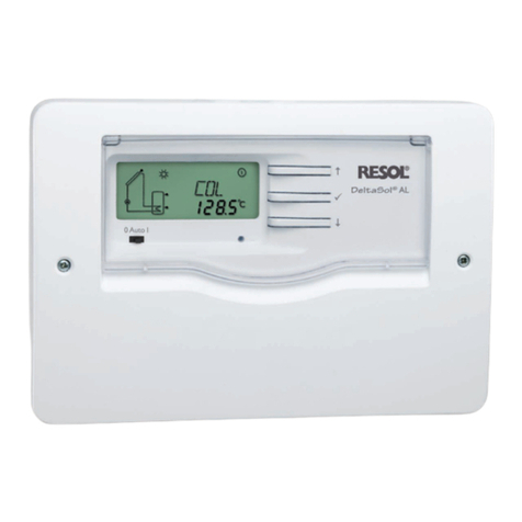
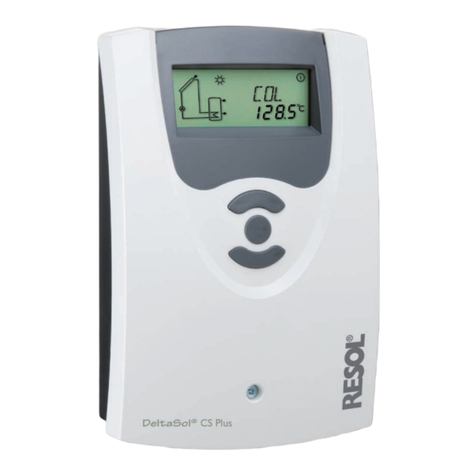
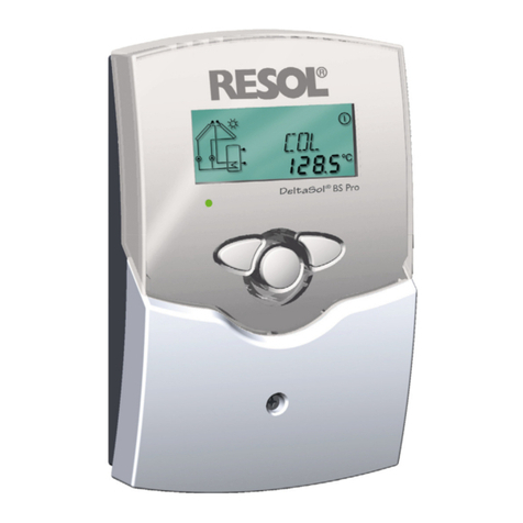
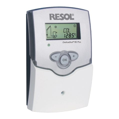
Resol DeltaSol C Plus Instruction manual

DeltaSol®C Plus
www.resol.de
Thank you for buying this RESOL product.
Please read this manual carefully, to get the best performance from this unit.
RESOL DeltaSol®C Plus
Mounting
Connection
Operation
Troubleshooting
Examples
Manual
B
*48003311*
48003311

© RESOL 14035 deltasol_c_plus.monen.indd
|2
DeltaSol®C Plus
Table of contents
Safety advice............................................................. 2
Overview of functions and technical data........ ......3
1. Installation.................................................... 4
1.1 Mounting........................................................................4
1.2 Electrical connection ..................................................4
1.2.1 Data communication / bus ........................................5
1.2.2-9 Terminal allocation Arrangements 1-9....................6
2. Operation and function............................. 10
2.1 Buttons for adjustment ........................................... 10
2.2 System-Monitoring display...................................... 10
2.2.1 Channel display ......................................................... 10
2.2.2 Toolbar........................................................................ 10
Information about the product
Proper usage
The solar controller is designed for use in solar thermal
and heating systems in compliance with the technical data
specified in these instructions.
Improper use excludes all liability claims.
Note
Strong electromagnetic fields can impair the
function of the controller.
ÎMake sure the controller as well as the
system are not exposed to strong electro-
magnetic fields.
Signal words describe the danger that may occur, when it
is not avoided.
WARNING means that injury, possibly life-threatening
injury, can occur.
ATTENTION means that damage to the appliance can
occur.
CE-Declaration of conformity
The product complies with the relevant
directives and is therefore labelled with the
CE mark. The Declaration of Conformity is
available upon request, please contact RESOL.
Disposal
Dispose of the packaging in an environmentally sound
manner.
Dispose of old appliances in an environmentally sound
manner. Upon request we will take back your old appliances
bought from us and guarantee an environmentally sound
disposal of the devices.
Subject to technical change. Errors excepted.
WARNING! Warnings are indicated with a
warning triangle!
They contain information on how
to avoid the danger described.
Safety advice
Please pay attention to:
- safety advice in order to avoid danger and damage to
people and property.
- the valid local standards, regulations and directives!
Target group
These instructions are exclusively addressed to authorised
skilled personnel.
Only qualified electricians should carry out electrical works.
Initial installation must be effected by qualified personnel
named by the manufacturer.
Description of symbols
2.2.3 System-Screen........................................................... 11
2.3 Flashing codes............................................................ 11
3. Commissioning .......................................... 12
4. Control parameters and and display
channels ...................................................... 13
4.1 Overview of channels.............................................. 13
4.1.1-7 Display channels........................................................ 15
4.1.6-22 Adjustment channels................................................ 16
5. Troubleshooting ......................................... 21
5.1 Various ........................................................................ 22
6. Accessory ................................................... 24
Imprint .................................................................... 24
Note
Notes are indicated with an information symbol.
© RESOL 14035 deltasol_c_plus.monen.indd
3 |
DeltaSol®C Plus
Functional overview
• System-Monitoring display
• up to 4 temperature sensors
Pt1000
• 2 semiconductor relays for
pump speed control
• 9 basic systems to choose from
• heat quantity measurement
• RESOL VBus®
• function control
• thermostat function
• thermal disinfection
• real time clock
• user-friendly operation
• easy-to-mount housing and
outstanding design
Technical data
Housing:
plastic, PC-ABS and PMMA
Protection type: IP 20 / DIN 40050
Ambient temp.: 0 ... 40 °C
Dimensions: 172 x 111 x 49 mm
Mounting:
wall mounting, mounting into patch
panels is possible
Display: system monitor for systems
visualisation,16-segment display,7-seg-
ment display, pictograms
Operation: 3 push buttons at the
front of the housing
Functions:Thermal disinfection,func-
tion control, operating hours counter,
tube collector function, pump speed
control, thermostat function and heat
quantity measurement
Inputs: for 4 temperature sensors
Pt1000
Outputs: 2 semiconductor relays
Bus: RESOL VBus®
Power supply:
100 ... 240V~
Total switching capacity:
2 (2) A (100 ... 240) V~
Switching capacity per relay:
semiconductor relay:
1 (1) A (100 ... 240)V~
!
111
30
62
172
49

© RESOL 14035 deltasol_c_plus.monen.indd
|4
DeltaSol®C Plus
1.2 Electrical connection The power supply to the controller must be carried out via
an external power switch (last step!) and the supply voltage
must be 100 ...240 V~(50 ...60 Hz). Flexible cables must be
attached to the housing with the enclosed strain relief and
the corresponding screws.
The controller is equipped with 2 relays to which loads
such as pumps, valves etc. can be connected:
• Relay 1
18 = conductor R1
17 = neutral conductor N
13 = ground terminal
• Relay 2
16 = conductor R2
15 = neutral conductor N
14 = ground terminal
The temperature sensors (S1 to S4) have to be con-
nected to the following terminals (either polarity):
1 / 2 = sensor 1 (e. g. sensor collector 1)
3 / 4 = sensor 2 (e. g. sensor store 1)
5 / 6 = sensor 3 (e. g. sensor collector 2)
7 / 8 = sensor 4 (e. g. sensor store TRF)
The mains connection is at the terminals:
19 = neutral conductor N
20 = conductor L
12 = ground terminal
mains terminals
fuse
load terminals
sensor terminals
ground terminals
VBus
910
1 (1) A (100 ... 240)V~
R1
R2
IP 20
T2A
100 ... 240 V~
50-60 Hz
VBus
display
push button
fuse
cable conduit with
strain relief
cover
1.1 Mounting
1. Installation
130
fastening
base
The unit must only be located in dry interior locations. It
is not suitable for installation in hazardous locations and
should not be placed close to any electromagnetic fields.The
controller must additionally be supplied from a double pole
switch with contact gap of at least 3 mm. Please pay atten-
tion to separate routing of sensor cables and mains cables.
1. Unscrew the cross-head screw from the cover and re-
move it along with the cover from the housing.
2. Mark the upper fastening point on the wall and drill and
fasten the enclosed wall plug and screw leaving the head
protruding.
3. Hang the housing from the upper fastening point and
mark the lower fastening point through the hole in the
terminal box (centres 130 mm). Drill and insert the lower
wall plug.
4. Hang the housing from the upper fastening point and
tighten lower fastening screw.
fastening
Electrostatic discharge can cause damage of electronic
components!
High-voltage components!
WARNING!
ÎAlways disconnect the con-
troller from power supply
before opening the housing!
Note
The relays are semiconductor relays for pump
speed control.
The minimum pump speed must be set to 100%
when auxiliary relays or valves are connected.

© RESOL 14035 deltasol_c_plus.monen.indd
5 |
DeltaSol®C Plus
S1
S2
S4 / TRF
1.2.2 Terminal allocation Arr 1 Standard solar system with 1 store, 1 pump and 3
sensors. Sensor S4 / TRF can optionnally be used for heat
quantity measurement.
R1
ARR 1
S3
1.2.1 Data communication / bus
The controller is equipped with the RESOL VBus®for
data transfer with and energy supply to external modules.
The connection is carried out at the two terminals 9 and
10 marked “VBus®“ (either polarity). One or more RESOL
VBus®modules can be connected via this data bus:
•GA3 large display, SD3 smart display
•DL2 datalogger
•VBus®/USB or VBus®/LAN interface adapter
•VBus®/PWM interface adapter
•AM1 alarm module
•WMZ calorimeter module
By means of a DL2 datalogger or an interface adapter, the
controller can be connected to a PC or a computer net-
work.With the RESOL ServiceCenter Software (RSC) the
controller measurements can be read out, processed and
visualised.The software allows easy function control of the
system. For the remote parametrisation of the controller, a
special software tool will be available for download, soon.
VBus
910
1 (1) A (100 ... 240) V~
R1
R2
IP 20
T2A
100 ... 240 V~
50-60 Hz
Symbol Description
S1 collector sensor
S2 store sensor base
S3 store sensor top /
(optional)
S4 / TRF sensor for heat quantity
measurement (optional)
R1 solar pump

© RESOL 14035 deltasol_c_plus.monen.indd
|6
DeltaSol®C Plus
R2
S1
S2
R1 S3
S4 / TRF
1.2.4 Terminal allocation Arr 3 Solar system and after-heating with 1 store, 3 sensors
and after-heating. Sensor S4 / TRF can optionnally be used
for heat quantity measurement.
ARR 3
S1
S3
S4
R1
R2
S2
1.2.3 Terminal allocation Arr 2 Solar system and heat exchange to existant store
with 2 stores, 4 sensors and 2 pumps.
ARR 2
store 1
store 2
Symbol Description
S1 collector sensor
S2 store base sensor
S3 store top sensor
S4 store sensor 2
R1 solar pump
R2 pump for
heat exchange
Symbol Description
S1 collector sensor
S2 store sensor base
S3 store sensor top
S4 / TRF Sensor for heat quantity
measurement (optional)
R1 solar pump
R2 charging pump
after-heating

© RESOL 14035 deltasol_c_plus.monen.indd
7 |
DeltaSol®C Plus
1.2.5 Terminal allocation Arr 4
1.2.6 Terminal allocation Arr 5
S2
R1
S3
R2
S1
Solar system and vertical store charging with 1 store,
3 sensors, 1 solar pump and 3-port valve for vertical store
charging. Sensor S4 / TRF can optionnally be used for heat
quantity measurement.
2-store solar system with valve control with 2 stores,
3 sensors, 1 solar pump and 1 3-port valve. Sensor S4 / TRF
can optionnally be used for heat quantity measurement.
R2
S4 / TRF
S1
R1
S2 S3
S4 / TRF
ARR 4
ARR 5
store 1 store 2
Symbol Description
S1 collector sensor
S2 store sensor base
S3 store sensor top
S4 / TRF sensor for heat quantity
measurement (optional)
R1 solar pump
R2 3-port valve
Symbol Description
S1 collector sensor
S2 store sensor 1
S3 store sensor 2
S4 / TRF sensor for heat quantity
measurement (optional)
R1 solar pump
R2 3-port valve

© RESOL 14035 deltasol_c_plus.monen.indd
|8
DeltaSol®C Plus
1.2.7 Terminal allocation Arr 7 Solar system with east-/west collectors, 1 store, 3
sensors and 2 solar pumps.
R1 R2
S1
S2
S3
ARR 7
S1
S2 S3
R1 R2
1.2.6 Terminal allocation Arr 6 2-store solar system with pump control with 2 stores,
3 sensors and 2 solar pumps.
ARR 6
store 1 store 2
S4
Symbol Description
S1 collector sensor
S2 store sensor 1
S3 store sensor 2
S4 sensor (optional)
R1 solar pump store 1
R2 solar pump store 2
Symbol Description
S1 collector sensor 1
S2 store sensor
S3 collector sensor 2
S4 sensor (optional)
R1 solar pump collector 1
R2 solar pump collector 2

© RESOL 14035 deltasol_c_plus.monen.indd
9 |
DeltaSol®C Plus
S1
S3
S2
S4
R2
R1
S1
S4
S2
S3
R1
R2
1.2.8 Terminal allocation Arr 8
1.2.9 Terminal allocation Arr 9
Solar system with after-heating with solid fuel boiler
with 1 store 4 sensors, 1 solar pump and 1 pump for after-
heating.
Solar system and heating circuit return preheating with
1 store, 4 sensors,1 solar pump and 1 3-port valve for heating
circuit return preheating.
ARR 8
ARR 9
Symbol Description
S1 collector sensor
S2 store sensor base
S3 store sensor top
S4 sensor for solid fuel boiler
R1 solar pump
R2 pump for solid fuel boiler
Symbol Description
S1 collector sensor
S2 store sensor base
S3 store sensor top
S4 heating circuit - return
R1 solar pump
R2 3-port valve

© RESOL 14035 deltasol_c_plus.monen.indd
|10
DeltaSol®C Plus
The system monitoring display consists of 3 ranges: The
channel display, the toolbar and the system-screen
(active arrangement).
The channel display consists of 2 lines.The upper line is an
alpha-numeric 16-segment display (text display) for display-
ing channel names and menu items. In the lower 7-segment
display, the channel values and the adjustment parameters
are displayed.
Temperatures and temperature differences are indicated
in or .
2.2.1 Channel display
channel display
2.2.2 Toolbar
The additional symbols in the toolbar indicate the actual
system status.
toolbar
2.2 System-Monitoring display
!
Monitoring-Display
symbol normal flashing
relay 1 active
relay 2 active
store maximum limitation
active / maximum store
temperature exceeded
collector cooling function active
recooling function active
antifreeze function active
collector minimum limitation
active
antifreeze function active
collector emergency shut-
down active or store emer-
gency shutdown active
+ sensor fault
+ manual mode
change of adjustment channel
SET-mode
1
2
3
backwards
SET
(selection/adjust-
ment mode)
2. Operation and function
2.1 Buttons for adjustment
Connect the controller to the mains. The controller is in
an initialisation phase. After this phase, the controller is in
automatic operation with factory settings.
The controller is operated via the 3 push buttons below the
display.The forward-button (1) is used for scrolling forward
through the menu or to increase the adjustment values.The
backward-button (2) is similarly used for scrolling backwards
and reducing values.
In order to access the adjustment mode, scroll down in the
display menu and press the forward button (1) for approx.
2 seconds after you have reached the last display item. If
an adjustment value is shown on the display, the icon
is displayed. Now, you can access the adjustment mode by
using button 3.
— Press buttons 1 and 2 in order to select a channel
— Briefly press button 3, appears (flashing) (
-mode)
— adjust the requested value by pressing the buttons 1 and 2
— Briefly press button 3, so that permanently appears,
the adjusted value will be saved.
forwards

© RESOL 14035 deltasol_c_plus.monen.indd
11 |
DeltaSol®C Plus
The system screen (active arrangement) shows the scheme
which has been selected. The screen consists of several
system component symbols, which are - depending on the
current status of the system - either flashing, permanently
shown or „hidden“.
sensor
collector
pumps
heating circuit
sensor
additional symbol
operation of the
burner
valve
store
store heat exchanger store 2 or afterheating (with
additional symbol)
sensor store bottom
valve
collectors
with collector sensor
pump
3-port valve
the flow direction or the current
switching position is shown
heating circuit
store 1 and 2
with heat exchanger
after-heating
with burner symbol
temperature sensor
2.2.3 System-Screen
System screen
2.3 Flashing codes •Pump symbols are flashing during the initialisation phase
•Sensor symbols are flashing when the corresponding sen-
sor display channel is selected.
•Sensor symbols are flashing in the case of a sensor fault
•Burner symbol is flashing when the after-heating is active.

© RESOL 14035 deltasol_c_plus.monen.indd
|12
DeltaSol®C Plus
3. Commissioning
When the controller is commissionend for the first time, the arrangement has to be
selected first 1. Switch on power supply.After initialisation, the controller
is in the automatic mode with typical settings. The pre-
programmed system scheme is Arr 1.
2. Adjust the actual clock time in the TIME channel. Pressing
the -key for 2 seconds will display the hours, pressing
the button again will display the minutes (flashing).Time
can be adjusted using buttons 1 and 2. Save the changes
by pressing the -key.
3. - Select the ARR channel
- Change into the -mode (see 2.1)
- Selct the system arrangement via the ARR number
- Save adjustments by pressing the -key
Now the controller is ready for operation with typical set-
tings to suit that system and normally the factory settings
will give close to optimum operation.
Overview of arrangements:
ARR 1 : standard solar thermal system
ARR 2 : solar thermal system with heat exchange
ARR 3 : solar thermal system with after-heating
ARR 4 : solar thermal system with vertical store charging
ARR 5 : 2-store solar thermal system with valve control
ARR 6 : 2-store solar thermal system with pump control
ARR 7 : solar thermal system with 2 collectors and 1 store
ARR 8 : solar thermal system with after-heating with solid
fuel boiler
ARR 9 : solar thermal system heating circuit return pre-
heating
ARR 1 ARR 2
ARR 3 ARR 4
ARR 5 ARR 6
ARR 7 ARR 8
ARR 9
1
2
3
backwards
SET
(selection /
adjustment mode)
forwards

© RESOL 14035 deltasol_c_plus.monen.indd
13 |
DeltaSol®C Plus
4. Control parameters and display channels
4.1 Overview of channels
Legend:
x
Corresponding channel is available.
x*
Corresponding channel is available when the corresponding
option is enabled
Only if the option heat quantity measurement is activated
(OHQM), will the corresponding channel be available.
MEDT
Only if an antifreeze (MEDT) other than water or Tyfo-
cor LS / G-LS (MEDT 0 or 3) is used, will the channel
antifreeze concentration (MED%) be displayed.The adjust-
ment of the antifreeze concentration has only to be carried
out when an antifreeze is used in the solar circuit.
Only if the option heat quantity measurement is deactivated
(OHQM), will the corresponding channel be available.
channel ARR descritption page
123456789
COL x x x x x x x x temperature collector 1 15
COL 1 x temperature collector 1 15
TST x x temperature store 1 15
TSTU x x x x temperature store 1 base 15
TST1 x x x temperature store 1 base 15
TSTO x x x x x temperature store 1 top 15
TST2 x x x temperature store 2 base 15
TFSK x temperature solid fuel boiler 15
TREC x temperature heating circuit 15
COL2 x temperature collector 2 15
S3 x temperature sensor 3 15
TRF temperature return temperature sensor 15
S4 x x temperature sensor 4 15
n % x x x x speed relay 1 15
n1 % x x x x x speed relay 1 15
n2 % x x x x speed relay 2 15
hP x x x x operating hours relay 1 16
h P1 x x x x x operating hours relay 1 16
h P2 x x x x x operating hours relay 2 16
CDIS x* Countdown of monitoring period 16
SDIS x* Starting time display 16
DDIS x* Heating period display 16
kWh heat quantity kWh 16
MWh heat quantity MWh 16
TIME x time 15
ARR 1-9 arrangement 12
DT O x x x x x x switch-on temperature difference 17
DT1O x x x switch-on temperature difference 1 17
DT F x x x x x x switch-off temperature difference 1 17
DT S x x x x x x set temperature difference 17
RIS x x x x x x rise 17
DT1F x x x switch-off temperature difference 17
RIS1 x x x rise 1 17
DT1S x x x set temperature difference 1 17
S MX x x x x x x maximum temperature store 1 17
S1 MX x x x maximum temperature store 1 17
DT2O x x x switch-off temperature difference 2 17
DT2F x x x switch-off temperature difference 2 17
DT2S x x x set temperature difference 2 17
RIS2 x x x rise 2 17
S2MX x x x maximum temperature store 2 17
Note
Only if temperature sensors are connected, will
S3 and S4 be displayed.

© RESOL 14035 deltasol_c_plus.monen.indd
|14
DeltaSol®C Plus
channel ARR description page
123456789
EM x x x x x x x x emergency temperature collector 1 18
EM1 x emergency temperature collector 1 18
OCX x x x x x x x x option collector cooling collector 1 18
OCX1 x option collector cooling collector 1 18
CMX x* x* x* x* x* x* x* x* maximum temperature collector 1 18
CMX1 x* maximum temperature collector 1 18
OCN x x x x x x x x option minimum limitation collector 1 18
OCN1 x option minimum limitation collector 1 18
CMN x* x* x* x* x* x* x* x* minimum temperature collector 1 18
CMN1 x* minimum temperature collector 1 18
OKF x x x x x x x x option frost protection collector 1 18
OKF1 x option frost protection collector 1 18
CFR x* x* x* x* x* x* x* x* frost protection temperature collector 1 18
CFR1 x* frost protection temperature collector 1 18
EM2 x emergency temperature collector 2 18
OCX2 x option collector cooling collector 2 18
CMX2 x* maximum temperature collector 2 18
OCN2 x option minimum limitation collector 2 18
CMN2 x* minimum temperature collector 2 18
OCF2 x option frost protection collector 2 18
CFR2 x* frost protection temperature collector 2 18
PRIO x x x priority 19
tST x x x loading break time 19
tCIRC x x x oscillating loading time 19
OREC x x x x x x x x x option recooling 19
O TC x x x x x x x x x option tube collector 19
DT3O x x switch-on temperature difference 3 17
DT3F x x switch-off temperature difference 3 17
DT3S x x set temperature DT3 17
RIS3 x x rise DT3 17
MX3O x x switch-on threshold for maximum temp. 17
MX3F x x switch-off threshold for maximum temp. 17
MN3O x x switch-on threshold for minimum temp. 17
MN3F x x switch-off threshold for minimum temp.. 17
AH O x switch-on temperature thermostat 1 20
AH F x switch-off temperature thermostat 1 20
t1 O x switch-on time 1 thermostat 20
t1 F x switch-off time 1 thermostat 20
t2 O x switch-on time 2 thermostat 20
t2 F x switch-off time 2 thermostat 20
t3 O x switch-on time 3 thermostat 20
t3 F x switch-off time 3 thermostat 20
OtD x Option thermal disinfection 16
PDIS x* Monitoring period 20
DDIS x* Heating period 20
TDIS x* Disinfection temperature 16
SDIS x* Starting time 16
CDIS x* Countdown of monitoring period 16
n2MN x x x x minimum speed relay 2 20
HND1 x x x x x x x x x manual operation relay 1 20
HND2 x x x x x x x x x manual operation relay 2 20
LANG x x x x x x x x x Language 20
PROG XX.XX program number
VERS X.XX version number

© RESOL 14035 deltasol_c_plus.monen.indd
15 |
DeltaSol®C Plus
4.1.1 Collector temperatures
Displays the current collector temperature.
•COL : collector temperature (1-collector system)
•COL1: collector temperature 1
•COL2: collector temperature 2
COL, COL1, COL2:
Collector temperatures
display range: -40 ...+250 °C
4.1.2 Store temperatures
Displays the current store temperature.
•TST : store temperature (1-store system)
•TSTL : store temperature base
• TSTU : store temperaturer top
•TST1 : temperature store 1
• TST2 : temperature store 2
TST,TSTL,TSTU,
TST1,TST2:
Store temperatures
Display range: -40 ...+250 °C
4.1.3 Sensors 3 and 4
Display of the current temperature at the corresponding
additional sensor (without control function).
•S3 : temperature sensor 3
•S4 : temperature sensor 4
S3, S4:
Sensor temperatures
Display range: -40 ...+250 °C
4.1.5 Pump speed
Display of the current speed of the corresponding pump.
•n % : actual pump speed (1-pump system)
•n1 % : actual speed pump 1
•n2 % : actual speed pump 2
n %, n1 %, n2 %:
Current pump speed
Display range: 30 ...100 %
4.1.6 Time
In this channel the current time is indicated.
Press button for 2 seconds, the hours will then be
displayed. Press the button again, the minutes will then be
displayed (flashing).The time can be set using buttons 1 and
2 and saved by pressing the button.
4.1.4 Other temperatures
Display of the current temperature at the corresponding
sensor.
•TSFB : temperature solid fuel boiler
•TREC : temperature heating return
•TRF : temperature return
TSFB,TREC,TRF:
Other measured temperatures
Display range: -40 ...+250 °C
4.1.7 Operating hours counter
The operating hours counter accumulates the solar operat-
ing hours of the respective relay (h P / h P1 / h P2). Full
hours are displayed.
The accumulated operating hours can be set back to zero.
As soon as one operating hours channel is selected, the sym-
bol is displayed. Press the SET (3) button for approx. 2
seconds in order to access the RESET-mode of the counter.
The display symbol will flash and the operating hours
will be set to 0. Confirm the reset with the button in
order to finish the reset.
In order to interrupt the RESET-process, do not press a
button for about 5 seconds. The display returns to the
display mode.
h P / h P1 /h P2:
Operating hours counter
Display channel
Note
Only if temperature sensors are connected,
will S3 and S4 be displayed

© RESOL 14035 deltasol_c_plus.monen.indd
|16
DeltaSol®C Plus
4.1.8 Heat quantity measurement
OHQM: Heat quantity
measurement
Adjustment range: OFF...ON-
Factory setting: OFF
Heat quantity measurement is possible in systems (ARR) 1,
3, 4 and 5 if a flowmeter is used. For this purpose, the heat
quantity measurement option OHQM has to be enabled.
The flow rate should be read from the flowmeter (l/min)
and has to be adjusted in the channel FMAX. Antifreeze
type and concentration of the heat transfer medium have
to be adjusted in the channels MEDT and MED%.
Antifreeze type:
0 : water
1 : propylene glycol
2 : ethylene glycol
3 : Tyfocor®LS / G-LS
FMAX: Flow rate in l/min
Adjustment range 0...20,
in 0.1 steps
Factory setting: 6,0
kWh/MWh:Heat quantity
kWh / MWh
Display channel
MEDT: Antifreeze type
Adjustment range: 0...3
Factory setting: 1
MED%: Antifreeze concen-
tration in (Vol-) %
When MEDT 0 or 3 is used,
the parameter MED% is
‚hidden‘.
Adjustment range: 20...70
Factory setting: 45
The flow rate as well as the reference sensors S1 (flow) and
S4 (return) are used for calculating the heat quantity sup-
plied. It is shown in kWh in the channel kWh uand in MWh
in the channel MWh .The overall heat quantity results from
the sum of both values.
The accumulated operating hours can be set back to zero.
As soon as one of the display channels of the heat quantity
is selected, the symbol is displayed. Press the SET (3)
button for approx. 2 seconds in order to access the RESET-
mode of the counter.The display symbol will flash and
the heat quantity value will be set to 0. Confirm the reset
with the button in order to finish the reset.
In order to interrupt the RESET process, no button should
be pressed for about 5 seconds.The display returns to the
display mode.
CDIS
Countdown of monitoring
period
Display range:
0 ... 30:0 ... 24 (dd:hh)
SDIS
Starting time display
Display range:
00:00 ... 24:00 (hh:mm)
DDIS
Heating period display
Display range:
00:00 ... 24:00 (hh:mm)
If the thermal disinfection option (OtD) is activated and
the heating period is in progress, the remaining time of the
heating period is displayed (in hours and minutes) in this
channel, counting backwards.
If the thermal disinfection option (OtD) is activated and
a starting delay time has been adjusted, the adjusted delay
time is displayed (flashing) in this channel.
If the thermal disinfection option (OtD) is activated and
the monitoring period is in progress, the remaining moni-
toring time will be displayed as CDIS (in days and hours)
and counted backwards.
4.1.7 Thermal disinfection

© RESOL 14035 deltasol_c_plus.monen.indd
17 |
DeltaSol®C Plus
4.1.9 ∆T-control
DT O / DT1O / DT2O /
DT3O:
Switch-on temperature difference
Adjustment range: 1,0 ... 20,0 K
Factory setting: 6.0
DT F / DT1F / DT2F / DT3F:
Switch-off temperature
difference
Adjustment range: 0,5 ... 19,5 K
Factory setting: 4.0 K
4.1.10 Maximum store temperature If the adjusted maximum temperature is exceeded, the store
will no longer be loaded in order to avoid damage caused by
overheating. If the maximum store temperature is exceeded,
(flashing) is shown on the display.
S MX / S1MX /S2MX:
Maximum store temperature
Adjustment range: 2 ... 95 °C
Factory setting: 60 °C
DT S / DT1S / DT2S /
DT3S:
Set temperature difference
Adjustment range: 1,5 ... 30,0 K
Factory setting: 10.0
RIS / RIS1 / RIS2 / RIS3:
Rise
Adjustment range: 1 ... 20 K
Factory setting: 2 K
This function is a standard differential control. If the switch-
on differential is reached (DT O /DT1O /DT2O) the
pump is operated. The pump runs at 100% speed for 10
seconds. After this period, the pump runs at minimum
pump speed (nMN = 30 %) gefahren. f the temperature
difference reaches the adjusted set value (DT S /DT1S
/DT2S / DT3S), spump speed will increase by one step
(10 %). If the difference increases by 2 K (RIS / RIS1 /
RIS2 / RIS3) pump speed will increase by 10 % respec-
tively until the maximum pump speed of 100 % is reached.
The response of the controller can be adapted via the
parameter „Rise“ If the temperature difference falls be-
low the adjusted switch-off temperature difference
(DT F /DT1F /DT2F) the controller switches off.
DT O and DT S are blocked against each other. DT S must
be at least 0,5 K higher than DT O.
4.1.11 ∆T control (solid fuel boiler and heat exchange)
The controller is equipped with an independent tempera-
ture differential control function for which minimum and
maximum temperature limations as well as the correspon-
ding switch-on and -off temperatures can be separately
adjusted. For ARR = 2 and 8 only (solid fuel boiler and heat
exchange control).
Maximum temperature limitation
MX3O / MX3F:
Maximum temperature
limitation
Adjustment range: 0,0 ... 95,0 °C
Factory setting:
MX3E 60,0 °C
MX3A 58,0 °C
If the adjustet value MX3O is exceeded, relay 2 will be
switched off. If the temperature falls below the value MX3F,
the relay will be energised.
Reference sensors:
S3 for ARR 8 (TSTU)
S4 for ARR 2 (TST2).
If the temperature falls below MN3O, relay 2 will be swit-
ched off. If the value MN3F is exceeded, the relay will be
energised.
Reference sensors:
S4 for ARR 8 (TSFB)
S3 for ARR 2 (TSTU).
The switch on- and switch off temperature differences
DT3O and DT3F also apply to the maximum- and mini-
mum temperature limitation.
Minimum temperature limitation
MN3O / MN3F:
Minimum temperature
limitation
Adjustment range: 0,0 ... 90,0 °C
Factory setting:
ARR = 2
MN3O 5,0 °C
MN3F 10,0 °C
ARR = 8
MN3O 60,0 °C
MN3F 65,0 °C
Note
The controller is equipped with a store emer-
gency shutdown function, which prevents the
store from being loaded when the store tem-
perature exceeds 95°C.
Note
Switch-on temperature difference must be at
least 1 K higher than the switch-off temperature
difference.

© RESOL 14035 deltasol_c_plus.monen.indd
|18
DeltaSol®C Plus
4.1.16 Store sequence control
Corresponding adjustment values:
Factory setting Adjustment range
Priority [PRIO] (1 / ARR 5,6) (2 / ARR 4) 0-2
Loading break time [tSP] 2 min. 1-30 min.
Oscillating loading time [tUMW] 15 min. 1-30 min.
CMN / CMN1 / CMN2:
Collector minimum
temperature
Adjustment range: 10 ... 90 °C
Factory setting: 10 °C
CMX / CMX1 /CMX2:
Maximum collector
temperature
Adjustment range: 100... 190 °C
Factory setting: 120 °C
4.1.13 System cooling When the adjusted maximum store temperature is reached,
the system stagnates. If the collector temperature increases
to the adjusted maximum collector temperature (CMX
/ CMX1 /CMX2) the solar pump is activated until the
collector temperature falls below the maximum collector
temperature. The store temperature may increase (sub-
ordinate active maximum store temperature), but only up
to 95 °C (emergency shutdown of the store). If the store
temperature is higher than the maximum store temperature
(S MX / S1MX / S2MX) and if the collector temperature
is at least 5 K below the store temperature, the solar system
remains activated until the store is cooled down below the
adjusted maximum temperature (S MX / S1MX / S2MX)
via the collector and the pipework (only if the OREC
function is activated).
OCX / OCX1 /OCX2:
System cooling option
Adjustment range: OFF ... ON
Factory setting: OFF
4.1.14 Collector minimum limitation option
OCN / OCN1 /OCN2:
Collector minimum limitation
Adjustment range: OFF / ON
Factory setting: OFF
The minimum collector temperature is the minimum tem-
perature which must be exceeded for the solar pump (R1
/ R2) to switch on.The minimum temperature prevents the
pump from being switched on too often at low collector
temperatures. If the temperature falls below the minimum
temperature, (flashing) is shown on the display.
CFR / CFR1 / CFR2:
Frost protection temperature
Adjustment range: -10 ...10 °C
Factory setting: 4,0 °C
4.1.15 Frost protection function option
OCF / OCF1 /OCF2:
Frost protection function
Adjustment range: OFF / ON
Factory setting: OFF
The antifreeze function activates the loading circuit between
the collector and the store when the temperature falls be-
low the adjusted antifreeze temperature. This will protect
the fluid against freezing or coagulating. If the adjusted anti-
freeze temperature is exceeded by 1 °C, the loading circuit
will be deactivated.
4.1.12 Collector-limit temperature
Collector emergency shutdown
If the adjusted collector emergency shutdown temperature
(NOT / NOT1 / NOT2) is exceeded, the controller will
switch off the solar pump (R1 / R2) in order to protect the
system against overheating (collector emergency shutdown).
The factoring setting is 140 °C but it can be changed within
the adjustment range of 110 ...200 °C. If the temperature is
exceeded, (flashing) is shown on the display.
EM / EM1 / EM2:
Collector emergeny shutdown
temperature
Adjustment range: 110 ... 200 °C
Factory setting: 140 °C
If the system cooling function is enabled, (flashing) is
shown on the display. Due to the cooling function, the sys-
tem will have a longer operation time on hot summer days
and guarantees thermal relief of the collector field and the
heat transfer fluid.
Note
Since this function uses the limited heat quantity
of the store, the antifreeze function should be
used in regions with few days of temperatures
around the freezing point.

© RESOL 14035 deltasol_c_plus.monen.indd
19 |
DeltaSol®C Plus
When the priority store cannot be loaded, the subordinate
stores are checked.If a subordinate store can be loaded,it will
be loaded for the “oscillating loading time“ (“t-circ.“). After
this period of time, the loading process stops.The controller
monitors the increase in collector temperature.If it increases
by the“collector rise temperature (∆T-col 2 K, software value)
within the loading break time (t-st) the elapsed break time is set
to 0.The break time starts again.the switch-on condition of the
priority store is not fulfilled, loading of the subordinate store
will be continued. If the priority store reaches its maximum
temperature, oscillating loading will not be carried out.
Loading break time / store sequence control: /
collector rise temperature:
The DeltaSol®C Plus priority logic: The options and parameters mentioned above are used in
multi-store systems only (system ARR = 4, 5, 6). If priority
is set to 0, the stores with a temperature difference to the
collector are loaded in numerical order (store 1 or 2;
ARR= 4, 5). Basically, only one store can be loaded at a time.
In ARR the stores can be loaded in parallel.
Priority:
4.1.17 Recooling function If the adjusted maximum store temperature (S MX, S1MX,
S2MX) is reached, the controller keeps the solar pump
running in order to prevent the collector from being over-
heated.The store temperature may increase, but only up to
95 °C (emergency shutdown of the store).
The solar pump is switched on as soon as possible (depend-
ing on weather conditions). It is switched off when the store
is cooled down to the adjusted maximum temperature via
the collector and the pipework.
OREC:
Recooling option
Adjustment range: OFF ...ON
Factory setting: OFF
4.1.18 Tube collector function
If the controller detects an increase in collector temperature by
2 K compared to the previously stored collector temperature,
the solar pump will be switched-on for about 30 seconds in
order to detect the fluid temperature.After this, the current
collector temperature will be saved as a new reference value. If
the measured temperature (new reference value) is exceeded
by 2 K,the solar pump will run for 30 seconds. If the switch-on
difference between the collector and the store is exceeded
during the runtime of the solar pump or the standstill of the
system, the controller will automatically switch to solar loading.
If the collector temperature deacreases by 2 K during stand-
still, the switch-on value for the tube collector function will
be recalculated.
O TC:
Tube collector function
Adjustment range: OFF ...ON
Factory setting: OFF
The thermostat function works independently from the
solar operation and can be used for using surplus energy
or for after-heating.
• AH O < AH F
thermostat function for after-heating
• AH O > AH F
thermostat function for using surplus energy
When the 2nd relay output is active, is displayed
4.1.19 Thermostat function (ARR = 3)
afterheating use of surplus heat
AH O:
Thermostat switch-on temp.
Adjustment range:
0,0 ...95,0 °C
Factory setting: 40,0 °C
AH F:
Thermostat switch-off temp.
Adjustment range:
0,0 ...95,0 °C
Factory setting: 45,0 °C

© RESOL 14035 deltasol_c_plus.monen.indd
|20
DeltaSol®C Plus
t1 O t2 O, t3 O:
Thermostat switch-on time
Adjustment range:
00:00 ...23:45
Factory setting: 00:00
t1 F, t2 F, t3 F:
Thermostat switch-off time
Adjustment range:
00:00 ...23:45
Factory setting: 00:00
In order to block the thermostat function for a certain
period of time, there are 3 time frames t1 ...t3. If the func-
tion should be activated only between e.g. 6:00 and 9:00, set
t1 O to 6:00 and t1 F to 09:00.The thermostat function is
continuously activated (factory setting).
If all time frames are set to 00:00, the thermostat function
is continuously activated (factory setting).
TDIS
Disinfection temperature
Adjustment range: 0 ... 95 °C
in steps of 1 K
Factory setting: 60 °C
DDIS
Heating period
Adjustment range:
00:00 ... 23:59 (hh:mm)
Factory setting: 01:00
PDIS:
Monitoring period
Adjustment range:
0 ... 30:0 ... 24 h (dd:hh)
Factory setting: 01:00
OtD:
Thermal disinfection function
Adjustment range: ON / OFF
Factory setting: OFF
Thermal disinfection
This function helps to contain the spread of Legionella in
DHW stores by systematically activating the afterheating.
For thermal disinfection, the temperature at the allocated
sensor has to be monitored.This protection is ensured when,
during the monitoring period, the disinfection temperature
is continuously exceeded for the entire disinfection period.
The monitoring period starts as soon as the temperature at
the allocated sensor falls below the disinfection temperature.
When the monitoring period ends, the allocated reference
relay activates the afterheating.The disinfection period starts,
if the temperature at the allocated sensor exceeds the disin-
fection temperature.
Thermal disinfection can only be completed when the dis-
infection temperature is exceeded for the duration of the
disinfection period without any interruption.
Thermal disinfection with starting delay
SDIS
Starting time
Adjustment range:
00:00 ... 24:00 (o‘clock)
Factory setting: 00:00
If the starting delay option is activated, a starting time for
the thermal disinfection with starting delay can be adjusted.
The activation of the afterheating is then delayed until that
starting time after the monitoring period has ended.
If the monitoring period ends,for example,at 12:00 o‘clock,
and the starting time has been set to 18:00, the reference
relay will be energised with a delay of 6 hours at 18:00
instead of 12:00 o‘clock.
Note:
If the thermal disinfection option is activated,
the display channelsTDIS, CDIS, SDIS,and DDIS
will be displayed.
Table of contents
Other Resol Controllers manuals

Resol
Resol DeltaSol ES User manual

Resol
Resol DeltaSol AL Service manual

Resol
Resol DeltaSol MX Owner's manual

Resol
Resol DeltaSol BX+ V2 Quick start guide

Resol
Resol DeltaSol C2 User manual

Resol
Resol HC User manual

Resol
Resol VA20 User manual

Resol
Resol DeltaSol AL EHE User manual

Resol
Resol DeltaSol ES User manual

Resol
Resol DeltaSol SLL Owner's manual

Resol
Resol DeltaSol BS User manual

Resol
Resol DeltaTherm PV User manual

Resol
Resol DeltaSol CS Plus User manual

Resol
Resol FriWa User manual

Resol
Resol DeltaSol BX L User manual

Resol
Resol DeltaSol SL User manual

Resol
Resol DeltaSol E User manual

Resol
Resol DeltaSol M User manual

Resol
Resol DeltaSol BX L User manual

Resol
Resol DeltaSol E User manual