Epever EG1200CU User manual

user manual
Digital AC/DC Power
Supply
EG1200CU
40~60V 0~20A
USER MANUAL


CONTENTS
Chapter I ATTENTIONS ......................................................................... 1
Chapter II OVERVIEW ........................................................................... 3
Chapter III TECHNICAL SPECIFICATIONS................................................ 5
Chapter IV OPERATION MODE ............................................................. 7
Section I Power Mode Introduction ......................................................7
Section II Charging Mode Introduction..................................................8
Section III Multi-machine Operation ................................................... 10
Chapter V OPERATION INTERFACE ..................................................... 12
Section I Panel Shows..........................................................................12
Section II Human-Machine Interface...................................................13
Section III Display Operation ...............................................................15
Chapter VI PROTECTION FUNCTION ................................................... 20
Chapter VII SIMPLE TROUBLESHOOTING GUIDE ................................. 23
Chapter VIII MAINTENANCE PROCEDURE ........................................... 25
Chapter IX OVERALL DIMENSIONS ..................................................... 26
All rights reserved. The contents in this document are subject to change without notice.

Chapter I ATTENTIONS
Thank you very much for selecting our product! This manual offers
important information and suggestions with respect to installation, use and
troubleshooting, etc. Please read this manual carefully before using the
product and pay attention to the safety recommendations.
This manual contains important safety, function, installation and operating
instructions for the digital power supply.
The following symbols are used throughout this manual to indicate
potentially dangerous conditions or mark important safety instructions.
Please take care of it when meeting these symbols.
CAUTION: Indicates a critical procedure for safe and
proper operation of the digital power supply.
NOTE: Indicates a procedure or function that is
important for the safe and correct operation for the
digital power supply.
Safety Information
Read all of the instructions and cautions carefully before installation.
Reversing the load polarity is very easy to damage the equipment or
come into the unpredictable dangers.
Do not disassemble the product in order to avoid personal injury.
-1-

There is non-security voltage inside of the power supply. Please call
the professionals in our company if you need repair.
Do not install, replace parts or perform any unauthorized modifications
on the instrument.
Turn off the power before moving the working power supply.
In order to avoid the risk of loose connection, please ensure that all
connections are tight.
Do not put heavy things on the power supply to avoid failures.
-2-

Chapter II OVERVIEW
EG1200CU--Digital switching power supply is a new generation of full
digital isolate switching power supply which is designed with the
technology of advanced active power factor correction and resonant
soft-switching. The power supply has a wide range of AC input and an
adjustable DC output. It has high power factor, high precision regulating,
small size, high efficiency and other characteristics. The power supply is
developed based on the industrial communication standard of
YD/T731-2008 and realizes the full digital control based on the DSP
(Digital Signal Processor) chip. Besides the power mode which can
continuously output the constant-voltage or constant-current, it is also
added the complete battery charging management mode. It can be used as
the constant-voltage constant-current or battery charging power supply in
order to meet the different applications.
The input port can beconnected to mains or the output of oil-machine. The
product can form a hybrid power system with the other products.
FEATURES
The product adopts the advanced control algorithms and realizes the
full digital control based on the DSP (Digital Signal Processor) chip.
Using the isolated Hall components to assure the power supply a
strong anti-interference ability.
The power supply is suitable for the situation of volatile AC voltage
-3-

whose range from 176 to 265V.
Output voltage can be adjusted continuously from 40 to 60V. The
minimum adjustable voltage is 0.1V.
Output current can be adjusted continuously from 0 to 20.5A. The
minimum adjustable current is 0.1A.
The output charging current can be set as constant according to the
actual battery’s AH.
Without reducing rated power at the ambient temperature of 55℃.
The power supply has a complete three-stages charging mode for bulk
charge, equalizing charge and float charge.
Multiple products with the same type can be connected in parallel or
series and ‘Hot-Swappable’ application can be realized.
HMI uses the LED to display rich content, the 2X6 matrix buttons to
realize concise menu operation. It also has other functions such as
buzzer, LED indication, alarm and so on.
RS485 communication is realized via RJ45 isolated port and CAN
communication is realized via the isolated port.
Using a standard chassis with the 19 inches width and the 2U height.
-4-

Chapter III TECHNICAL SPECIFICATIONS
Table 3-1 EG1200CU technical parameters
Technical Index
Parameter
Test Condition
MIN
TYP
MAX
UNIT
AC input voltage range
176
220
265
V
AC input frequency range
47.5
50
52.5
Hz
Power factor
Vin220V,Vout40V
~
60V/20A
0.97
0.98
Surge
Vin220V,Vout60V/20A
10
A
Load regulation
Vin220V,Vout48V
,
0-20A
0.5
%
Power grid regulation
Vin187
~
242V,Vout48V/20A
0.1
%
Voltage-stabilizing accuracy
Vin187
~242V
,Vout48V
0.6
%
Efficiency
Vin220V, Vout40V
~
60V/20A
89
91.4
%
Standby power
Vin220V
10
W
Setting Range
Item
Operation Tips
MIN
Default
MAX
Unit
Output
voltage in power
mode
Continuous
-adjustable;
Accuracy is 0.1V
40 48 60 V
Equaliz
e Voltage
Continuous
-adjustable;
Accuracy is 0.1V
40 57.6 60 V
Float
Voltage
Continuous
-adjustable;
Accuracy is 0.1V
40 54.8 60 V
Output
current
(limitary-current)
Continuous
-adjustable;
Accuracy is 0.1A
20.5 20.5 A
Equaliz
e Duration
Continu
ous-adjustable;
Accuracy is one minute
30 120 180 MIN
Equaliz
e Calendar
Continuous
-adjustable;
Accuracy is one day
10 30 90 DAY
Environment Pointer
Item
Condition
MIN
TYP
MAX
Unit
Working humidity
Non-condensing
95
%
Working temperature
Output without derating at +55℃
-15
+55
℃
Storage temperature
-40
+85
℃
Safety Index
Dielectric
strength
AC-GND AC1500V one Minute
15
mA
DC-GND AC500V one Minute
0.1
mA
AC-DC AC3000V one Minute
1
mA
Structure Parameters
-5-

Dimensions(H&W&L)
110
(4.3)
X 483
(19.0)
X 518
(20.4)
mm(inches)
Output terminal
M6
Ground terminal
M5
Net weight(reference
)
8.5Kg
Please set up the charging voltage and current according to the
battery’s parameters!
-6-

Chapter IV OPERATION MODE
The product has two modes, one is power mode and the other is charging
mode. The power mode has the character of constant-voltage
constant-current and can be used as a conventional DC power supply. The
charging mode has a perfect battery charging mechanism. Users can select
the appropriate mode according to the actual application.
Section I Power Mode Introduction
Power mode has two output functions, one is constant-voltage and the
other is constant-current. The DC output voltage can be set from 40 to
60V. The DC output current can be set from 0 to 20.5A. The output
current is defined by the output voltage and the load resistance in power
mode. The product outputs constant voltage and the green LED is lighted
on solid, as long as the output current is lower than the limit current
setpoint. If the load current is greater than the current setpoint, the device
will be converted to constant-current mode and the red LED will be
lighted on solid.
The output can be switched automatically between the mode of
constant-voltage and constant-current according to comparing the current
setpoint with load current. For example, the device in the
constant-voltage mode will be converted to the constant-current mode
automatically when the load current excesses the setpoint. In the same
-7-

way, the device in the constant-current mode will be converted to the
constant-voltage mode automatically when the load voltage reaches at the
output voltage setpoint.
The output voltage or current value can be set directly on real-time
interface in power mode.
Section II Charging Mode Introduction
The charging voltage has two points in battery charging mode, one is
equalize voltage and the other is float voltage. The equalizing charging
mode has two parameters of Equalize Duration and Equalize Calendar. The
equalize voltage, float voltage, Equalize Duration (duration after the stable
of equalize charging point) and Equalize Calendar (period between the two
equalize charging mode) all can be set. At the same time it can realizes the
limitary-current charging by setting the output current.
After each time of turning on the power, the device will be converted to
automatic float charging mode, the Equalize Calendar will be start (the
Equalize Calendar starts for the next cycle only after finishing the last
Equalize Duration except for the first time of turn on the power). At this
point, whether there is output or not, the device will be converted to the
automatic float charging mode and the green LED will be lighted on solid
when the Equalize Calendar is finished. When the device detects that the
output voltage excess the value that is lower 0.5V than the equalize
setpoint, the Equalize Duration will be start and will not be stopped until
-8-

it has been finished then the product will be converted to automatic float
charge mode automatically and the yellow LED will be lighted on solid.
The Equalize Duration will be paused until the condition is satisfied again
if the voltage point is less than the value that is lower 0.5V than the
equalize setpoint in half-way.
There are two buttons on the panel, one is forced equalize charge and the
other is forced float charge. It will be converted to forced equalize
charging mode and the green LED flashes when pressing the forced
equalize charging button in float charging mode. The next cycle is
automatic equalize charging mode when the Equalize Duration and
Equalize Calendar are finished after enabling the forced equalize charging
mode. The function is invalid when the power supply has been in
equalize charging mode. It will be converted to forced float charging
mode and the yellow LED flashes when pressing the forced float charging
button in equalize charging mode. The function is invalid when the power
supply has been in float charging mode. The device will keep in float
charging mode after the forced float charging mode has been enabled.
The Equalize Calendar timer which has been started will be cleared (it
starts once again until the Equalize Duration finished) when pressing the
forced equalize charging button. The Equalize Duration which has been
started without finishing will be paused when pressing the forced float
charging button. It will not be cleared until the Equalize Calendar has
-9-
been finished in order to prevent the device to working in equalize
charging mode for a long time during convert the mode repeatedly
between forced float charging mode and forced equalize charging mode.
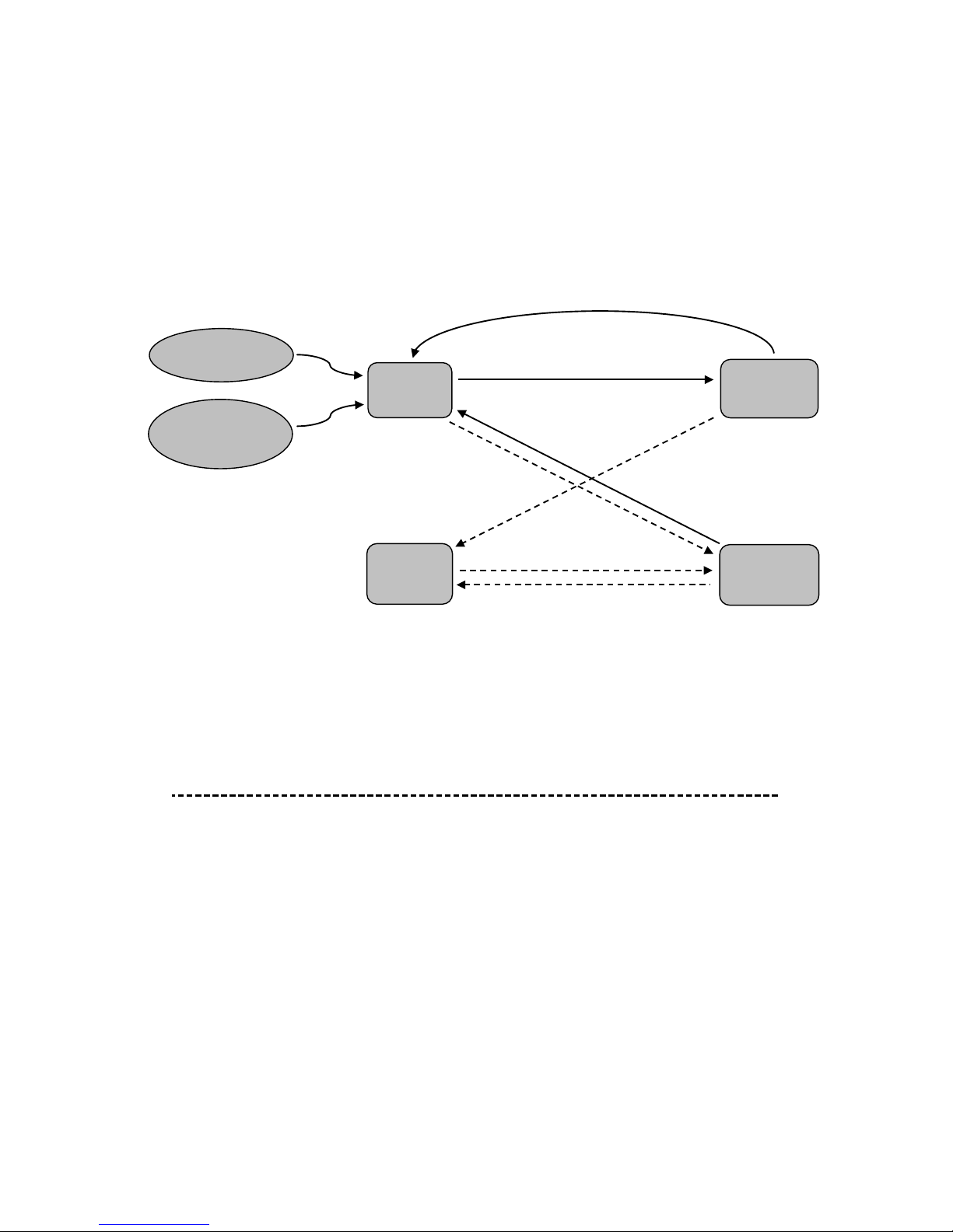
Attention:“——”means auto process; “-----” means manual process.
Figure 4-1 Charging Schematic Diagram
Section III Multi-machine Operation
Parallel Running
Multiple same type power supplies can be connected in parallel, but the
output voltage must be set at the same value. Turn on the power supplyone
by one. The load voltage is the same with each power supply and the load
current is the sum of each power supply. The wiring diagram is shown
below.
Auto
Float
Equalize duration time accomplished
Power On
Factory
Reset
Auto
Equalize
Manual
Float
Manual
Equalize
Equalize interval time accomplished
By pressing “MEC” button
By pressing “MFC” button
By pressing
“MFC” button
Equalize duration
time accomplished
By pressing
“MEC” button
-10-
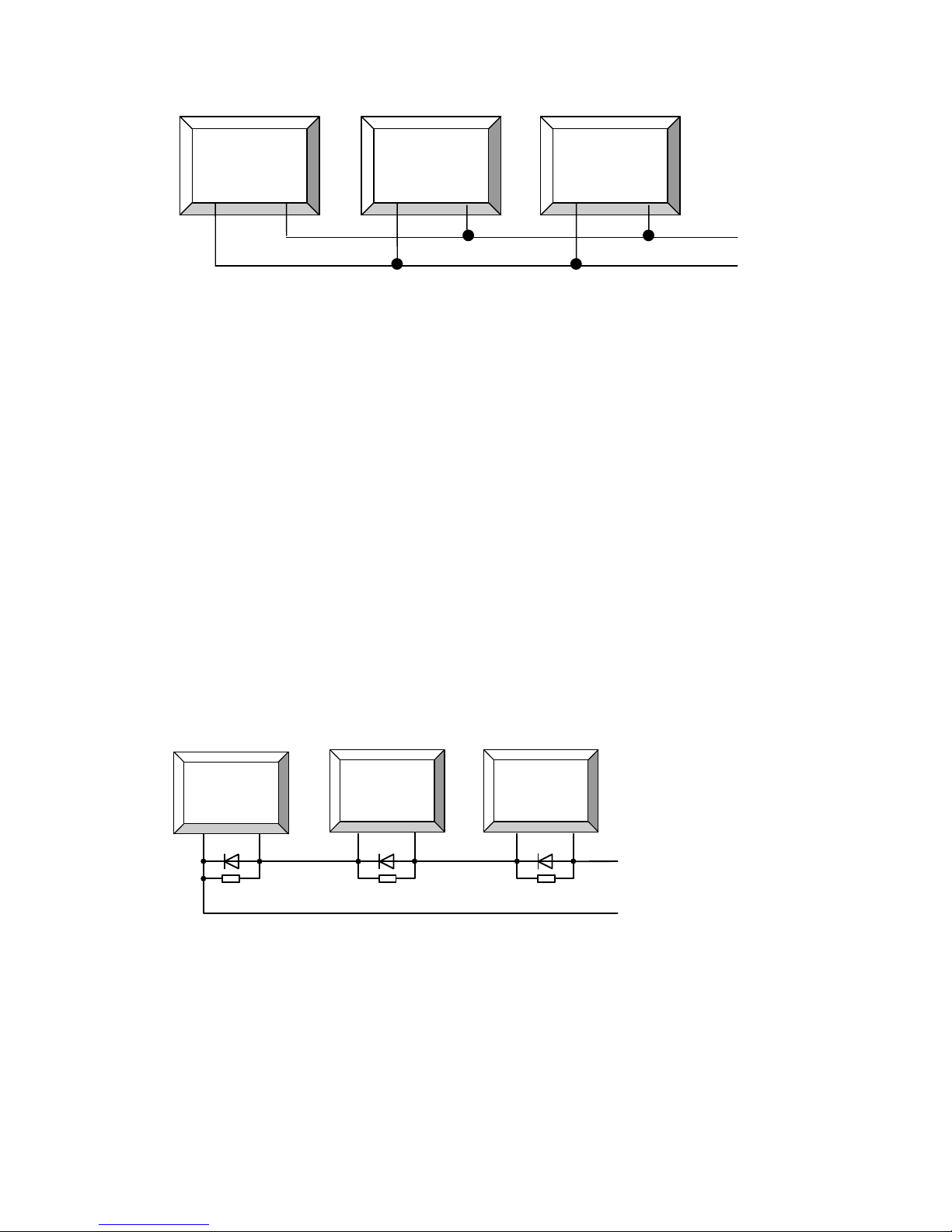
Figure 4-2 Parallel connection
Series Running
Multiple same type equipments can be connected in series, but the current
value of output should be set consistently. Turn on the power supply one
by one. The load current is the same with each power supply and the
voltage is the sum of each power supply. The wiring diagram is shown
below.
Suggest: The output of each power supply should parallel a power
resistance of 10k / 1w and a protection diode (pay attention to the
technical parameters of the diode).
Cathode -
Anode +
Digital power
supply
+ -
Digital power
supply
+ -
Digital power
supply
+ -
Figure 4-3 Series connection
Digital
power
supply
Digital
power
supply
Digital
power
supply
Cathode -
Anode +
-11-

Chapter V OPERATION INTERFACE
Section I Panel Shows
Front Panel:
Figure 5-1 Front panel
Rear Panel:
Figure 5-2 Rear panel
Illustrate:
①ON/OFF switch
②Human-machine interface
③RS485 port
④CAN bus port
⑤DC output Negative terminal
⑥DC output Positive terminal
⑦DC output fuse
⑧AC input socket with insurance
(Note: CAN bus port is reserved)
2
1
3
5
6
7
8
4
-12-

Section II Human-Machine Interface
Figure 5-3 Human-machine interface
Table5-1 Interface specification
Items
Code
Color
Action
Function
Remark
LED indications
CV
Green
On solid
Constant-voltage
output
CC
Red
On solid
Constant-current
output
EC
Green
On solid
Automatic
equalize
charging mode
Green
Blink
Forced equalize
charging mode
FC
Yellow
On solid
Automatic float
charging mode
Yellow
Blink
Forced float
charging mode
MODE
Green
Off
Power Mode
Green
On solid
Charging Mode
ALARM
Red
and
Green
Specific to see “Table
6-1 The state table of
protection”
Soft-touch
button
MEC
Forced equalize
charging mode
Valid only in charging
mode
MFC
Forced float
charging mode
Valid only in charging
mode
MENU
Menu switch
Switch between the
interface of real-time,
-13-

setting and failure.
SET
Enter setting
Exit setting without
saving if no operation
within 60 seconds.
ESC
Exit setting
OK
Confirm setting
↑ ↓
Change the
setting value or
the page of
interface
← →
Move the cursor
between the bits
of the value or the
page of interface
MODE
Switch between
the power mode
and charging
mode
Display the last
operation mode when
turning on the power
each time.
OUT
Turn on or off the
output
Turn the output on or off
on any page except
setting state
Alarm buzzer
The alarm of
faults ;
Button operation
tips;
Buzzing when
pressing any
button each time
“*” tube
Display the
parameters,
failure tips and so
on
Interface description: The interface includes three parts,
real-time, setting and failure. The page of failure does not exist
when there is no failure. Each interface contains several pages
to display the actual contents.
Press ↑or ↓button to flip page cyclically. Press ←or →button
to jump to the first or last page of the interface.
-14-

The power mode or charging mode, real-time clock and day
generating capacity will not be changed or cleared. They will
maintain the current mode or parameters when restoring the
factory settings.
When restoring the factory settings, the device will be
converted to the automatic float charging mode. The Equalize
Duration and the Equalize Calendar are cleared.
The last working mode and parameters will be selected when
turning on the power supply.
Section III Display Operation
Initialization
The device type is displayed firstly when turning on
the power.
Power Mode
The interface will be changed circularly between the interface of real-time,
setting and failure when pressing MENU. Press↑or ↓button to flip
the page cyclically. Press ←or→button to jump to the first or last page.
▼Real-time Interface — Output Voltage
The interface of “Real-time Output Voltage” will be
displayed if the initialization is normal. During
setting , the first digit flashes when pressing SET,
EG1200CU
V.OUT 48.0
ID. 02 1.IOVP
V.OUT 48.0
MENU
MENU
MENU
-15-

the flashing bit will be moved right or left by
pressing →or ←, the value will be added or
subtracted by pressing ↑or ↓. Press OK or ESC
button to save the value or not. The current status
will be maintained when setting up the device.
▼Real-time Interface — Output Current
The output current value can be set directly in this
page. The setting procedure is the same with the
“output voltage”. The device will not stop running
when setting in both modes.
▼Real-time — Output Power
Real-time output power can’t be set in both modes.
▼Real-time — Input Voltage
Real-time input voltage can’t be set in both
modes.
▼Real-time — Date
The real-time date value can be set in this page.
The setting procedure is the same with the
“output voltage” in both modes.
▼Real-time — Time
The real-time time value can be set in this page.
The setting procedure is the same with the
“output voltage”. This page exists in both modes.
▼Set Interface — Device Address
The device’s ID can be set in this page without
C.OUT 20.0
P.OUT 1200
V.IN 220
DT.14.05.18
TM.09.12.55
ID. 02
-16-
Table of contents
Other Epever Power Supply manuals

Popular Power Supply manuals by other brands

Videx
Videx 520MR Installation instruction

Poppstar
Poppstar 1008821 Instructions for use

TDK-Lambda
TDK-Lambda LZS-A1000-3 Installation, operation and maintenance manual

TDK-Lambda
TDK-Lambda 500A instruction manual

Calira
Calira EVS 17/07-DS/IU operating instructions

Monacor
Monacor PS-12CCD instruction manual


