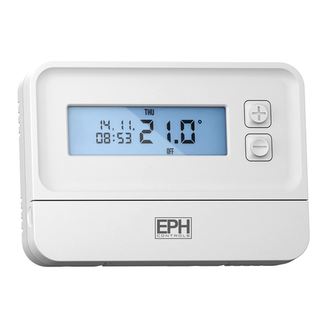
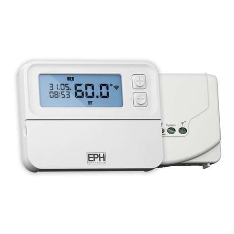
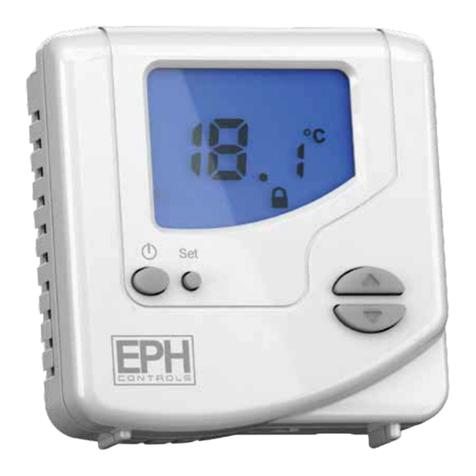
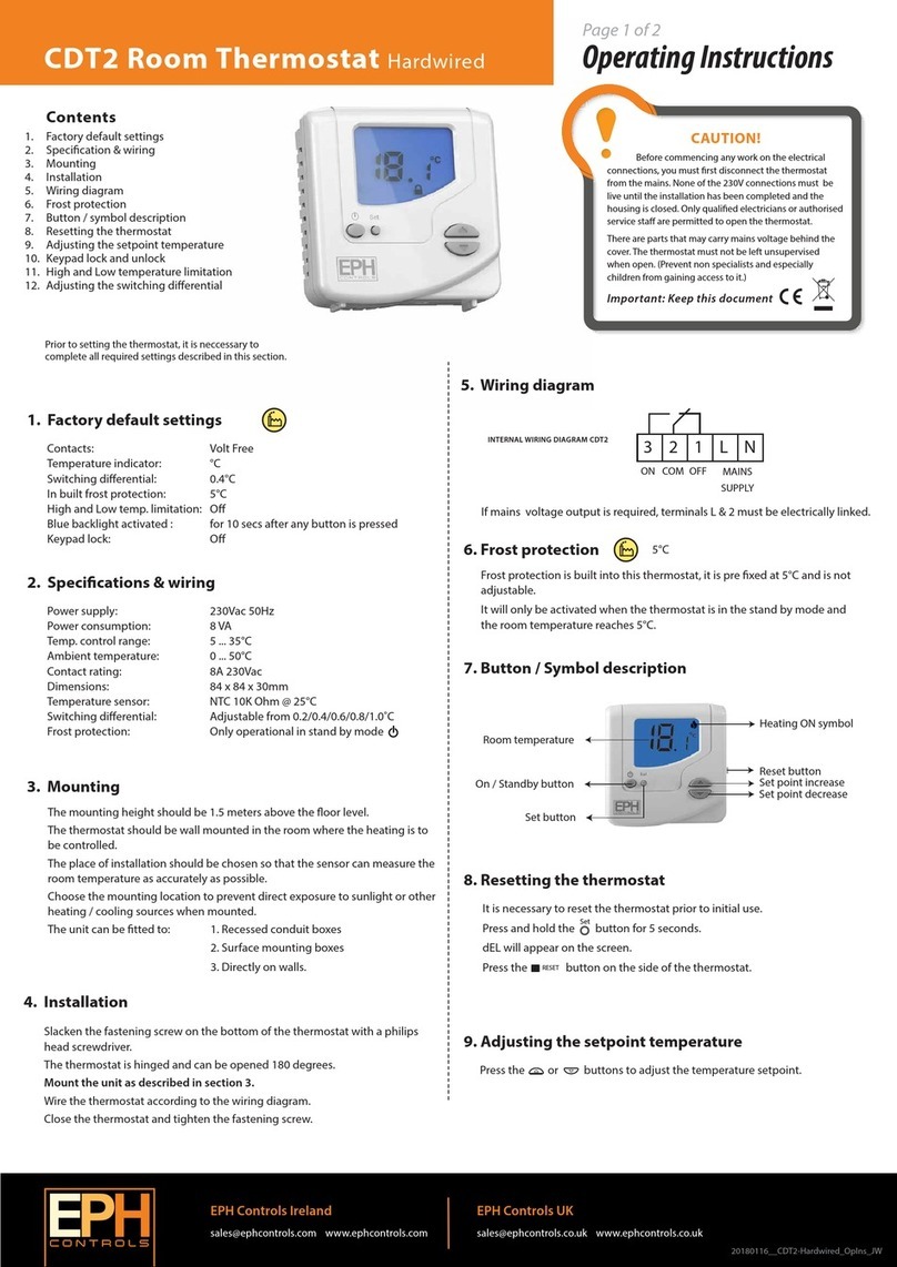
EPH COMBIPACK3 User manual

COMBIPACK3 Easy User Guide (Page 1 of 1)
Wireless Non Programmable Thermostat RFRA
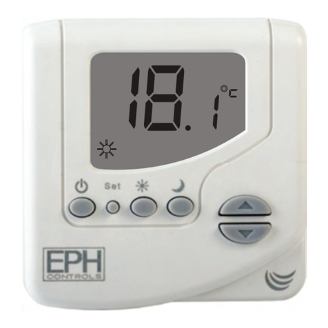
Button / Symbol Description
Setting the Temperature
On / O function
Room temperature On / Off button
Battery low symbol
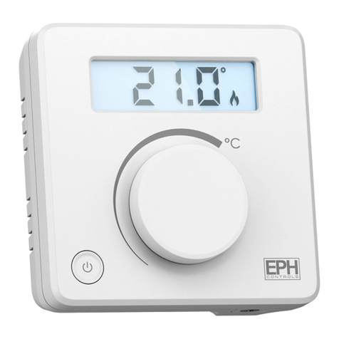
Set point handwheel
Heating ON symbol
Rotate the handwheel clockwise to turn up the temperature.
Rotate the handwheel anti-clockwise to turn down the temperature.
By pressing the On / Off button, this turns the thermostat on and off.
20180219_COMBIPACK3_EasyUserGuide_JW
EPH Controls Ireland
sales@ephcontrols.com www.ephcontrols.com
EPH Controls UK
sales@ephcontrols.co.uk www.ephcontrols.co.uk

CAUTION!
Before commencing any work on the electrical
connections, you must first disconnect the device from
the mains. None of the 230V connections must be live
until the installation has been completed and the housing
is closed. Only qualified electricians or authorised service
staff are permitted to open the terminal box.
There are parts that carry mains voltage behind the cover.
The terminal box must not be left unsupervised when
open. (Prevent non specialists and especially children
from gaining access to it.)
Ensure that this wireless enabled receiver is installed 1
metre from any metalic object, television, radio or wireless
internet transmitter.
EPH Controls Ireland
sales@ephcontrols.com www.ephcontrols.com
EPH Controls UK
sales@ephcontrols.co.uk www.ephcontrols.co.uk
20180826_RF1_OpIns_JW
Operating Instructions
Page 1 of 1
RF1 - Wireless Receiver
3. Installation
1. Specifications & wiring
5. Resetting the RF1 receiver
6. To connect the RF1 receiver to a RFRA
thermostat
7. To disconnect the RFRA thermostat from a
RF1 receiver
2. Mounting
Contents
1. Specifications & wiring
2. Mounting
3. Installation
4. Button / LED description
5. Resetting the RF1 receiver
6. To connect the RF1 receiver to a RFRA
wireless thermostat
7. To disconnect the RFRA thermostat from a
RF1 receiver
Prior to operation, it is neccessary to complete all required settings described in this section.
4. Button / LED description (Continued)
4. Button / symbol description
Important: Keep this document
The RF1 receiver should be wall mounted in an area within 20 metres
distance of the wireless thermostat.
It is important that the receiver is mounted more than 1 metre away from
metal objects as this will affect communication with the thermostat.
The receiver should also be installed at least 1metre from any electronic
devices such as radio, TV, microwave or wireless network adaptor.
The unit can be fitted to: 1. Recessed conduit boxes
2. Surface mounting boxes
On the RF1 receiver
Press the reset button on the right side of the housing.
Within 2 seconds, press the connect button.
The RF1 receiver is now disconnected from the RFRA thermostat.
On the RFRA thermostat
Press the button on the bottom of the thermostat, the front housing
will detach from the baseplate.
Press the RESET button on the printed circuit board.“NO” will flash on the
screen.
Rotate the hand wheel clockwise until “YES”appears on the screen.
Press the hand wheel once to confirm the setting.
The thermostat is now disconnected to the receiver.
* If mains voltage output is required,
terminals L & 2 must be electrically linked.
OFFON
321LN
L
MAINS
SUPPLY
N
COM
Power Supply: 230 Vac 50Hz
Contact Rating: 250 Vac 10(3)A
Ambient Temp: 0~50°C
Class II appliance
Pollution degree 2: Resistance to
voltage surge 2500V; as per EN 60730
Internal wiring diagram for RF1
Slacken the fastening screw on the bottom of the receiver with a philips
screwdriver.
The receiver is hinged and can be opened 180 degrees. Mount the unit as
described in section 2. Wire the unit as described in section 1. Close the
receiver and tighten the fastening screw.
System ON
(Green LED)
Manual override
Connect button
Wireless connect
indicator (Red LED)
Reset button
Wireless connect: Once voltage has been applied this button may be
pressed to initialise the pairing process with the wireless thermostat. Once
pressed the red LED will begin to flash.
Manual override: This button will manually override the system.
Wireless connect indicator: This LED will flash on receiving wireless signals.
If it is constantly ON, the RF1 receiver has been disconnected from the
wireless thermostat.
The wireless connect LED will be constant red once power has been applied.
Press the button on the RF1 receiver.
Both the red and green LED on the RF1 will begin to flash.
On the RFRA thermostat, press the button on the bottom of the
thermostat, the front housing will detach from the baseplate.
Press the CODE button on the printed circuit board.
When r1 appears on the screen, press the hand wheel once.
The thermostat is now connected to the RF1 receiver.
Connect
Press the button located on the side of the receiver. Within 2 seconds,
press press the connect button. The RF1 receiver is now reset.
RESET

For use in normal environments.
RFRA - RF Room Thermostat Installation Instructions
Page 1 of 1
1
34
5 6
2
If this device is used in a way not specified by the maufacturer, it’s safety may be impaired.
Ensure that this wireless enabled thermostat is installed 1 metre from any metallic object, television,
radio or wireless internet transmitter.
This thermostat can be mounted in the following ways:
To a recessed conduit box
To a surface mounted box
Directly mounted on wall
Table mounted with accessory provided.
CAUTION! Installation and connection should only be carried out by a qualified
person and in accordance with national wiring regulations.
Important: Keep this document
EPH Controls Ireland
sales@ephcontrols.com www.ephcontrols.com
EPH Controls UK
sales@ephcontrols.co.uk www.ephcontrols.co.uk
20180628_RFRA_InsIns_JW
21
2586
86
Press to open

CAUTION!
Only qualified electricians or authorised
service staff are permitted to open the
thermostat.
Ensure that this wireless enabled
thermostat is installed 1 metre from any
metalic object, television, radio or
wireless internet transmitter.
Operating Instructions
Page 1 of 2
RFRA - RF Room Thermostat
4. Installation
1. Factory default settings
6. Resetting the thermostat
7. On / Off function
8. Lock function
2. Specifications & wiring
Temperature indicator: °C
Switching differential: 0.2°C
In built frost protection: 5°C
Keypad lock: Off
3. Mounting
Contents
1. Factory default settings
2. Specification & wiring
3. Mounting
4. Installation
5. Button / symbol description
6. Resetting the thermostat
7. On / Off function
8. Lock function
9. To connect the RFRA thermostat to the
RF1 receiver
10. To disconnect the RFRA thermostat from
the RF1receiver
Prior to setting the thermostat, it is neccessary to complete all required settings described in this
section.
5. Button / symbol description
Important: Keep this document
Power Supply: 2 x AAA Alkaline Battery
Power consumption: 50 uA
Battery replacement: Once per year
Temp. Control Range: 5...35°C
Dimensions: 84 * 84 * 30mm
Temp. sensor: NTC 10K Ohm @ 25°C
Temp. indication: °C
The mounting height should be 1.5 meters above the floor level. The
thermostat should be wall mounted in the room where the heating is to
be controlled.
The place of installation should be chosen so that the sensor can measure
the room temperature as accurately as possible.
Choose the mounting location to prevent direct exposure to sunlight or
other heating / cooling sources when mounted.
The unit can be fitted to: 1. Recessed conduit boxes
2. Surface mounting boxes
3. Directly on walls
4. Table mounting with stand provided
Press the button on the bottom of the thermostat.
The front housing will detach from the baseplate.
Insert the batteries (provided) into the thermostat.
Mount the unit as described in section 3.
Offer the baseplate up to the thermostat. Snap it into position to close.
By pressing the On / Off button, this turns the thermostat on and off.
To lock the thermostat, press the hand wheel for 10 seconds.
symbol will appear on the screen.
To unlock the thermostat, press the hand wheel for 10 seconds.
symbol will disappear from the screen.
Press the button on the bottom of the thermostat, the front housing
will detach from the baseplate.
Insert the batteries into the thermostat.
Press the reset button on the PCB,‘NO’ will flash on the screen.
Rotate the hand wheel clockwise until ‘YES’appears on the screen.
Press the hand wheel once to confirm the setting.
The thermostat has now been reset and the current temperature will
appear on the screen.
Heating ON symbol
Room temperature Battery low symbol
Set point handwheel
Wireless symbol
Code buttonReset button
On / Off button
EPH Controls Ireland
sales@ephcontrols.com www.ephcontrols.com
EPH Controls UK
sales@ephcontrols.co.uk www.ephcontrols.co.uk
20180628_RFRA_OpIns_JW

Operating Instructions
Page 2 of 2
RFRA - RF Room Thermostat
10. To disconnect the RFRA thermostat from the RF1
receiver
9. To connect the RFRA thermostat to the RF1 receiver
On the RF1 receiver
Press the reset button on the right side of the housing.
Within 2 seconds, press the connect button.
The RF1 receiver is now disconnected from the RFRA thermostat.
On the RFRA thermostat
Press the button on the bottom of the thermostat, the front housing will
detach from the baseplate.
Press the RESET button on the printed circuit board.
“NO” will flash on the screen.
Rotate the hand wheel clockwise until “YES”appears on the screen.
Press the hand wheel once to confirm the setting.
The thermostat is now disconnected from the receiver.
On the front of the RF1 receiver
Press the connect button. The “System On” green LED will begin to flash.
On the RFRA thermostat
Press the button on the bottom of the thermostat, the front housing
will detach from the baseplate.
Press the CODE button on the printed circuit board.
When r1 appears on the screen, press the hand wheel once.
The thermostat is now connected to the receiver.
EPH Controls Ireland
sales@ephcontrols.com www.ephcontrols.com
EPH Controls UK
sales@ephcontrols.co.uk www.ephcontrols.co.uk
20180628_RFRA_OpIns_JW
Table of contents
Other EPH Thermostat manuals
Popular Thermostat manuals by other brands
Aube Technologies
Aube Technologies TH141-HC-28 user guide

Honeywell
Honeywell PCR-100 Installation and operating instructions
Honeywell Home
Honeywell Home TH8110R1008/U manual
Johnson Controls
Johnson Controls T-3102 Installation and Calibration Manual
Amana
Amana PHWT-A100C manual
Honeywell
Honeywell RTH6500 user guide
Tekmar
Tekmar tekmarNet 2 528 Installation & operation manual

Coati
Coati 12600 operating instructions
MICRO-AIR
MICRO-AIR EasyTouch RV Installation, Quick Start Guide and Operation Manual
Twite Instruments
Twite Instruments TD-196 operating manual

Helios
Helios TME 4 quick start guide
Viconics
Viconics VT7600A installation guide
