Spyder Robotics Herpstat EZ Series User manual

Herpstat EZ Series
User’s Manual
www.spyderrobotics.com
Thank you for choosing the Herpstat digital proportional thermostat. This product
offers the following features:
Proportional heating constantly monitors and adjusts amount of heat necessary to maintain a target
temperature (usable range from 70˚F to 110˚F).
Dimming and Pulse heating modes.
Basking Assist control built in to work with basking lights.
Glowing LED snake eyes indicate measured temperature and heat status.
Soft startup slowly applies power during initial warm-ups.
Auto Power Matching constantly adjusts the power output curve to match the enclosures efficiency.
Precision temperature sensors with an internal resolution of .1125 ˚F and are accurate to ± .9 ˚F
Removable sensors allow for easy replacement if necessary.
User replaceable fuse.
Audible alarm system.
30 minute low temperature alarm.
Over temperature alarm.
Internal error detection shuts off heat if sensor fails or is disconnected.
400 total watt output for the Herpstat EZ1
600 total watt output for the Herpstat EZ2
1 year limited warranty.
About this User's Manual
This manual covers both the Herpstat EZ1 and Herpstat EZ2 products. The Herpstat EZ2 adds a second output
and probe with its own independent setting knob.
Hardware Installation
WARNING – FIRE OR ELECTRICAL SHOCK MAY RESULT FROM MISUSE. FOR INDOOR USE ONLY!
Herpstat 1: Do not exceed 400 watts.
Herpstat 2: Do not exceed 300 watts on either output.
1. Each AC receptacle on the Herpstat has a corresponding probe jack on the side of the unit. On the
Herpstat EZ2 the probe jack on the top is used with the left dial and outlet. The lower probe jack
belongs to the dial and outlet on the right side of the unit. On the Herpstat EZ2 its very important to
keep the probe and outlets matched or else an overheat condition can occur.
2. Attach the Herpstat electrical cable to the bottom of the unit and to a standard wall outlet.
3. Attach the heating device to the AC outlet receptacles on the Herpstat. These devices may include
heat tape, heat coils, basking lights, ceramic heat emitters, heat mats or other resistive load heating
devices. Not recommended for use with rock heating devices or other devices that come in direct
contact with the animal. Do not connect oil-filled heaters or other space heaters.
Installation Tips:
We do not recommend using aluminum tape to secure the probes. This can cause false readings and
poor regulation.
Route the probe wires so that they are not in direct contact with the 120vac cables going to the heating devices.
Preferably leave at least a few inches between the probe wires and the AC lines to avoid cross talk/electrical
interference issues.
Mount the device in a dry indoor location away from additional heat and humidity sources. During operation it is
normal for the Herpstat's enclosure to be warm to the touch.
Electrical surges can damage a thermostat. Use a good quality surge suppressor connected between the wall
and Herpstat.
Setup Procedure
Install the probe where you want to measure / regulate temperature. Recommendations on probe placement
can be found on our website here:
http://www.spyderrobotics.com/probe
Adjust the knob to your desired temperature. The indicated temperatures on the thermostat are an
approximate setting in Fahrenheit. Use a separate thermometer in the enclosure and adjust the knob
accordingly to reach your desired temperature. When the knob is adjusted a short double beep will sound and
the LED will flash green indicating that it is recognizing a new temperature. Once it recognizes the dial has
stopped moving a three beep indicator will sound and the LED will flash green acknowledging the change.
NOTE: Any time a knob is adjusted the thermostat will wipe its previously learned power curves and
go through the process of relearning exactly how much power the enclosure needs to maintain the
new temperature. Give the unit time to adjust before determining if further changes are needed.
Checking Device Firmware:
When unit is first plugged in the LED’s will blink the firmware version. The number of red blinks on the left eye
is the whole number and the number of green blinks on the right eye will indicate the tenth of the revision.
Then an audible beep will sound indicating the unit is starting normal operation.

LED INDICATOR DESCRIPTION:
Each LED on the Herpstat EZ2 corresponds with the knob and outlet below it. On the Herpstat EZ1 unit both
LED’s are combined.
SOLID RED:
Measured temperature is more than 1 degree below the target temperature.
SOLID GREEN:
Measured temperature is within 1 degree above or below the target temperature.
NO ILLUMINATION:
Measured temperature is over 1 degree but less than 2 degrees above the target temperature. LED will also be
off if the knob is set to OFF.
BLINKING YELLOW:
Measured temperature is more than 2 degrees above the setting.
BLINKING RED TO GREEN:
Temperature probe error. Audible alarm sounds. Check probe connections and replace temperature probe if
error continues.
BLINKING RED:
Approximately 30 minutes has passed since power on or knob change and the measured temperature has not
made it to within 3 degrees of the target temp. Unit will continue to provide power to the heating device. User
should check temperatures to make sure there is not a setup problem.
ADVANCED SETTINGS: Heating Mode
Three heating modes are available. The heating mode applies to both outputs on the EZ2 model.
#1. Dimming mode #2. Pulse mode #3. Non-proportional mode
For most applications the default setting of Dimming mode is the best choice. The only time Pulse mode is
necessary is if the unit is controlling a metal rack system and slight audible hum emits from the rack. Non-
proportional mode is there for use when a poor power supply must be used such as a backup generator.
NOTE: Whenever using any other power source other than standard wall power the power needs to be of a
“pure” or “true” sinewave if using proportional control modes. If using a modified sinewave inverter or generic
generators the non-proportional mode is recommended and thorough testing should be done before relying on
operation.
TO ENTER PROGRAMMING MODE: Unplug the unit. Adjust the knob (left knob on the EZ2 model) to the
maximum clockwise rotation (greater than 110F). Plug the unit back in. A long five second beep will sound.
During that long beep adjust the knob to desired mode.
Dimming proportional mode: Adjust knob to 90 degrees
Pulse proportional mode: Adjust knob to 105 degrees
Non-proportional mode: Adjust knob to 75 degrees
At the end of the beep the LEFT LED will then light indicating which mode it is now in.
RED indicates the outputs are in Dimming mode.
GREEN indicates the outputs are in Pulse mode.
RAPID FLASHING red to green indicates the outputs are in Non-proportional mode.
An audible beep sequence will also indicate what mode then unit is in.
1 Short Beep = Dimming proportional mode (Safety OFF) 1 Long Beep = Dimming proportional mode (Safety ON)
2 Short Beeps = Pulse proportional mode (Safety OFF) 2 Long Beeps = Pulse proportional mode (Safety ON)
3 Short Beeps = Non-proportional mode (Safety OFF) 3 Long Beeps = Non-proportional mode (Safety ON)
This sequence is also heard every time the unit is first powered up.
ADVANCED SETTINGS: Safety Mode
These units include an optional safety mode. Because of how this feature affects the operation this mode must
be enabled by the user. Enabling the Safety Mode enables the following:
30 minute timeout additional alarm: If the temperature read by the probe is not within 3 degrees of the
temperature setting within 30 minutes of power up or a knob change then both outlets will turn off and an
audible alarm will sound.
Over temperature audible alarm: When measured temperature is 2 degrees or more over the temperature
setting the BLINKING YELLOW led indicator will also be accompanied by an audible alarm.
Over temperature shutdown (EZ2): If any measured temperature is 5 degrees or more above the temperature
setting both outlets will turn off.
Additional Probe Error Alarm (EZ2): Probe errors already turn off the associated outlet. When the safety mode
is enabled any error from either probe will turn off both outlets.
TO ADJUST THE SAFETY MODE: Unplug the unit. Adjust the knob (left knob on the EZ2 model) to the
maximum clockwise rotation (greater than 110F). Plug the unit back in. A long five second beep will sound.
During that long beep adjust the knob to the OFF position. This will switch the option between ON and OFF.
At the end of the beep the RIGHT LED will then light indicating which mode it is now in.
RED = (Default) Safety Mode is OFF GREEN = Safety Mode is ON
Getting the most out of your Herpstat (Troubleshooting)
In all thermostat applications the probe placement is the most important factor in good temperature
regulation. Our recommendations can be found on our website here:
http://www.spyderrobotics.com/support
When setting up a new environment allow a minimum of one hour for the temperature to stabilize. Keep in
mind that all items in the enclosure are warming up including the enclosure walls.
If after an hour of initial regulation the temperature does not reach within a degree of the target temperature
this is an indication of insufficient heating source. Add an additional heat device to the enclosure or switch to a
higher wattage heat device. Do not exceed the maximum watts per output.
The Herpstat has a user replaceable fuse. If the Herpstat appears to not operate while being plugged in the
fuse may have been damaged by a voltage spike or overload. Disconnect all cables to the unit including the
power. The power input connector on the bottom of the device has a built-in fuse drawer. Use a flathead
screwdriver and gently insert the tip into the recess and then lightly twist / pry the handle to pop open the fuse
drawer. A spare fuse is included and is inserted into the second spot of the holder. Replace the damaged fuse
with the new fuse and close the drawer fully to finish the process. IMPORTANT: Replace with correct fuse!
The Herpstat EZ1 uses a 4.0 amp 5x20mm fast acting fuse. The Herpstat EZ2 uses a 6.3 amp 5x20mm fast
acting fuse. Never bypass the safety fuse or use a larger fuse as it can become a serious safety hazard.
Additional fuses can be purchased through Spyder Robotics online webstore. We recommend keeping spares on
hand to avoid potential downtime should this scenario occur.
Do not cover the probe tip with aluminum tape. This will cause false readings and poor regulation.
If possible route the probe wires so that they are not in direct contact with the 120vac cables going to the
heating devices. Preferably leave at least a few inches between the probe wires and the AC lines to avoid cross
talk/electrical interference issues.
Getting Help
Questions or comments can be e-mailed to:
support@herpstat.com
To purchase accessories please visit us on the web at:
http://www.spyderrobotics.com
1 Year Limited Warranty
Spyder Robotics LLC warrants this product to be free from defects in workmanship and material for a period of one year from the date
of purchase by the original purchaser. The warranty period shall not extend beyond 3 years from the date Spyder Robotics LLC
shipped the product. During this warranty period Spyder Robotics LLC will repair or replace, at its option, any component parts that in
its opinion prove to be defective. Replacement parts may be new or serviceable used parts at Spyder Robotics LLC option, of equal or
better quality to those being replaced. This warranty does not extend and shall not apply to products that have been subjected to
misuse, neglect, accident, or improper installation.
THIS LIMITED WARRANTY AND REMEDY ARE EXCLUSIVE AND EXPRESSLY IN LIEU OF ALL OTHER WARRANTIES EXPRESSED OR
IMPLIED, INCLUDING BUT NOT LIMITED TO ANY IMPLIED WARRANTIES OF MECHANTABILITY AND FITNESS FOR A PARTICULAR
PURPOSE. IN NO EVENT SHALL SPYDER ROBOTICS LLC BE LIABLE FOR LOST PROFITS, LOSS OF GOODWILL, OR ANY OTHER
INCIDENTAL OR CONSEQUENTIAL DAMAGES.
If you return your product to Spyder Robotics LLC for warranty service, proof of purchase may be required. A Return Material
Authorization (RMA) number must be obtained prior to the return. Spyder Robotics LLC is not responsible for material returned
without the RMA number clearly printed on the outside of the shipping container. To request an RMA number, contact Spyder Robotics
LLC with the description of failure, serial number of device, and date of purchase via e-mail at returns@spyderrobotics.com.
©2017 Spyder Robotics LLC manual-HS012
http://www.spyderrobotics.com 11.15.2017
This manual suits for next models
2
Other Spyder Robotics Thermostat manuals
Spyder Robotics
Spyder Robotics Herpstat ND User manual
Spyder Robotics
Spyder Robotics Herpstat 1 User manual
Spyder Robotics
Spyder Robotics Herpstat HP User manual
Spyder Robotics
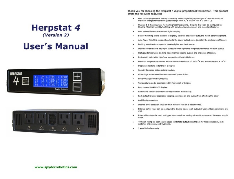
Spyder Robotics Herpstat 4 User manual

Spyder Robotics
Spyder Robotics Herpstat 1 User manual
Spyder Robotics
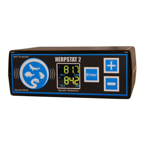
Spyder Robotics SpyderWeb Herpstat 2 User manual
Spyder Robotics
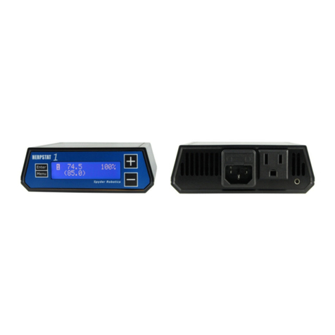
Spyder Robotics Herpstat 1 Basic User manual

