EPI ENVIRO Cover Deployer 800 Operation manual

Enviro™Cover Deployer Model 800
Dispensing System
Operation and Service Manual
EPI Environmental Products Inc.
Tel: +1 (604) 738-6281
, EPI and Enviro™are registered marks of EPI Environmental Products Inc.
Enviro™Cover System is protected by composition, method and apparatus
patents and patent applications worldwide.

All rights reserved. No part of this Manual may be reproduced or transmitted in any form or by any means, electronic or mechanical, including
photocopying, recording or by any information storage or retrieval system, without permission in writing from the publisher.
Doc #: EC501 / Rev. 1 / Effective Date: October 17, 2014
This Dispensing System Operation and Service Manual is an integral part of Enviro™ Cover
System. It provides important information and instructions on the equipment, loading,
dispensing, health and safety, operation, maintenance, lock-out procedure and information
on product warranty. This Manual is one of five Enviro™ Cover Deployer Model 800 manuals
(Morooka Track Carrier –Operation & Part and Engine –Operation & Part Manuals), which
should be kept easily accessible by Enviro™ Cover Deployer operator for reference.
The information presented in this literature is based on the best data available and is believed to be correct.
However, nothing stated herein is to be taken as warranty (unless specified), expressed or implied regarding the
accuracy of the information or the use of our product. Nor shall anything contained herein be construed to
constitute a permission or recommendation to practice any invention covered by a patent, patent application or
know-how owned by EPI Environmental Products Inc. or any subsidiaries of the Company.
Published and printed by:
EPI Environmental Products Inc.
#801 - 1788 West Broadway
Vancouver, B.C. Canada V6J 1Y1
Tel: +1 (604) 738-6281
Fax: +1 (604) 738-7839
Email: [email protected]
Website: www.envirocoversystem.com and www.epi-global.com
,, EPI and Enviro™are registered marks of EPI Environmental Products Inc. Enviro™Cover System is protected
by composition, method, and apparatus patents worldwide.
It is expressly understood and agreed that SELLER MAKES NO EXPRESS OR IMPLIED WARRANTIES OF FITNESS OR
OF MERCHANTABILITY OR OF ANY OTHER KIND WHATSOEVER except that the goods sold hereunder shall be of the
quality warranted in the Company’s Product Specifications. Buyer assumes all risk of liability whatsoever resulting
from the use of such goods, whether used singularly or in combination with others. Seller’s liability for non-
conforming goods is exclusively limited, at the seller’s option, to replacement of the defective goods or the
purchase price of such goods and under no circumstances shall Seller be liable for incidental or consequential
damages.

All rights reserved. No part of this Manual may be reproduced or transmitted in any form or by any means, electronic or mechanical, including
photocopying, recording or by any information storage or retrieval system, without permission in writing from the publisher.
Doc #: EC501 / Rev. 1 / Effective Date: October 17, 2014
Things You Should Know about Using Model 800 Manuals:
This Dispensing System Operation and Service Manual contains important information and
instructions on the equipment, accessories, features, health and safety, loading, operating
procedure, lock-out procedure, maintenance checklists and know-how of EPI’s Enviro™ Cover
System.
Please read through this Manual and all Model 800 related manuals carefully
and have the personnel trained before commencing the operation of Enviro™
Cover System.
This Manual describes the specifications of the equipment that were in effect when this Manual
was prepared. EPI reserves the right to change the specifications or to discontinue the models
without any notice and without incurring any liability.
If you have any questions about Enviro™Cover System, please contact EPI or your local EPI
representative.
EPI Environmental Products Inc.
Tel: +1 (604) 738-6281
Toll Free: +1 (866) 738-6281
Fax: +1 (604) 856-8189
Email: [email protected]
Canadian Corporate Office
#801 - 1788 West Broadway
Vancouver, BC V6J 1Y1 Canada
US Corporate Office
#207 - 102 Grover Street
Lynden, WA 98264, USA

All rights reserved. No part of this Manual may be reproduced or transmitted in any form or by any means, electronic or mechanical, including
photocopying, recording or by any information storage or retrieval system, without permission in writing from the publisher.
Doc #: EC501 / Rev. 1 / Effective Date: October 17, 2014
Table of Contents
Page
1
Enviro™ Cover System
1-2
2
Health and Safety Introduction
3-4
3
General Specifications
5
4
Off Loading Procedures
6
5
Decal Layout
7
6
Components Guide
8-13
7
Installation of EC Roll
14
8
Ground Attendant Operational Hand Signals
15-16
9
EC Deployment and Safety Decal
17-24
10
Daily Checklist
25
11
Pre-Delivery Checklist
26
12
Maintenance Checklist & Lock-Out Procedure
27
13
Electrical and Hydraulic Schematic Diagrams
28-29
14
Training Sign-off Record
30
15
Notes
31
All rights reserved. No part of this Manual may be reproduced or transmitted in any form or by any means, electronic or mechanical, including
photocopying, recording or by any information storage or retrieval system, without permission in writing from the publisher.
Doc #: EC501 / Rev. 1 / Effective Date: October 17, 2014
1
Chapter 1 Enviro™Cover System
Enviro™Cover
Enviro™ Cover (EC) is a non-reusable engineered geosynthetic alternative daily cover as
classified by ASTM D6523. It is a plastic film meeting established and regulatory criteria for
landfill daily cover.
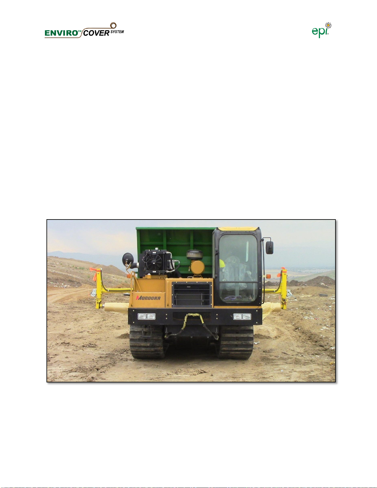
Enviro™ Cover Deployer
Enviro™ Cover Deployer Model 800 (ECD) is the equipment that applies EC and dispenses
ballast material onto the EC panel. It is a customized self propelled unit.
The equipment and the application method developed by EPI for laying film on the working face
of a landfill.
Figure 1: Enviro™ Cover Deployer Model 800
Table of contents


