EPIC SAFETY Surf-k User manual

surf-k & surf-km
LTE Alarm System Communicators
Installation Guide
V1.0
2
1.Overview
1.1.Description
Surf-K and Surf-KM are primary alarm communicators that use cellular (LTE) technology. They
use dial capture to monitor any alarm system that uses Contact ID (CID) and SIA formats. They
can also connect to the keybus on supported DSC and Honeywell panels to monitor these
systems and provide users the ability to access their systems remotely from anywhere via Aryo
Cloud platform on the web and on iOS and Android smartphones.
Surf-K/KM uses 3 zones to monitor legacy systems for legacy burglary, fire, and panic alarms.
Surf-K/KM uses zone 1 and PGM 1 for keyswitch arming and disarming. Refer to Section 5
(PGM Output Functions) for information on the PGM automation functionality.
1.2.In the Box
•surf-k or surf-km
•Antenna (75cm)
•Quick Start Guide
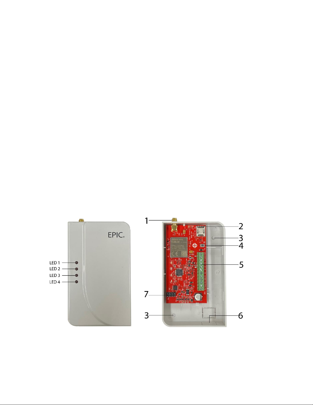
1.3.Parts Identification

3
1) Antenna connector
2) SIM card
3) Mounting holes
4) Button
5) Terminal block
6) Wire entrance
7) RF expansion port
2.Introduction
2.1.Device & Cloud Features
Surf-K and Surf-KM:
•Cover a wide area using low-power cellular technology using LTE, NB-IoT by Surf-K and LTE,
CAT-M1 by Surf-KM.
•Take over any alarm system whether locked or not.
•Monitor any system with little to no programming.
•Provide keybus, dial capture, and legacy monitoring options for alarm panels.
•Connect to Aryo cloud for remote control and monitoring.
•Support DSC PowerSeries & Honeywell keybus, SIA & CID formats for all other panels.
•Allow for concurrent use of landline digital account and LTE account.
•Enable full supervision and automatic device & panel status detection.
•Provide full event reporting to Aryo cloud and Central Monitoring Station (CMS).
•Send panel and device troubles for remote diagnostics.
•Support flexible use of 2 PGMs for automation.
•Enable up to 2-partition keyswitch arming when using dial capture.
•Use one master code (for the main user) and up to 40 user codes to arm and disarm the
alarm panel when keybus is not used. The master code can be reprogrammed by the
installer only.
Aryo cloud platform:
•Provides comprehensive reports and analytics.
•Displays zones, partitions, events, and status on up to 8 partitions or account numbers.
•Enables effortless cancellation of false alarms and dispatch of resources.
•Provides access to full-function mobile keypad when keybus is used.
•Supports permission-based roles and functions for utmost security.
•Enables end-to-end device & user data encryption for enhanced protection.
•Sends Push, Email & SMS Notifications.

4
•Allows for managing multiple alarm systems within the same app.
2.2.Monitoring Options
•Keybus enables Surf-K/KM to communicate with the panel and keypads directly for faster
status reporting. It also allows for use of additional commands such as zone status,
bypass/unbypass, and no entry delay arm. Keybus monitoring is available for DSC
PowerSeries and Honeywell Vista series panels. Connect YEL and GRN terminals to keybus
terminals of these panels to fully interact with the alarm panel. The events and status signals
are sent to Aryo cloud and the CMS.
•In case the alarm panel does not support keybus, Surf-K/KM is able to arm and disarm the
system through keyswitch arming.
•Dial capture allows Surf-K/KM to detect and capture CID and SIA events and monitor any
alarm system that uses these two formats. Dial capture monitoring is available to connect
the TIP and RNG terminals to any panel that can communicate in CID and SIA formats. The
signals are captured and sent to Aryo cloud and the CMS.
•Keybus and dial capture can be used together for fully control and monitoring the alarm
panel, through connecting the corresponding terminals.
•Legacy monitoring is also available, in case the panel does not support CID/SIA formats.
Surf-K/KM can use 3 input zones to monitor legacy alarm panel outputs by providing
burglary, fire, and panic alarms. These signals are then sent to Aryo cloud and the CMS.
3.Pre-Installation Recommendations
•Conduct a placement test to find a suitable location with the best LTE signal.
•Wiring can only be done when both Surf-K/KM and the alarm panel are powered down.
•DO NOT route any wire over the alarm panel or Surf-K/KM circuit boards.
•Install and program your alarm panel before connecting it to Surf-K/KM.
•Use only one device per alarm panel.
•Install and operate Surf-K/KM within its specified temperature range to prevent any possible
damage.
•DO NOT install the unit close to a heating source, direct sunlight, or in a damp location.
•DO NOT connect Surf-K/KM to a phone line. This will damage the device.
•Always connect Surf-K/KM to an approved power source and battery backup.
3.1.Antenna
•Surf-K/KM uses a full-band LTE magnetic antenna. The antenna can be connected to Surf-
K/KM antenna connector as shown in section 1.3.
•Antenna should be placed high in an open area within the building and far from any
interference by heating ducts, metal pipes, or electrical wiring and concrete walls.
•DO NOT install the antenna in a metal enclosure.

5
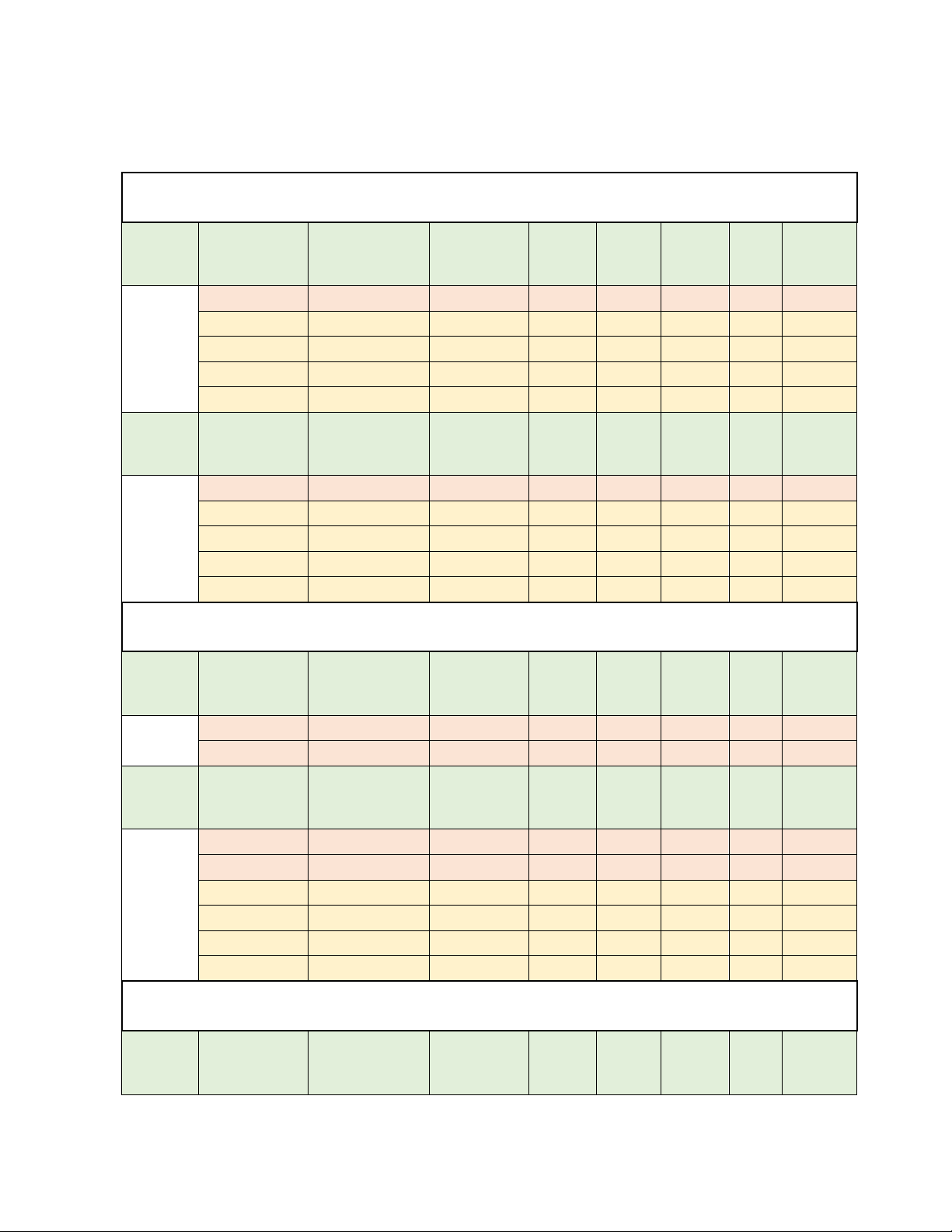
3.2.Cable Length
Using Station Z or CAT 5 type wires. Surf-K/KM can be installed up to 1000 feet away from the
alarm panel. For installations with over 1000 feet distance between the alarm panel and the
device, use higher gauge wire(s) as per the guidelines below.
Cable Type & Size
Number
of wires
Communication
Format
Keybus &
Power
Keybus &
Tip/Ring
Tip/Ring
& Power
Keybus &
Tip/Ring &
Power
Station Z
4 x 22AWG
DO NOT CONNECT SPARE
WIRES
One
wire
Keybus
1000ft
-
-
-
CID
-
200ft
1000ft
-
SIA
-
100ft
1000ft
-
Two
wires
Keybus
1000ft
-
-
-
CID
-
1000ft
1000ft
-
SIA
-
1000ft
1000ft
-
Three
wires
Keybus
-
-
-
-
CID
-
-
-
1000ft
SIA
-
-
-
1000ft
CAT 5
8 x 24AWG
DO NOT CONNECT SPARE
WIRES
Power +: Orange pair
Power -: Blue pair
Keybus GRN: Green
Keybus YEL: White/Green
TIP: Brown
RING: White/Brown
One
wire
Keybus
1000ft
-
-
-
CID
-
1000ft
1000ft
200ft
SIA
-
1000ft*
1000ft
200ft
Two
wires
Keybus
1000ft
-
-
-
CID
-
1000ft
1000ft
1000ft
SIA
-
1000ft
1000ft
1000ft
Three
wires
Keybus
-
-
-
-
CID
-
-
-
1000ft
SIA
-
-
-
1000ft
*For this specific configuration, power cable must not exceed 500ft.
4.Performance Guide
4.1.Signal Level
The signal level is reported using RSSI (Received Signal Strength Indicator) method which can
be converted to dBm (decibel-milliwatts). The RSSI and corresponding signal strength bar can
be seen in the table below:
RSSI
Signal Level (dBm)
Service Level
99
NA
No service
0 - 2
-113 ~-109

6
3 - 9
-108 ~-95
Poor –Device will trigger signal strength
trouble event.
10 -14
-93 ~-85
Acceptable
15 - 19
-83 ~-75
Good
20 - 31
-73 ~-51
Excellent
4.2.Temperature
For correct operation, the device must be in the operating temperature range. The different
temperature levels and their corresponding interpretations are listed below. The device’s
temperature is displayed and reported on Aryo cloud.
SURF-K/KM (°C)
Interpretation
< -5 °C
Low –Device will trigger low temperature trouble event.
-5 °C to 50 °C
Normal
> 51 °C
High –Device will trigger high temperature trouble event.
4.3.Voltage
For proper operation, both alarm panel and Surf-K/KM should be powered by an approved
power source within the recommended range. Different voltage levels and corresponding
interpretations for the alarm panel are listed below.
Panel Voltage (VDC)
Interpretation
< 9
Low voltage - Device will trigger low voltage trouble
event.
10.1 –13
Acceptable
13.1 –14.5
Good
> 14.5
High voltage - Device will trigger high voltage trouble
event.
4.4.Button Functions
Surf-K/KM button functions described in the table below:
Button Press
Time (sec)
Function
Name
Function Use
Duration time
LED Indicators
1 sec
Self-Test
To send device information
such as signal level, voltage,
Immediate
Blinks once

7
4.5.LED Indications
Condition
Status
LED
Color
On
Off
Fast
blink
1 blink
2 blinks
On-1
blink
Power
DC power on
1
Red
X
DC power off
1
Red
X
Device not registered
1
Red
X
Device troubles
1
Red
X
and temperature to Aryo
cloud.
5 sec
Signal Level
Mode
To select the best mounting
location based on the signal
level of Surf-K/KM.
LED Indications RSSI
LED 1 Blink 0 ~ 9
LED 1 On 10 ~ 12
LED 2 Blink 13 ~ 16
LED 2 On 17 ~ 19
LED 3 Blink 20 ~ 22
LED 3 On 23 ~ 25
LED 4 Blink 26 ~ 28
LED 4 On 29 ~ 31
30 sec
Slow blinking
10 sec
Reboot
Device
If required following the
troubleshooting guide in
Section 7.2.
Immediately
Fast blinking
15 sec
Reset SSL
When a device is reused for a
new client or moved to a new
location.
Immediately
Alternate blinking

8
Cellular
Network
Cannot find the cellular
network
2
Green
X
Poor signal
2
Green
X
Acceptable signal
2
Green
X
Good signal
2
Green
X
Excellent signal
2
Green
X
Server Network
Connecting to server
3
Green
X
Disconnected from server
3
Green
X
Communicating with
server
3
Green
X
Connection with server is
normal, but not
communicating
3
Green
X
Panel
Communication
Dial Capture
4
Green
X
Keybus
4
Green
X
Dial Capture and Keybus
4
Green
X
Legacy
4
Green
X
Firmware update in
progress
All
Red/Gree
n
Alternating LEDs.
LEDs 1&2 are on/off while LEDs 3&4 are off/on.
4.6.Terminal Connections

9
4.6.1.Surf-K/KM Terminals Description
Surf-K/KM terminals and their connections to alarm panel are described in the table below:
Surf-K/KM
Terminal
Alarm panel Terminal
Description
Tip (TIP)
TIP
Surf-K/KM TIP/RNG terminals connect to
the Tip/Ring interface of any alarm panel
that uses CID or SIA format to capture all
generated signals and send them to Aryo
cloud and the CMS.
Ring (RNG)
RING
Keybus Yellow
(YEL)
YEL
Surf-K/KM supports DSC PowerSeries and
Honeywell keybus interface. Yellow (YEL)
and Green (GRN) terminals can be
connected to Surf-K/KM YEL and GRN to
allow interaction with DSC PowerSeries
panels to monitor events and provide
status of the alarm panel.
Keybus Green
(GRN)
GRN
PGM 1 (P1)
Keyswitch zone(s) or used for
automation
Surf-K/KM has two PGM outputs for
keyswitch arming, for remote
arming/disarming, and automation
functionality for variety of purposes, as
outlined in Section 5.
PGM 2 (P2)
Zone 1 (Z1)
(Dry contact
only)
Available PGM
Always use a relay when connecting
panel PGM that supplies
voltage/current to the Surf-K/KM
zone. Otherwise, it will damage the
device.
Surf-K/KM zone 1 can be connected to
alarm panel PGM to receive arm/disarm
status of partition 1.
Zone 2 (Z2)
(Dry contact
only)
Siren output
Always use a relay on Siren/bell out
put for monitoring burglary and/or
fire.
Surf-K/KM Zone 2 is used as the common
burglary input to monitor the burglary
alarm signal received from the alarm
panel output. For DSC panels, this zone
can be used for both fire and burglary
detection when connected to the siren
output.
Zone 3 (Z3)
(Dry contact
only)
Available PGM
Always use a relay when connecting
panel PGM that supplies
voltage/current to the Surf-K/KM
zone. Otherwise, it will damage the
device.
Surf-K/KM Zone 3 is used as the common
fire input to monitor the fire alarm signal
received from the alarm panel output.

10
Zone 4 (Z4)
(Dry contact
only)
Available PGM
Always use a relay when connecting
panel PGM that supplies
voltage/current to the Surf-K/KM
zone. Otherwise, it will damage the
device.
Surf-K/KM Zone 4 is used as the common
panic input to monitor the panic alarm
signal received from the alarm panel
output. Alternatively, the panic alarm can
be programmed as audible to send
burglary signal.
It can also provide arm/disarm status of
partition 2 of the panel when not
monitoring legacy panels.
Ground (GND)
Ground
Surf-K/KM could be powered by an alarm
panel auxiliary 9-14 VDC. External
auxiliary power source with backup
battery can be used if they use a common
ground. These devices can still operate
with a power range of 6 to 20 VDC. Surf-
K/KM monitors panel voltage and
generates power trouble when voltage
drops below 9 VDC.
Power (PWR)
9-14 VDC
4.6.2.Other Hardware Connections
•RF expansion port is for future addition of more wireless capabilities to Surf-K/KM.
•Antenna connector is for connecting the LTE antenna.
5.PGM Output Functions (Automation)
5.1.Features
Surf-K/KM provides 2 programmable outputs (PGMs) to be used for various use cases. These
PGMs can be used to control gates, garage doors, sirens, and strobe lights, among various
other uses depending on Surf-K/KM communication type. See the table in section 5.4 for the
details.
5.2.Keyswitch - Dial Capture/ Legacy
When using Surf-K/KM for dial capture or legacy monitoring and remote arm/disarm, PGM 1
must be connected to a keyswitch zone on the alarm panel. For remote arm/disarm on 2
partitions systems (dial capture only), PGM 2 must be connected to another keyswitch zone
on the alarm panel. Any available PGM can be used for automation functionality.
5.3.Keybus
When using keybus for monitoring, both PGM 1 and 2 can be used for automation
functionality, as remote arm/disarm is handled by the keybus connections.
11
5.4.PGM Output Function Table
1. Using Keybus
Output
Momentary/
Maintained
Time Duration
Keyswitch
1
Garage
Door
Open
Door
Strike
Open
Gates
Siren
Strobe
PGM 1
Momentary
2 sec
O
Maintained
5 sec -300 sec
O
Maintained
5 sec -300 sec
O
Maintained
5 sec -300 sec
O
Maintained
5 sec -300 sec
O
Output
Momentary/
Maintained
Time Duration
Keyswitch
2
Garage
Door
Open
Door
Strike
Open
Gates
Siren
Strobe
PGM 2
Momentary
2 sec
O
Maintained
5 sec -300 sec
O
Maintained
5 sec -300 sec
O
Maintained
5 sec -300 sec
O
Maintained
5 sec -300 sec
O
2. Using Dial Capture (Tip/Ring)
Output
Momentary/
Maintained
Time Duration
Keyswitch
1
Garage
Door
Open
Door
Strike
Open
Gates
Siren
Strobe
PGM 1
Momentary
1 sec
O
Momentary
2 sec
O
Output
Momentary/
Maintained
Time Duration
Keyswitch
2
Garage
Door
Open
Door
Strike
Open
Gates
Siren
Strobe
PGM 2
Momentary
1 sec
O
Momentary
2 sec
O
Maintained
5 sec -300 sec
O
Maintained
5 sec -300 sec
O
Maintained
5 sec -300 sec
O
Maintained
5 sec -300 sec
O
3. Using Legacy
Output
Momentary/
Maintained
Time Duration
Keyswitch
1
Garage
Door
Open
Door
Strike
Open
Gates
Siren
Strobe

12
PGM 1
Momentary
1 sec
O
Momentary
2 sec
O
Output
Momentary/
Maintained
Time Duration
Keyswitch
2
Garage
Door
Open
Door
Strike
Open
Gates
Siren
Strobe
PGM 2
Momentary
2 sec
O
Maintained
5 sec -300 sec
O
Maintained
5 sec -300 sec
O
Maintained
5 sec -300 sec
O
Maintained
5 sec -300 sec
O
6.Installation & Programming
6.1.DSC PowerSeries Alarm Panels
6.1.1.Keybus Monitoring
DSC PowerSeries alarm panels can be connected to Surf-K/KM via keybus terminals to
monitor and control the alarm system remotely. All keybus functionalities are also available
for users on the app.

13
6.1.1.1.Wiring Diagram
6.1.1.2.Programming Instructions
Make sure to disable communications and program the alarm panel as a local system. No
further programming is required for keybus monitoring of DSC PowerSeries panels.
Keybus-compatible DSC Power Series alarm panels:
PC1864, PC1832, PC1616, PC5020, PC5010, PC1575, PC1565, PC1555, PC585, PC580
6.1.2.Keybus and Digital Account Monitoring
When DSC PowerSeries alarm panels are connected to Surf-K/KM via keybus, a digital
account with phone line can co-exist providing a backup communication to monitor and
control the system remotely.

14
6.1.2.1.Wiring Diagram
6.1.2.2.Programming Instructions
If the DSC PowerSeries alarm panel is connected to a land line via Tip/Ring, connect the
Surf-K/KM using the 4-wire configuration above. Program the panel for digital account.
6.1.3.Keybus and Dial Capture (Tip/Ring) Monitoring
PowerSeries alarm panels connected to keybus can also be connected to Tip/Ring on Surf-
K/KM for monitoring. Wiring and programming instructions are described below.

15
6.1.3.1.Wiring Diagram
6.1.3.2.Programming Instructions
6.1.3.2.1.PC1864/1832/1616
Section
Description
[015]
Turn option 4 on, to enable quick arming, and options 7 and 8 off, to disable TLM.
[301]
Enter any phone number.
[310]
Enter a system account number.
[311] - [318]
Enter an account number for each partition if SIA format is not being used.
[350]
Enter 03 or 04 for CID or SIA reporting, respectively.
[351] - 358]
Turn option 1 on for each partition alarm/restore reporting.

16
[367]- [374]
Turn option 1 on for each partition open/close reporting.
[380]
Turn option 1 on to enable communicator for digital monitoring. Option 4 must
be off.
[381]
Options 3 and 7 must be off for automatic SIA and CID reporting.
6.1.3.2.2.PC5010 (If CID format is used, CID codes need to be programmed manually.)
Section
[015]
Turn option 4 on, to enable quick arming, and options 7 and 8 off, to disable TLM.
[301]
Enter any phone number.
[310]-[311]
Enter an account number for each partition if SIA format is not being used.
[360]
Enter 03 for CID reporting or 04 for SIA.
[361]-[362]
Turn option 1 on for each partition alarm/restore reporting.
[365]-[366]
Turn option 1 on for each partition open/close reporting.
[380]
Turn option 1 on to enable communicator for digital monitoring. Option 4 must
be off.
[381]
Option 3 must be off for automatic SIA reporting.
6.1.3.2.3.PC5020
Section
Description
[015]
Turn option 4 on, to enable quick arming, and options 7 and 8 off, to disable TLM.
[301]
Enter any phone number.
[310]
Enter a system account number.
[311]-[317]
Enter an account number for each partition if SIA format is not being used.
[350]
Enter 03 for CID reporting or 04 for SIA.
[351]-[358]
Turn option 1 on for each partition alarm/restore reporting.
[367]-[374]
Turn option 1 on for each partition open/close reporting.
[380]
Turn option 1 on to enable communicator for digital monitoring. Option 4 must
be off.
[381]
Options 3 and 7 must be off for automatic SIA and CID reporting.

17
6.1.3.2.4.PC1565/1555
Section
Description
[015]
Turn option 4 on, to enable quick arming, and options 7 and 8 off, to disable TLM.
[301]
Enter any phone number.
[310]
Enter a system account number.
[360]
Enter 03 for CID reporting or 04 for SIA.
[361]
Turn option 1 on for alarm/restore reporting.
[365]
Turn option 1 on for open/close reporting.
[380]
Turn option 1 on to enable communicator for digital monitoring. Option 4 must
be off.
[381]
Options 3 and 7 must be off for automatic SIA and CID reporting.
6.1.3.2.5.PC1575
Section
Description
[08]
Turn options 5 and 6 off to disable TLM.
[10]
Turn option 6 on to enable quick arming.
[31]
Enter any phone number.
[34]
Enter a system account number.
[36]-[46]
Set reporting codes for all desired events (when using CID).
[50]
Enter 03 for CID reporting or 04 for SIA.
[51]
Turn on option 1 for alarm/restore reporting.
[53]
Turn option 1 on for open/close reporting.
[60]
Turn on options 1 and 2 to enable communicator for digital monitoring. Option 3
must be off.
[61]
Option 6 must be off for automatic SIA reporting codes.
6.1.3.2.6.PC585/580
Section
Description
[015]
Turn option 4 on, to enable quick arming, and options 7 and 8 off, to disable TLM.
[301]
Enter any phone number.
[310]
Enter a system account number.
18
[360]
Enter 03 for CID reporting or 04 for SIA.
[361]
Turn option 1 on for each partition alarm/restore reporting.
[365]
Turn option 1 on for each partition open/close reporting.
[380]
Turn option 1 on to enable communicator for digital monitoring. Option 4 must be off.
[381]
Options 3 and 7 must be off for automatic SIA and CID reporting.
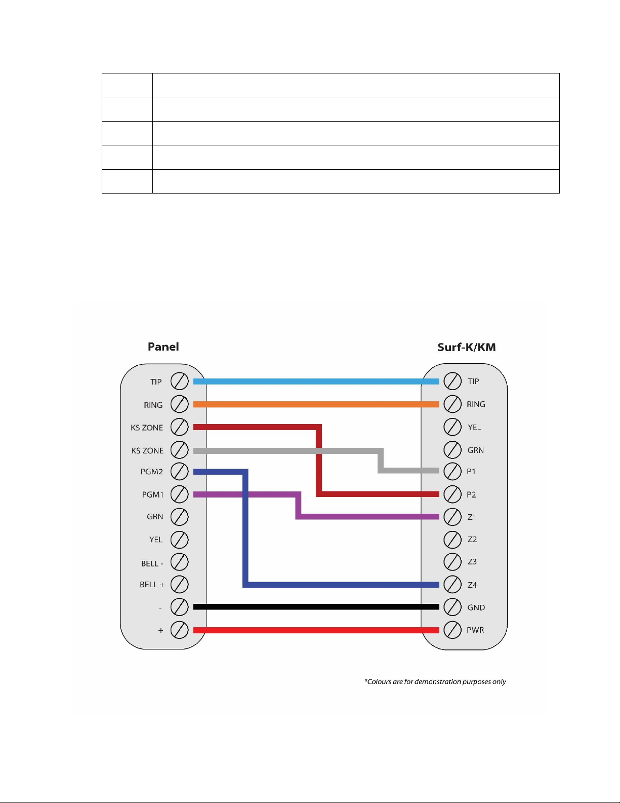
6.2.DSC Alarm Panels
6.2.1.Dial Capture (Tip/Ring) Monitoring and Keyswitch
For DSC panels that do not support keybus use Tip/Ring and keyswitch to monitor and
control your system remotely.
6.2.1.1.Wiring Diagram

19
6.2.1.2.Programming Instructions
To monitor DSC alarm panels with dial capture, program your system as described below.
Instructions in italics are for optional remote arming with keyswitch. PGMs on Surf-K/KM
can be connected to any zone programmed as keyswitch for remote arming functionality.
6.2.1.2.1.ALEXOR (PC9155)
Section
Description
[015]
Turn option 4 on, to enable quick arming, and option 7 off, to disable TLM.
[301]
Enter any phone number.
[310]
Enter a system account number.
[350]
Enter 03 for CID reporting or 04 for SIA.
[351]
Turn option 1 on for alarm/restore reporting.
[367]
Turn option 1 on for open/close reporting.
[380]
Turn option 1 on to enable communicator for digital monitoring.
[381]
Options 3 and 7 must be off for automatic SIA and CID reporting.
[001]
Set a zone to 22 for keyswitch arm.
[009]
Set PGM1 to 05 for partition armed status monitoring.
[023]
Turn on option 8 for keyswitch to arm in Away mode.
[501]
Option 3 must be on to enable true output.
6.2.1.2.2.IMPASSA (SCW9055/9057)
Section
Description
[015]
Turn option 4 on, to enable quick arming, and option 7, to disable TLM.
[301]
Enter any phone number.
[310]
Enter a system account number.
[350]
Enter 03 for CID reporting or 04 for SIA.
[351]
Turn option 1 on for alarm/restore reporting.
[367]
Turn option 1 on for open/close reporting.
[380]
Turn option 1 on to enable communicator for digital monitoring.
[381]
Options 3 and 7 must be off for automatic SIA and CID reporting.

20
[001]
Set a zone to 22 for keyswitch arm.
[009]
Set PGM1 to 05 for partition armed status monitoring.
[023]
Turn on option 8 for keyswitch to arm in Away mode.
[501]
Option 3 must be on to enable true output.
6.2.1.2.3.NEO (HS2016/2032/2064/2128)
Section
Description
[015]
Turn option 4 on, to enable quick arming, and options 7 and 8 off, to disable TLM.
[301]
Enter any phone number.
[310]
Enter a system account number (first entry) and an account number for each
active partition.
[311]-[318]
Turn on option 1 for each partition alarm/restore (first entry) and open/close
(third entry) reporting.
[350]
Enter 03 for CID reporting or 04 for SIA.
[380]
Turn option 1 on to enable communicator for digital monitoring. Option 4 must
be off.
[001]
Set a zone to 66 for keyswitch arm on partition 1 (set another for partition 2).
[007]
Assign PGM1 to partition 1 (PGM2 for partition 2).
[009]
Set PGM1 to 115 for partition 1 armed status monitoring (set PGM2 for partition
2).
[010]
Option 1 must be on for both 001 (PGM1) and 002 (PGM2) subsections, to enable
true output.
[022]
Turn on option 8 for keyswitch to arm in Away mode.
6.2.1.2.4.PC4020 MAXSYS
Section
Description
[0004000000]
Enter any phone number.
[0004000001]
Enter 04 for CID or 05 for SIA format.
[00040003]
Enter a system account number.
[01000100]- [01000800]
Enter an account number for each active partition.
[000401]
Enable “DTMF Dialing”, “AutoReport SIA”, and “Auto Contact ID”
options, and disable “TLM Enabled” option.
[0004000002]
Enable alarm/restore and open/close reporting.
Other manuals for Surf-k
1
This manual suits for next models
1
Table of contents
Other EPIC SAFETY Security System manuals


 Quick installation guide")


