manuals.online logo
Brands
  1. Home
  2. •
  3. Brands
  4. •
  5. Fire-Lite
  6. •
  7. Security System
  8. •
  9. Fire-Lite BG-12LA User manual

Fire-Lite BG-12LA User manual

BG-12LA Manual Pull Station
Document 51381 Revision A ECN 00-215 06/13/2000
Door ‘keys’ into
backplate at this point
12LAdoormount.wmf
1. Position the door and backplate side
by side in the full open position. (i.e.
180-degrees with respect to each
other.)
2. With the backplate position fixed,
move the door behind the backplate,
as shown in the illustration, part A.
3. Align the hinge posts and holes by
bringing the door up to meet the
backplate, paying particular attention
to the ‘keying’ that occurs when the
door’s post hole is aligned to the
backplate’s hinge post. Refer to the
illustration, part B.
4. With the two pieces aligned and
‘keyed’ together, slide the holes
down onto the posts. Refer to the
illustration, part C.
5. Holding the backplate, close the door
slightly to lock the door and backplate
together.
Door Reattachment
If the door becomes detached, complete the following steps to
reattach the door to the backplate. The door cannot be connected
to the pull station if the unit is mounted to a backbox.
Switch Contact Rating
FACP Circuit (Terminals 1 & 2):
Rated to .25 Amp at 30 Volts (AC or DC).
Auxiliary Contact Circuit (Terminals 3 & 4):
Rated to 3 Amps at 30 Volts (AC or DC).
Mounting
Surface mount the BG-12LA pull station to a SB-10 surface
backbox. Semi-flush mount the BG-12LA to a standard single-
gang, double-gang, or 4-inch (10.16 cm) square electrical box.
Dual Action BG-12LA
BG12face.wmf
Description:
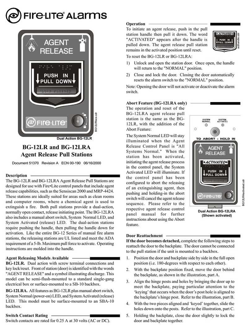
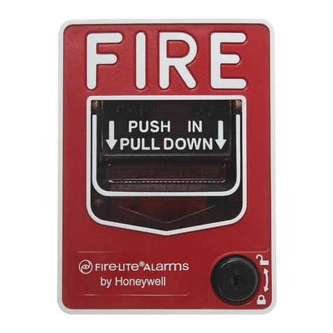
The BG-12LA Pull Station is a non-coded manual pull station
which provides a Fire Alarm Control Panel (FACP) with a single
alarm initiating input signal. The pull station also provides a
second set of contacts rated up to 3 Amps at 30 volts (AC or
DC), for auxiliary functions. The BG-12LA is a dual action
model equipped with a key lock reset. It is UL listed and meets
the ADA requirement of a 5-lb. maximum pull down force to
activate. Operating instructions are molded into the handle.
Molded terminal numbers can also be found adjacent to the
wiring terminals.
With the door and backplate
aligned and ‘keyed’ together,
slide the holes down onto the
posts.
Closing the door slightly
locks the door and
backplate together.
Door mated to Backplate
at this stage.
Post
UL
Product ID
Label
UL
Product ID
Label
Hole
Post
Hole
Post
Document 51381 Revision A ECN 00-215 06/13/2000
Wiring Instructions
1) Before mounting the pull station, pull all necessary wiring
through the backbox.
2) Remove the correct amount of wire insulation. The pull
station’s backplate is molded with a strip gauge to measure
the amount of insulation to be removed.
3) Connect the wiring from the fire alarm control panel’s
Initiating Device Circuit (IDC), or any previous device on
the IDC to terminals 1 and 2 located on the pull station’s
terminal strip. Connect the next device on the IDC or End-
of-Line Resistor (ELR) to terminals 1 and 2. Note: Maintain
consistent polarity with all connections throughout the IDC.
4) Connect the wiring for the normally open (N/O) auxiliary
switch circuit to terminals 3 & 4.
Operation
To activate the dual-action station, first push in the handle, and
then pull the handle down. The handle locks into the activated
position. The word ‘ACTIVATED’ appears after the handle is
pulled down. The pull station remains in the activated position
until reset with the key lock.
1) Reset the BG-12LA by inserting the key into the lock and
turning it ¼ turn (counter-clockwise).
2) Open the door until the handle returns to the ‘NORMAL’
position.
3) Close and lock the door. Closing the door automatically
resets the switch to the ‘NORMAL’ position. Note: Opening
the pull station door will not activate or deactivate the FACP
alarm switch or the auxiliary function switch.
CAUTION
Install the pull station in accordance with the supplied instructions, applicable NFPA standards, national and local Fire and Electrical
codes and the requirements of the Authority Having Jurisdiction (AHJ). Conduct regular testing of the devices using appropriate
NFPA standards. Fire•Lite is not responsible for devices that have not been properly installed, tested or maintained. For ADA
compliance, if the clear floor space only allows forward approach to an object, the maximum forward reach height allowed is
48 inches (121.92cm). If the clear floor space allows parallel approach by a person in a wheelchair, the maximum side reach height
allowed is 54 inches (137.16cm).
BG-12LA Wiring
From FACP
IDC
12345678
1
234567
8
12345678
1234
1
23
4
1234
1234
1234
1234
1
23
4
1234
1234
1
23
4
1234
To Next Device
IDC
Aux. Contact
Aux. Contact
12LAwiring.wmf
BG12activated.wmf
BG-12LA Pull Station
(Shown Activated)

Other Fire-Lite Security System manuals

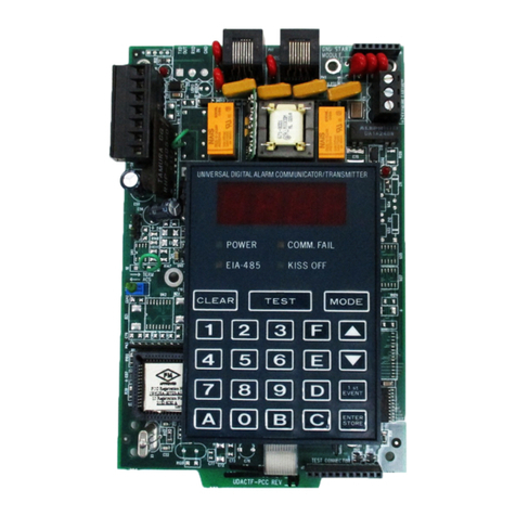
Fire-Lite DACT-UD User manual

Fire-Lite

Fire-Lite DACT-UD User manual

Fire-Lite Fire-Lite Alarms BB-17F Technical manual

Fire-Lite

Fire-Lite Fire-Lite Alarms BB-17F Technical manual

Fire-Lite BG-12LAO User manual

Fire-Lite

Fire-Lite BG-12LAO User manual

Fire-Lite ACM-16ATF User manual

Fire-Lite

Fire-Lite ACM-16ATF User manual

Fire-Lite Device User manual

Fire-Lite

Fire-Lite Device User manual

Fire-Lite BG-12LO User manual

Fire-Lite

Fire-Lite BG-12LO User manual

Fire-Lite MBT-1 User manual

Fire-Lite

Fire-Lite MBT-1 User manual

Fire-Lite BG-12 Series User manual

Fire-Lite

Fire-Lite BG-12 Series User manual

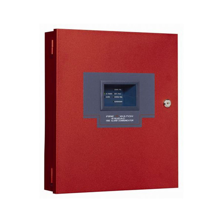
Fire-Lite FireWatch 411UD User manual

Fire-Lite

Fire-Lite FireWatch 411UD User manual

Fire-Lite UDACT-F User manual

Fire-Lite

Fire-Lite UDACT-F User manual

Fire-Lite BG-12LR User manual

Fire-Lite

Fire-Lite BG-12LR User manual

Fire-Lite Fire-Lite Alarms BB-26 User manual

Fire-Lite

Fire-Lite Fire-Lite Alarms BB-26 User manual

Fire-Lite FIRE-LITE 411UDAC Operating instructions

Fire-Lite

Fire-Lite FIRE-LITE 411UDAC Operating instructions

Fire-Lite FireWatch 411UD User manual

Fire-Lite

Fire-Lite FireWatch 411UD User manual

Popular Security System manuals by other brands

U-Prox Keypad MF user manual

U-Prox

U-Prox Keypad MF user manual

AJAX MotionProtect quick start guide

AJAX

AJAX MotionProtect quick start guide

LEXMAN LDSENK14F instruction manual

LEXMAN

LEXMAN LDSENK14F instruction manual

Chuango CG-A11 user guide

Chuango

Chuango CG-A11 user guide

Pandora Pandect X1100 manual

Pandora

Pandora Pandect X1100 manual

Arcteq AQ 200 Series instruction manual

Arcteq

Arcteq AQ 200 Series instruction manual

Lorex LW2710 Series instruction manual

Lorex

Lorex LW2710 Series instruction manual

Secufirst ALM314S quick start guide

Secufirst

Secufirst ALM314S quick start guide

Potter VSA quick start guide

Potter

Potter VSA quick start guide

Meraki MX84-HW installation guide

Meraki

Meraki MX84-HW installation guide

Pentatech DF270 Set operating instructions

Pentatech

Pentatech DF270 Set operating instructions

Profoon PAK-50 Installation and setup

Profoon

Profoon PAK-50 Installation and setup

ADEMCO VISTA-250BP Installation and setup guide

ADEMCO

ADEMCO VISTA-250BP Installation and setup guide

Siterwell GS412B user manual

Siterwell

Siterwell GS412B user manual

Super Circuits SYRF04 Installation and setup guide

Super Circuits

Super Circuits SYRF04 Installation and setup guide

Kidde DM3000 Installation sheet

Kidde

Kidde DM3000 Installation sheet

Visonic SR-720 PG2 installation instructions

Visonic

Visonic SR-720 PG2 installation instructions

Bulldog Security PRO-SERIES 5002 Installation and owner's guide

Bulldog Security

Bulldog Security PRO-SERIES 5002 Installation and owner's guide

manuals.online logo
manuals.online logoBrands
  • About & Mission
  • Contact us
  • Privacy Policy
  • Terms and Conditions

Copyright 2025 Manuals.Online. All Rights Reserved.