E+H Cerabar T PMP 135 Manual
Technical
Information
TI 372P/24/ae Pressure Transmitter
cerabar T PMP 135
Pressure transmitter for hygienic processes
For absolute and gauge pressures up to 500 psi
Flush-mounted process connections with
metal diaphragm
The Power of Know How
Application
The Cerabar T PMP 135 is a pressure
transmitter for hygienic applications, e.g.
in the food processing and pharmaceuti-
cal industries. It is designed for measur-
ing absolute and gauge pressures in
gases, vapors, liquids and dust.
• Finely graduated measuring ranges
up to 500 psi
• Electronic versions include:
- 4 to 20 mA analog output
- Switch output (PNP)
Features and benefits
The PMP 135 is a compact, low cost
pressure transmitter, engineered for
hygienic processes.
• Flush-mounted process connections
with metal diaphragm
• Hygienic design as per 3-A guidelines
• Analog output accuracy ≤0.5%, PNP
switch point deviation ≤1%
• Up to 5 times overload resistant and
excellent longterm stability (0.15%
per year)
• Process temperature, -13° to +212°F;
maximum temperature 275°F (1 hour)
• Optional 3.1.B inspection certificate
• Wetted materials made of 316L SS
with a surface quality of Ra≤0.8 µm
(better than 150 grit)

Cerabar T PMP 135
Endress+Hauser
Function and system design
Measuring principle PMP 135 with analog output
The process pressure acting on the metallic separating diaphragm of the sensor is
transmitted to a resistance bridge via a fill fluid. The change in the output voltage of
the bridge is proportional to the pressure and can be measured directly.
PMP 135 with PNP switch output
The process pressure acting on the metallic separating diaphragm of the sensor is
transmitted to a resistance bridge via a fill fluid. A differential amplifier creates a
standard signal from the pressure-proportional change in the output voltage of the
bridge. A comparator with an adjustable hysteresis compares this signal with the
pre-set switch point and then activates the transistor output and LED display.
Cerabar T PMP 135 pressure transmitter with:
• 4 to 20 mA analog output
Power supply, e.g. RN 221N transmitter power supply unit from Endress+Hauser
• Switch output
Preferably in connection with a programmable logic controller (PLC). Positive
signal at electronics switch (PNP).
Measuring system
Input
The measured variable for the Cerabar T PMP 135 pressure transmitter can be
selected as either gauge or absolute pressure.
Measuring ranges up to 500 psi (40 bar) can be selected (refer to Ordering Informa-
tion).
Measured variable
Measuring range
Output
Output signal 4 to 20 mA
RB≤(US- 12 V) / 0.02 A (US= power supply)
Analog output
Load
2
4 to 20 mA
pp
1
2
AB
A = analog output with transmitter power supply unit 1
B = PNP output with load 2 , e.g. PLC, DCS, relay

Cerabar T PMP 135
Endress+Hauser 3
Output signal Positive voltage signal (rate depends on power supply voltage) at electronics switch
output (PNP)
Switch status ON: Ia≤500 mA
Switch status OFF: Ia≤1 mA
Maximum 6 W
Maximum 10 Hz
Input resistance Ri≤2 kΩ
Input current Ii≥10 mA
To prevent electrical interference, only operate an inductive load (relays, contactors,
solenoid valves) when directly connected to a protective circuit (diode or capacitor).
Switch (PNP) output
Output current
Power
Switch frequency
Input PLC
Inductive loads
Power supply
Cable entry
1/2” NPT or PG 11 M 12 x 1 plug 15 ft cable, analog output only
1 Plug-in housing 1 Coupling nut 1 Reference pressure line
2 Plug-in jack with gasket 2 Connector with gasket
3 Coupling nut 3 Operating potentiometer (inner)
4 Plug with o-ring
5 Operating potentiometer (inner)
1
2
11
2
3
3
4
5
1/2" NPT / Pg 11 M 12x1 16 ft (5 m) cable

Cerabar T PMP 135
Endress+Hauser
4
Electrical connection
Analog output connection
Supply voltage 12 to 30 VDC
Maximum 5%
Plug with 1/2” NPT, Pg 11, M 12 x 1 or cable
Residual ripple
Cable entry
1 Plug with 1/2” NPT or Pg 11
2 M 12 x 1 ;lug
3 Cable (rd = red, wh = white, gn = green
1 Plug with 1/2” NPT or Pg 11
2 M 12 x 1 ;lug
R: External load, e.g. relay, programmable logic controller, distributed control system
PNP switch connection
Supply voltage
Residual ripple
Cable entry
Current consumption
12 to 32 VDC
Without load, < 20 mA, with reverse polarity protection
Maximum 10%
Plug with 1/2” NPT, PG 11 or M 12 X 1
––
–
++
+
+
GND
–
12
3
rd
wh
gn
3
3
2
1
12 to 30 V
12 to 30
V
12 to 30 V
4 to 20 mA
4 to 20 mA
4 to 20 mA
2 –
1 +
–
–
+
+
2 –1+ 3+
R
R
12
18 to 32 V
3
2
1

Cerabar T PMP 135
Endress+Hauser 5
Performance characteristics
Note: Percentages listed below refer to the measuring range
As per DIN IEC 60770, T = 77°F (25°C)
≤0.5% including hysteresis and non-reproducibility (limit point method as per
DIN IEC 60770)
≤1%
≤0.5%
2 to 4 ms
≤0.15% per year
• Zero: typical 0.2% / 10K, maximum 0.5% / 10K. Values are 0.1% / 10K higher for
measuring spans ≤87 psi (6 bar)
• Span: typical 0.2% / 10K, maximum 0.5% / 10K
• Switch point: typical 0.2% / 10K, maximum 0.5% / 10K
Reference operating conditions
Analog output non-linearity
Switch point deviation
Switch point non-reproducibility
Settling time
Long-term drift
Influence of temperature
Operating conditions, installation
Any orientation. Orientation dependent zero shift can be corrected using potentiom-
eter adjustments
Mounting position
Operating conditions, environment
-13° to +158°F (-25° to +70°C)
-40° to +185°F (-40° to +85°C)
4 Z: with Z = 158°F (70°C) as per VDI/VDE 3540
• NEMA 4X (IP 65) with 1/2” NPT or Pg 11 cable entry
• NEMA 4X (IP 65) with M 12 x 1 plug, when using gauge pressure sensors
NEMA 6P (IP 68), 1 m water column, with 12 x 1 plug, when using absolute
pressure sensors
• NEMA 6P (IP 68), 1 m water column, with cable
4M5 as per DIN EN 60721-3
Interference emission as per EN 61326 electrical device B
Interference immunity as per EN 61326 appendix A (industrial use) and NAMUR
recommendation NE 21
Ambient temperature
Storage temperature
Climate class
Degree of protection
Vibration resistance
Electromagnetic compatibility
Operating conditions, process
-13° to +212°F (-25° to +100°C), maximum 275°F (135°C) for maximum 1 hour
Maximum overload resistance, refer to “Ordering information”
Vacuum resistance up to 0.14 psia (10 mbarabs)
Medium temperature
Limiting medium pressure range

Cerabar T PMP 135
Endress+Hauser
Mechanical construction
PMP 135 dimensions
A = height dimension of process connector (see process connection drawings below)
• Plug version with 1/2” NPT or Pg 11 cable connection per DIN 43650A/ISO 4400
• M 12 x 1 plug version
• Cable version , with 16 ft. (5 m) fixed cable including pressure compensation
tube.
Process connections
Tri-clamp, 1/2” or 3/4” (ISO 2852)
Tri-clamp, 1” or 1-1/2” (ISO 2852)
Tri-clamp, 2” (ISO 2852)
G 1A (ISO 228), with tapered metallic seal
G 1A (ISO 228), with sealing surface for flush-mounted installation
SMS 1-1/2”
1
2
3
4
5
6
6
1/2" NPT / Pg 11 M 12 16 ft
(5 m) cable
3.11"
(79)
1.46"
(37)
2.05"
(52)
3.11"
(79)
0.59"
(15)
2.72"
(69)
2.13"
(54)
1.53"
(39)
AAA
Ø 1.08"
(27.5) Ø 1.08"
(27.5) Ø 1.08"
(27.5)
123
456
G1A
G1A Ø 2.17"
(55)
1.30"
(33) * 1.30"
(33) * 1.30"
(33) *
1.30"
(33) *
1.54"
(39) * 1.61"
(41) *
1.06"
(27) 0.91"
(23)
Ø 1.08"
(27.5)
Ø 1.34"
(34)
Ø 1.71"
(43.5)
Ø 1.99"
(50.5)
Ø 2.22"
(56.5)
Ø 2.52"
(64)
MMM
M
M
M = diaphragm diameter,0.68" (17.2 mm)
* = "A" dimension height added for overall unit length (refer to graphic at top of page).
M

Cerabar T PMP 135
Endress+Hauser
Human interface
Materials • Process connections and diaphragm: 316L SS
Wetted surface smoothness: Ra≤0.8 µm (≥150 grit)
• Transitter housing: 304 SS
• Plug: polyamide (PA)
• Cable outer covering: polyurethane (PUR)
• Fill fluid: Neobee M20 (FDA-no. 21CFR172.856)
Operating elements location
The potentiometer for operating the
Cerabar T with analog or PNP switch
output is located beneath the plug base.
Operating elements
Adjustments Analog output: zero point adjustment
The zero point can be adjusted for the Cerabar T with analog output and plug
version.
PNP switch output: switch point and hysteresis adjustment
The Cerabar T with PNP switch output allows adjustment of both the switch point and
hysteresis. Adjustment can be made at atmospheric pressure using the enclosed
test cables and voltmeter.
1
Potentiometer for zero point correction by ± 5% of the measuring range
1
Hysteresis adjustment, 1.5 to 20%; factory setting 10%
2
Switch point adjustment, 0 to 100%; factory setting 50%
3
LED color code for checking switch status: green = OFF; red = ON
4
Connect voltmeter to test points: 0 to 1 V corresponds to 0 to 100%
Percentages refer to the measuring range.
7
1
+
–
1
2
3
4

Cerabar T PMP 135
Endress+Hauser
8
Instructions for switch point and hysteresis
U
out
= output voltage
p = acting pressure
The percentages refer to the measuring range
Hysteresis
1.5 to 20 %
Switch point
0 to 100 %
ON = red LED
OFF = green LED
Switch
on Switch
off
p
Uout
on
off
Certificates and approvals
CE mark By attaching the CE mark, Endress+Hauser confirms that the instrument fulfills all the
requirements of the relevant EC directives.
This device conforms to Article 3 (3) of EC Directive 97/23/EC (pressure equipment
directive) and is developed and produced in sound engineering practice.
Pressure equipment directive

Cerabar T PMP 135
Endress+Hauser 9
Ordering information
Cerabar T PMP 135 PMP 135 -
1 Electrical connection
A1 Plug with Pg 11 cable gland, NEMA 4X (IP 65)
A2 Plug with 1/2” NPT conduit entry, NEMA 4X (IP 65)
A3 Cable, 16 ft. (5 m), NEMA 6P (IP 68)
A4 M 12 x 1 plug, NEMA 4X (gauge) / NEMA 6P (absolute) (IP 65 / 68)
2 Process connection
F Tri-clamp, 1/2” to 3/4”
G Tri-clamp, 1” to 1-1/2”
H Tri-clamp,2”
M G 1A, with metallic sealing, tapered
N G 1A with sealing surface for flush-mounted installation
S SMS1-1/2”
3 Output signal, certificate
0 4 to 20 mA analog, 2-wire
2 PNP switch output, 3-wire
4 Additionalequipment
1 Withoutadditionalequipment
C 3.1.B inspection certificate per EN 10204
2 Linearity protocol
5 Measuringrange(permitted overload)
Gaugepressure
Q4H 0 to 15 psi (60 psi)
Q4K 0 to 30 psi (150 psi)
Q4N 0 to 50 psi (240 psi)
Q4R 0 to 150 psi (600 psi)
Q4S 0 to 300 psi (1500psi)
Q4T 0 to 500 psi * (2400 psi)
A1G 0 to 1 bar / 0 to 100 kPa (4 bar)
A1H 0 to 1.6 bar / 0 to 160 kPa (6.4 bar)
A1N 0 to 2.5 bar / 0 to 25 kPa (10bar)
A1Q 0 to 4 bar / 0 to 400 kPa (16bar)
A1R 0 to 6 bar / 0 to 600 kPa (24 bar)
A1S 0 to 10 bar / 0 to 1000 kPa (40bar)
A1T 0 to 16 bar / 0 to 1600 kPa (64bar)
A1W 0 to 25 bar / 0 to 2500 kPa (100 bar)
A1X 0 to 40 bar * / 0 to 4000 kPa * (160bar)
* absolute pressure transmitter
Absolutepressure
R4H 0 to 15 psi (60 psi)
R4K 0 to 30 psi (150 psi)
R4N 0 to 50 psi (240 psi)
R4R 0 to 150 psi (600 psi)
R4S 0 to 300 psi (1500 psi)
R4T 0 to 500 psi (2400 psi)
A2G 0 to 1 bar / 0 to 100 kPa (4 bar)
A2H 0 to 1.6 bar / 0 to 160 kPa (6.4 bar)
A2N 0 to 2.5 bar / 0 to 25 kPa (10bar)
A2Q 0 to 4 bar / 0 to 400 kPa (16bar)
A2R 0 to 6 bar / 0 to 600 kPa (24 bar)
A2S 0 to 10 bar / 0 to 1000 kPa (40bar)
A2T 0 to 16 bar / 0 to 1600 kPa (64bar)
A2W 0 to 25 bar / 0 to 2500 kPa (100 bar)
A2X 0 to 40 bar / 0 to 4000 kPa (160bar)
1 2 3 4 5
Cerabar T PMP 135
Endress+Hauser
10
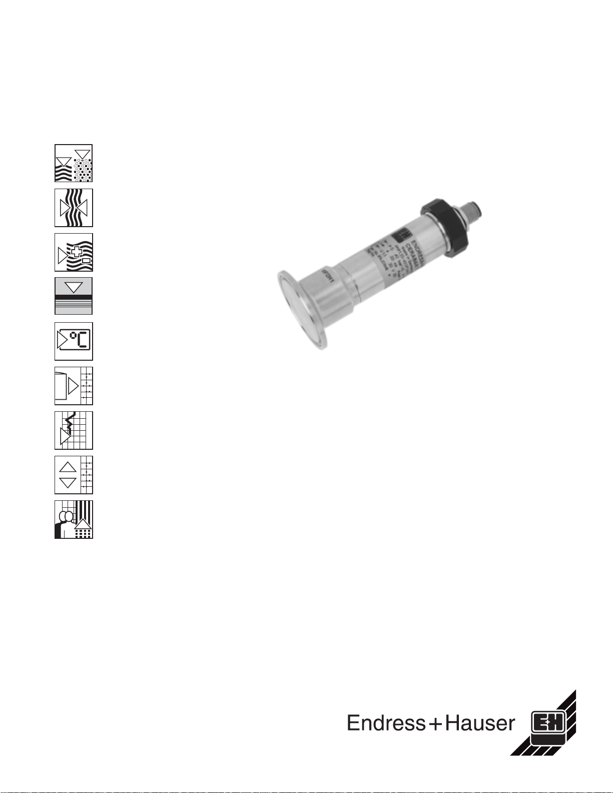
Accessories
Welding bosses • Welding boss for flush-mounted
installation of G1 A process
connection with metallic sealing
taper (used with process connection
M selection, order code).
Material: 316L SS
Order number: 52005087
• Optional with 3.1.B inspection
certificate
Order number: 52010171
1.97"
(50)
1.18"
(30)
• Welding boss for flush-mounted
installation of G1 A process
connection with sealing surface
(used with proces connection N
selection, order code).
Material: 316L SS
Gasket (enclosed): silicon o-ring
Order number: 52001051
• Optional with 3.1.B inspection
certificate
Order number: 52011196
• Welding aid (dummy plug) for welding
the boss (order numbers 52005087
and 52001051), prevents warping
of boss during welding.
Material: brass
Order number: 52005272
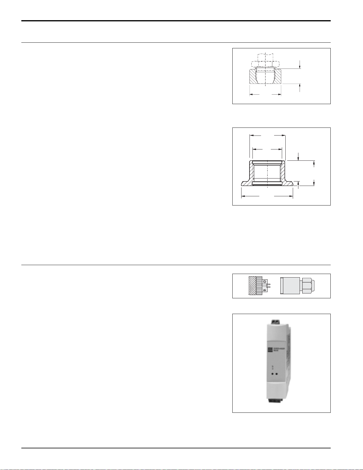
• M 12 x 1 plug-in jack, connection to
M 12 x 1 housing
Order number: 52006263
ø 2.36"
(60 )
-0 . 0 1 5
– 0 . 4
0.97"
(24.6) 1.17"
(29.6)
ø 1.61"
(41)
G1
ISO 228
Plug-in jack
Power supply / display units • RN 221 N transmitter power supply
unit. For safe galvanic isolation of the
4 to 20 mA analog signal and for
supplying power to the Cerabar T.
Refer to TI 073R/09/en

Cerabar T PMP 135
Endress+Hauser 11
• RIA 251 process display unit, digital
display unit for indicating the analog
signal through the 4 to 20 mA current
loop.
Refer to TI 063R/24/ae
Supplemental documentation
Cerabar T PMP 131, pressure transmitter with
polysilicon sensor: TI 291P/24/ae
Cerabar T PMC 131, pressure transmitter with
capacitive ceramic sensor: TI 279P/24/ae
PMP 135 operation/installation manual: KA 198P/00/a6

UnitedStates
Endress+Hauser, Inc.
2350 Endress Place
Greenwood,IN46143
Phone:(317)535-7138
888-ENDRESS
FAX:(317)535-8498
TI372P/24/ae/03.03
© 2002 Endress+Hauser, Inc.
Canada
Endress+Hauser
CanadaLtd.
1440Graham’sLane
Unit 1, Burlington
ON,L7S 1W3
Phone:(905)681-9292
800-668-3199
FAX:(905)681-9444
Mexico
Endress+Hauser
Paseodel Pedregal No. 610
Col.Jardines del Pedregal
01900, Mexico D.F.
Mexico
Phone:(525)568-2405
FAX:(525)568-7459
For application and selection assistance,
in the U.S. call 888-ENDRESS
For total support of your installed base, 24 hours
a day, in the U.S. call 800-642-8737
Visit us on our web site, www.us.endress.com
Endress+Hauser
The Power of Know How
Table of contents
Popular Transmitter manuals by other brands

HBC-Radiomatic
HBC-Radiomatic spectrum 1 M operating instructions

BEKA
BEKA BA474ND Installation & maintenance instructions

Nice
Nice DTX600 Instructions and warnings for installation and use

PCS Electronics
PCS Electronics TVMAX 8000U+ manual

XtremeMac
XtremeMac Airplay Boost user manual

Eddystone Broadcast
Eddystone Broadcast S7600 Series Installation and operations


