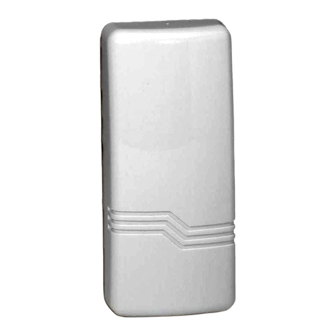
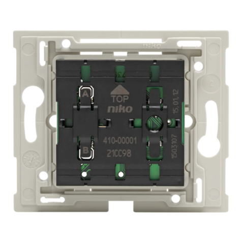
Nexta Tech MCU-TX4 User manual

Radio control, rolling code, 433.92 MHz, 4 channels
with inputs for wall buttons.
Dual power-supply: mains 120-240 VAC or battery CR 2032
MCU-TX4
3.1 TRANSMITTER PROGRAMMING
Once the wired buttons are connected, the controller behaves like a generic type of transmitter. In order to be able to use
it, it must be programmed on a compatible receiver
PROCEDURE:
1- Activate the receiver on which you want to use the transmitter in "radio programming of generic transmitters" mode
and select the function that you want to associate with the key (see receiver manual).
2- Press the desired wired button, the receiver's LED flashes 3 times to signal it has been received.
MNLMCU-TX4ENV1.1
3 - RADIO PROGRAMMING
Nexta Tech
company brand of Team srl
via G.Oberdan 90, 33074
Fontanafredda (PN) - Italy
Ph. +39 0434 998682
Web: www.nexta-tech.com
INDEX
1 - PRODUCT FEATURES
1.1 - TECHNICAL DATA
1.2 - DESCRIPTION
2 - ELECTRICAL CONNECTIONS
2.1 - BATTERY POWER SUPPLY
2.2 - GRID POWER SUPPLY
3 - RADIO PROGRAMMING
3.1 - TRANSMITTER PROGRAMMING

1.2 DESCRIPTION
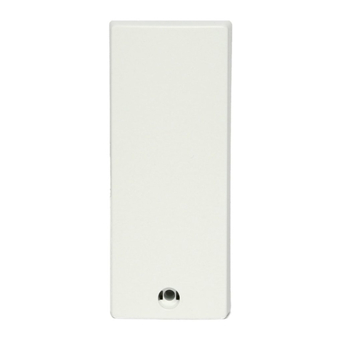
Recessed remote control with 4 channels, ideal for transforming wired wall buttons into radio controls.
The innovative dual power supply, either from the mains or a battery, means it can be installed on wire-controlled
units or on pre-existing sensors. The ISM (industrial, scientific and medical) radio frequency band guarantees a long
range, even through walls and ceilings. Ultra-reduced dimensions with breakable tabs for fixing with screws or for
insertion into connection boxes 55 mm in diameter.
1 PRODUCT FEATURES
2 ELECTRICAL CONNECTIONS
43mm
21mm 52mm
Led
58mm
1.1 TECHNICAL DATA
Mains 120-240 VAC or
CR 2032 battery
4
433,92MHz
120 m in free field
IP20
-20 +55 °C
52X43X21
Power supply
Number of TX channels Radio
frequency
Range
Protection rating
Operating temp.
Dimensions
2.1 BATTERY POWER SUPPLY
With this type of connection the battery must be inserted into the plastic casing.
WARNING: It is possible to connect multiple buttons to the same input with parallel connection.
2.2 GRID POWER SUPPLY
WARNING: It is possible to connect multiple buttons to the same input with parallel connection.
WARNING: If the transmitting controller is powered from the grid, the battery should not be inserted.
The transmitting controller can be powered from the grid or by battery. The battery life varies depending on different
factors, but it can be estimated at an average of about four years.
WARNING: If the transmitting controller is powered from the grid, the battery should not be inserted.
Fig.2.1
Fig.2.2
Fig.1.1 Button
Fig.1.1b Fig.1.1c
- Installation must be carried out only by qualified technicians in compliance with the electrical and safety standards in
force.
- All connections must be made with the power turned off.
- Use suitable cables.
- Do not cut through the aerial (see figure 1.1b)
- A suitably sized disconnection device must be set up on the electric power line that supplies the product.
- Disposal of waste materials must fully respect local standards.
WARNINGS
N
L
P1 P2 P3 P4
maximum distance =
3m
1 2 3 4 5 6 7
P1 P2 P3 P4
maximum distance=
3m
1 2 3 4 5 6 7

Radio control, rolling code, 433.92 MHz, 4 channels
with inputs for wall buttons.
Dual power-supply: mains 120-240 VAC or battery CR 2032
MCU-TX4
3.1 TRANSMITTER PROGRAMMING
Once the wired buttons are connected, the controller behaves like a generic type of transmitter. In order to be able to use
it, it must be programmed on a compatible receiver
PROCEDURE:
1- Activate the receiver on which you want to use the transmitter in "radio programming of generic transmitters" mode
and select the function that you want to associate with the key (see receiver manual).
2- Press the desired wired button, the receiver's LED flashes 3 times to signal it has been received.
MNLMCU-TX4ENV1.1
3 - RADIO PROGRAMMING
Nexta Tech
company brand of Team srl
via G.Oberdan 90, 33074
Fontanafredda (PN) - Italy
Ph. +39 0434 998682
Email: [email protected]
Web: www.nexta-tech.com
INDEX
1 - PRODUCT FEATURES
1.1 - TECHNICAL DATA
1.2 - DESCRIPTION
2 - ELECTRICAL CONNECTIONS
2.1 - BATTERY POWER SUPPLY
2.2 - GRID POWER SUPPLY
3 - RADIO PROGRAMMING
3.1 - TRANSMITTER PROGRAMMING
Table of contents

