PCS Electronics TVMAX 8000U+ User manual


I M P O R T A N T N O T E
Upon receiving your order inspect the packaging material and unit for apparent damage.
Any damage should be reported immediately so we can make a claim with the shipping
company. Take photos, if you can, they can be used as proof.
IMPORTANT! If you want to connect an amplifier to this exciter, please first make sure that
output power is set correctly and does not exceed maximum allowable input power of the
amplifier. See appendix for additional tips on driving amplifiers.
If you are buying an exciter module always bolt the board into a metal enclosure and use a
suitable fan to always cool it.
Study local regulations and ensure you are operating in compliance!
Never ever operate any exciter/transmitter or amplifier without a properly tuned
load/antenna!

Brought to you by PCS Electronics, www.pcs-electronics.com
Table of Contents
Introducing CyberMaxTV+ and TVMAX8000+ modules............ 3
What makes this TV transmitter so great? ...................................... 3
What is the DSP Stereo Encoder for USA/NTSC?.......................... 3
Antenna options .............................................................................. 3
How is TVMAX8000V+ better than TVMAX 6000V+....................... 3
Quick Technical specifications ........................................................ 4
Thank you for purchasing CyberMaxTV+ / TVMAX8000+ .............. 4
TVMAX8000+ and LCD boards layouts ..................................... 5
RF board layout .............................................................................. 5
LCD module layout – 3 keys model................................................. 7
LCD module layout – rotary encoder model.................................... 8
Before you start ........................................................................ 11
Antenna......................................................................................... 11
SWR – antenna matching ............................................................. 12
BNC connector.............................................................................. 12
Mains power supply and mains power cable................................. 12
Audio source with mixer, microphone etc...................................... 12
Enclosure and cooling for MAX PRO 8000+ series exciters ......... 12
How to wire everything together and use TVMAX8000+......... 14
Wiring things up and first power-up............................................... 14
Using the TVMAX8000+ or CyberMaxTV+ ................................... 14
Troubleshooting ............................................................................ 15
Using the TVMAX 8000+ series exciter ................................... 16
LCD control module – two types ................................................... 16
<RF POWER> .............................................................................. 16
Changing frequency...................................................................... 17
<VIEW SELECT>.......................................................................... 17
<SHOW TEST PIC>...................................................................... 17
<TV STANDARD>......................................................................... 17
<SOUND CARRIER>.................................................................... 18
<LCD CONTRAST>...................................................................... 18

Brought to you by PCS Electronics, www.pcs-electronics.com
<PIC TO SOUND>........................................................................ 18
<WHITE CLIP> ............................................................................. 18
<PLL STEP> ................................................................................. 18
<FIRMWARE VER> ...................................................................... 19
<BAND SELECT>......................................................................... 20
<RF POWER ALC>....................................................................... 20
Appendix A – Frequency tables ............................................... 21
Frequency tables (HAM RADIO).............................................. 23
Appendix B – IO board and PC remote control ....................... 24
Software installation...................................................................... 24
Configuring communications port.................................................. 25
Installing USB driver (only for USB IO board) ............................... 26
Configuring USB driver ................................................................. 26
Appendix C – Warranty and legal info ..................................... 28
Important notice! ........................................................................... 28
Warranty and servicing! ................................................................ 28
Legal info ...................................................................................... 28
Limitation of liability....................................................................... 28
Also available from www.pcs-electronics.com .............................. 29
Revisions and errata ................................................................ 30
Index......................................................................................... 31

Brought to you by PCS Electronics, www.pcs-electronics.com
Introducing CyberMaxTV+ and TVMAX8000+ modules
Finally affordable VHF/UHF TV transmitters
hird generation of our analog TV transmitters is finally out, bringing all the bells and whistles that our FM
broadcasting line had for a long time. This is your ticket into the world of TV. Build your own TV studio and
broadcast your own TV program! Transmit movies from your PC to your living room, re-transmit the TV
program you've never been able to receive in your valley, run a college TV station, cover rural areas of Africa with
TV signal from satellite TV stations, run a hotel cable system info pages or just have fun; this unit will keep you busy during
the cold winter evenings and is sure to provide lots of fun for many months to come!
What makes this TV transmitter so great?
TVMAX8000V+ supports all existing analog TV standards and all existing analog TV sound standards. It includes a simple
built-in test signal generator. Unit is available either as a populated and tested board or a 1H rack-mounted ready-to-use
transmitter with built in mains power supply, which is then called CyberMaxTV+. Boxed unit runs from mains, the module
requires 24-48V DC. An optional stereo encoder board is also available and provides stereo sound. Up to 7W of output
power offers from several hundred meters up to about 5km of range depending on antenna type used on both transmitting
and receiving side. High gain Yagi antennas on both sides might offer even more range in favorable conditions. The unit
was designed for 24/7/365 operation. Each unit has a wide-angle high contrast backlit LCD display. Output power and TV
channel can be adjusted via LCD display.
What is the DSP Stereo Encoder for USA/NTSC?
This add-on card enables stereo sound, it was designed for NTSC system, used in USA and most of South/North America.
Check our website for prices and availability.
Antenna options
We have provided suitable antennas and coaxial cable with connectors, check our website for more info. Yagi antennas are
perfect for 2-way transmission from one point to the other.
How is TVMAX8000V+ better than TVMAX 6000V+
- More output power due to new linear output stage
- Maxlink audio input connector
- Can be setup with the on-board DIP switches (LCD not necessary)
- Better image quality, especially in VHF model
- Frequency is now freely adjustable, PLL step is 125KHz for VHF and 250KHz for UHF, HAM radio ATV band is fully
covered
- Support for external Power/Swr meter via DIGIAMP connector, perfect for building larger 100W/500W/1000W TV
transmitters
- Works directly off 28-50V so you can power the amplifier and the exciter from the same power supply!
- Full remote control via PC possible via USB, COM port or even Ethernet!
Chapter
1
T

Brought to you by PCS Electronics, www.pcs-electronics.com
Quick Technical specifications
- Supports PAL/SECAM/NTSC (all analog world standards) Note SECAM is not available in DIP switch mode
- Supports all sound standards (4.5-6.5MHz, adjustable)
- Output power VHF model: 10W (typically about 7-12W for VHF band III and 5-15W for band I and II), adjustable from
0 to max via LCD menu system when using LCD display
- Output power UHF model: 7W (typically about 8W around 470MHz decreasing to under 1W at 850MHz), adjustable
from 0 to max via LCD menu system
- Audio connectors: RCA (cinch)
- Audio level: 1Vpp
- Video level: 1Vpp
- Audio input impedance: 10K resistive, unbalanced
- Pre-emphasis 50 or 75µSec (adjustable with a jumper, installed jumper = 75µS)
- TV Channels VHF model: VHF BAND I, II & III, 41-83MHz and 175-225MHz (VHF LO and VHF HI)
- TV Channels UHF model: Entire UHF band, 470MHz to 855MHz in 250KHz steps (expandable on request), also
supports radio amateur band 421-440MHz in 125KHz steps
- Output impedance 50 Unbalanced, VSWR less than 2:1 for full output
- Output connector BNC female (rear panel)
- Modulation type: DSB, occupies close to 2x the standard TV channel space, add notch filter for full compliance
- Monitoring Led: Power on
- Harmonic distortion (THD) <0,1% typ.
- Stereo Channel Separation 25 dB min 20Hz to 15kHz (NTSC stereo only)
- Voltage power supply DC 24-48V/1.5A
- Built-in CPU for controlling and monitoring
- Easy changing of frequency (LCD with UP/DOWN keys or DIP switch) and other parameters
- Stereo sound possible (with plug-in board for USA or extra board for other countries)
- Friendly user interface
- Cost effectiveness
- Board size 100x125mm
- Standard 19" rack 1HE high
- External rack dimensions (W x D x H ) 19" x depth (170mm) x height 1HE (44mm)
- Weight rack 3kg, board 0.3kg
Thank you for purchasing CyberMaxTV+ / TVMAX8000+
We hope you will enjoy it as much as we do and remember to tell your friends about it. Please feel free to leave your
comments at our website or post your experience in our forum. From all of us we wish you happy broadcasting!
Your PCS Electronics team


Brought to you by PCS Electronics, www.pcs-electronics.com
Ref.
Function
S Connect ON/OFF switch here, but you can also just install a jumper. A LED diode can also be connected as
shown on the image, series resistor for the diode is on board and is not necessary.
8 MaxlinkII connector for easy connection with the optional Audio Input board which adds 2xRCA inputs, 2x
XLR inputs and USB audio input.
5 Pre-emphasis. Use this jumper to set pre-emphasis. This can either be 50uS (EU and most of the world) or 75uS
(USA). If you plan to connect stereo encoder to the MAXPRO8000+ board, place the jumper in position None
(bottom - this disables pre-emphasis).
1 Video input – RCA or video coaxial cable
2 Audio input – RCA or audio microphone cable
7 Digiamp connector enables easy control of RF amplifiers. This greatly simplifies the process of building FM
transmitters. You can read more about this connector in this manual. The flat cable is non-crossed type.
13 Internal power meter accuracy adjustment. If the internal power display on the LCD is a bit off you can correct its
accuracy with this trimmer. You have to “reboot” to verify the setting as the power detector has some DC offset
which is measured once when the unit powers up.
6 To 6-pin IO BOARD header on IO remote control board. Connects two BNC connectors from IO board to
VIDEO and AUDIO input.
10 VU bar graph meter. Connect the 3-pin jumper to VU meter here. It will show audio. Another 5-pin header for
VU meter is available next to LCD connector and carries power for display and SWR and PWR from internal
power meter.
S Posts for a small 12V or 48V fan. The output stage appreciates a bit of air flow.
3 LCD control unit, attach your LCD control module here. The flat cable used is crossed.
P Power supply connector if barrel type than center is positive. DO NOT use more than 15V for 8015/8025.
R RF output connection. BNC jack. Use a properly matched antenna. The range and success of your transmissions
will depend primarily upon the quality and position of your antenna.
F Fuse F2A
X Remote stand-by, you can put unit in standby by closing/shorting these two pins. The power will go to zero
immediately. These two pins are at the bottom of header D.
4 Optional NTSC stereo encoder board connects here. When using this board connect audio to solder posts 9
below the board.
D Power range jumper J10, use to set output power range to 0-1W,0-2W, 0-3W, 0-4W or any other range all the way
to 0-15W. No jumpers = full power
B Bias adjustment for output stage
Table 1: Description of various elements of the TVMAX8000+ TV exciter board


Brought to you by PCS Electronics, www.pcs-electronics.com
Reference Function
1, F UP key
2, G DOWN key
3, H MENU key
4, B POWER indicator LED. Illuminated whenever you turn on the exciter.
5, C ERROR indicator LED. This LED is activated when RF output stage is NOT active. For example,
whenever if temperature protection is activated, this LED illuminates and RF power is reduced.
Important: This LED is also illuminated whenever you change frequency as the control unit turns RF
power off until adjustments are finished and VCO is locked. In such case this does not signal a problem
with temperature or SWR.
6,7 Mounting screws, M2.5 metric screw is to be used here.
8 LCD module, with backlight
A 14-pin connector for flat cable going to the RF board
D Microcontroller with software
E, L Connections to the IO board (RS232, USB) for remote control
I ALC enable, soldering this together lets you set power limit (ALC). Also lets you set band in STL model.
K You can disable keys by cutting the lead between the two pads between the “Lock Keys
” solder bridge. If
you want to re-enable the keys, solder the two pads “Lock Keys” back again. You can also connect a lock
-
switch here.
+LED- You can connect the LED diode here (usually used for the on/off switch.
Table 2: Description of various elements of the LCD display module
LCD module layout – rotary encoder model
Let us have a quick look at, note you can disable keys by cutting the lead between the two pads in the “Lock Keys” solder
bridge. If you want to re-enable the keys, solder the two pads “Lock Keys” back again.
Fig. 4: LCD module layout, front and back, rotary encoder version 2x16

Brought to you by PCS Electronics, www.pcs-electronics.com
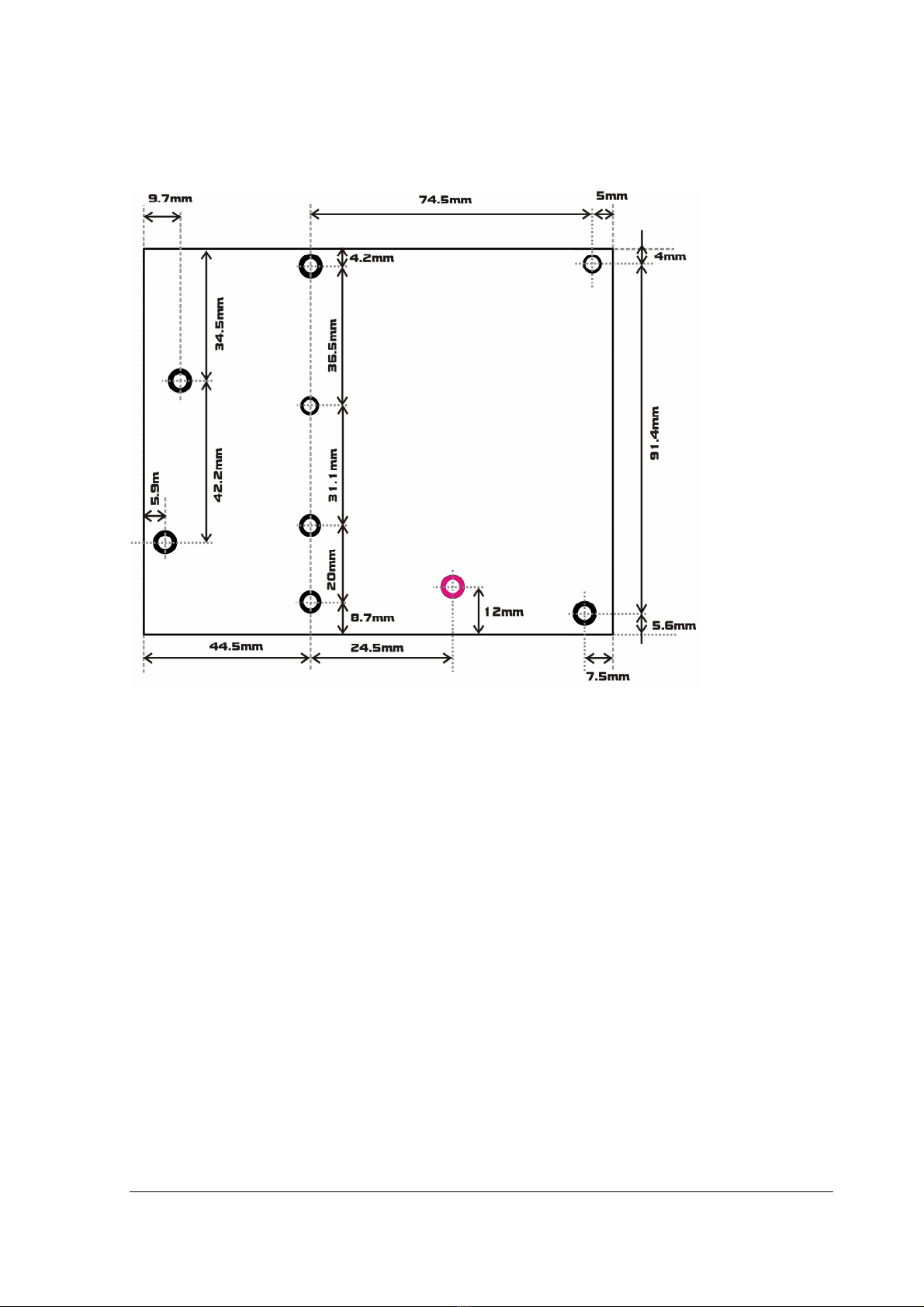
Fig. 8: RF module drill template for TVMAX8000, all measurements in mm, all holes are for M3
metric screws. Board is 10mm above the enclosure due to heat sink running under the entire width of
the board. A few holes may need to be checked, the pink one is definitely not needed.

Brought to you by PCS Electronics, www.pcs-electronics.com
Before you start
It is recommended that you read this section before you power your unit up for the first time. Let us clear up some basics
you should know about. You will also find some useful tips in our guides and forum at http://www.pcs-electronics.com.
Here is what you need to get your TV transmitter on the air:
Antenna
Preferred type of antenna is affected by several factors, but mostly by desired radiation pattern, space available and your
budget. If you are in the middle of the area you want to cover, you'll need an omni-directional antenna which transmits
equally in all directions. If you are located at the edge of your desired coverage area you can beam the signal into the target
area with a directional antenna. Directional antennas are also practical for point-to-point communications. Another thing to
consider is that directional antennas usually have much higher gain than omni-directional antennas since the power which is
radiated in all directions with omni antenna is concentrated mainly into one direction with directional antenna. Antennas
with more gain thus have narrower beam. A compromise is usually made depending on budget and space available, higher
gain antennas are often bigger and often more expensive.
Once you’ve chosen and installed your antenna there is another thing to consider. You can read more about it in the next
section (So what is this SWR everyone talks about). Before powering up your transmitter on the air you should tune your
antenna to get minimal SWR. This is typically done by adjusting the position of the antenna and any adjustable pieces. Aim
for 2:1 or less. Use low power into the antenna when tuning it up and adjusting. If you were using full power and a bit of the
antenna came off in your hand the VSWR could be so bad as to blow the final transistor. For the same reason check the
DC continuity of the antenna with an ohmmeter before plugging it in, to be sure it's what it's meant to be, either a short
circuit or an open one, depending on the antenna type. For instructions regarding construction of antennas please see our
website: http://www.pcs-electronics.com (guides section - antennas).
Antenna is a crucial part of the system so take special care. It is usually a good idea to place the antenna away from your
transmitter, power supply and audio system. Also, any transmitter should be in a metal case which shields circuitry from the
radiation of the antenna. If you cannot meet these requirements, you could experience feedback and other RF problems.
We cannot guarantee proper operation of any transmitter/amplifier unless a suitable antenna system is used, and
transmitters are in ventilated metal enclosure! This applies to any transmitter. Interestingly, strong RF field can make CD
players and other digital devices literally go crazy. Try placing an antenna next to yours and see what happens. Most of the
modern audio gear is not RF shielded – reducing costs is unfortunately the mantra today. This is why keeping antenna away
from audio gear is a good idea, too.
If you are going to place your antenna outside, on your roof, please take care of the grounding. This should be done to
prevent lightning hazards and should be done by a company specializing in lightning protection. You can read more about
lightning protection in the book recommended below or many of the websites (google up “lightning protection ham radio”
for example).
I hope this basic introduction will not scare you too much, it should be sufficient for the time being although we encourage
you to explore this exciting subject further with the help of a book such as the ARRL Antenna Book:
https://www.amazon.com/exec/obidos/ASIN/1625951116/mightyspiraterad
Chapter
3

Brought to you by PCS Electronics, www.pcs-electronics.com
SWR – antenna matching
SWR is a measure of how well two devices are impedance matched to each other. Typical radio/TV transmission
equipment is designed for 50-ohm load impedance, so we usually use 50 ohm cables and build or buy antennas that are
specified for 50 ohm. While most cables have flat impedance over frequency (they measure 50 ohm at all frequencies you
are likely to use) the same is not true of the antennas. A 1.0:1 VSWR is a perfect match. That means the load impedance is
exactly 50 ohms. A 2.0:1 VSWR is obtained when the load impedance is either 25 ohms or 100 ohms. The pro way to go
around these things is to just use antenna analyzer and check performance. RigExpert AA-230 does the job beautifully.
Antenna is a crucial part of the system so take special care. It is usually a good idea to place antenna well away from your
transmitter, power supply, projector and audio system. Placing antenna close to other electronics could cause RF problems
such as audio artifacts, unexpected resetting and locking-up of electronics and other problems, even damage to equipment.
We cannot guarantee proper operation of any transmitter unless a suitable antenna system is used! This applies to any
transmitter. Much of the modern audio/video gear is not RF shielded – reducing costs is unfortunately the mantra today.
This is why keeping antenna away from gear is a good idea.
Please take care also of the grounding. This should be done to prevent lightning hazard since you’re putting up antenna
tower.
Coaxial cable
Coaxial cabling is commonly found in broadcast and networking systems. Most coaxial cables have a characteristic
impedance of either 50 or 75 ohms. The RF industry uses standard type-names for coaxial cables. The U.S military uses the
RG-# or RG-#/U format (probably for "radio grade, universal", but other interpretations exist).
Most broadcasting antennas and transmitters, including ours, are 50 ohms. Don't buy more than you need to make the long
run to your antenna and don't make up a few "jumpers" to go between your exciter, VSWR meter and your antenna as all
you'll do is create higher SWR and more line losses and potential weak contact spot. Belden H-155 (shorter runs) or H2000
(longer runs) are good choices for up to 20-25m!
BNC connector
A connector comes between coaxial cable and your transmitter. It’s a standard VHF RF connector for low power
applications, just like the one used for older Ethernet networks. You might get it along with your antenna. Try to find a
good quality BNC connector as PC type usually uses cheap plastic instead of Teflon. The good ones are usually easily
recognized by higher prices. Another reliable method is a test with soldering iron; Teflon won’t melt while plastic will. BNC
to N or BNC to SO239 converters are available and will make it possible to connect N or PL259 (CB type or UHF)
connector directly.
Mains power supply and mains power cable
Do not underestimate the importance of mains power supply, despite the abundance of all kinds of cheap units available
today they unfortunately do not always meet requirements. What you need is a well stabilized DC 15V mains power supply
that can supply at least 5 amps of continuous current without overheating, introducing buzzing, dropping the voltage down
to 12V or lower (a classic case) or acting up in other way. Whenever in doubt please buy our mains power supply. One final
note, our units are set for 15V and if you use less this may lower your output power a bit. Supply voltage less than 15V may
result in slightly reduced output power.
If you ordered and received our mains power supply (which is recommended) you’ll notice the mains cable is not included,
but can be obtained in any radio/computer/hardware shop at the cost of about 1 US$. It is the type used in your PC for
mains power. Since these cables vary from country to country and we had trouble getting the exact type locally we decided
against including them, especially since finding them is so easy locally.
Audio source with mixer, microphone etc.
You need some kind of audio source to drive your transmitter. This will typically be either a computer (just plug the cable
into your sound card outputs, a mixer and a variety of audio sources, such as a microphone, CD player, DAT player, tape
deck, gramophone, MP3 player etc.
Enclosure and cooling for MAX PRO 8000+ series exciters

Brought to you by PCS Electronics, www.pcs-electronics.com
Use metal (preferably aluminum) for your enclosures and allow some free space for future add-ons (stereo encoders etc.)
and heat dissipation, also make ventilation holes at the top and/or back of the enclosure. Fix the PCB and heat-sink with all
screws tightly. Read again, ALL screws. Make sure they make good contact with the metal enclosure and if there is paint
remember to remove it under the distancers. Use metal distancers, not plastic. Flat cable should be wired away RF sections
or if you are not sure where that is move it away from the board in general. A fan is needed, 40x40x25mm will run quietly,
you can connect it to the provided pads which also regulate fan speed according to output power. Make sure you tightly
screw the RF board to the enclosure as this is how the output transistor dissipates its heat! Since 25W is quite a lot
of power it is important that you follow these guidelines. If you still experience instability, make sure there are metal shields
between compartments in your enclosure. You can also brush off the black anodizing off the heat sink where the heat sink
meets the enclosure and board to ensure better contact. Anodizing creates an isolating layer. You can remove that also for
the top heat sink where it meets the board.

Brought to you by PCS Electronics, www.pcs-electronics.com
How to wire everything together and use TVMAX8000+
Wiring things up and first power-up
Wiring the TVMAX8000+ or CyberMaxTV+ is easy, just make sure you read the previous chapter first and set up antenna,
coaxial cable, and mains power supply correctly. Then proceed with the following:
- The board (if you purchased your unit without enclosure) should be mounted inside a metal enclosure. Metal serves as a
large heatsink for the output transistor and ensures cooling and electromagnetic shielding. A small fan is recommended!
- Connect your 50ohm antenna (tuned) to the antenna connector (BNC) at the back. If you have SWR/POWER meter,
wire that one inline as well. Make sure it supports the frequency band set via LCD display or DIP switch (VHF and correct
channel).
- Connect audio/video signals to audio and video RCA jacks (VIDEO and AUDIO on PCB or at the back of 1H rack).
- Connect mains power supply into the power jack at the back.
- Flip the switch and wait for the unit to turn on, enter the menu system by pressing the bottom key and set TV channel
frequency, TV standard & audio standard for your country and tune your TV receiver to the same TV channel. Select a free
TV channel that is not occupied. The two neighboring channels should be free as well for best results and minimal
interference. You can use a built-in test signal generator to verify operation. This signal produces a beep on the sound carrier
and vertical BW bars like your VCR setup test signal.
- If needed, set the output power higher or better yet to the minimum needed (to prevent unneeded interference). Power
can be adjusted via LCD module with up/down keys.
Using the TVMAX8000+ or CyberMaxTV+
Here are some additional tips and valuable info related to using TVMAX8000V+ or CyberMaxTV+:
- There are three push-buttons available on the front panel. The top two are UP and DOWN while the third one at the
bottom is used to invoke MENU. You can change any of the available settings by pushing the UP or DOWN button
inside any of the available menus.
- Green LED on the LCD module is always lit and signals power on. RED led is lit when the unit is either overheating or
there is SWR alarm problem (antenna matching problem detected).
- Stereo operation requires stereo encoder. If you want stereo sound for PAL/SECAM or NTSC, please purchase an
appropriate stereo encoder. It is best that you buy tv transmitter and stereo encoder together (preferably the rack box
version) so we can wire these together for you saving you trouble.
- The on-board trimmers should not be touched unless you have substantial experience and know what you’re doing and
own suitable test equipment to verify operation, you can read more about these trimmers in the following sections of this
manual.
- Sufficient cooling is crucial for optimum output power and long life, a fan is necessary and must always be active. Unit
starts powering down if it overheats. It is thus of utmost importance that you mount this transmitter into a metal enclosure
and bolt the output stage heatsink to the enclosure and use a small fan.
Chapter
4
Brought to you by PCS Electronics, www.pcs-electronics.com
Troubleshooting
We hope you’ll never get to this step. We all know bad things happen but do not despair! First, TVMAX8000+ is protected
with a fuse and TEMP protection. Fuse is the first thing to check. Make sure your coaxial cable leading to the transmitter
and antenna is not shorted or open. Next check the troubleshooting table below. If you have problems, you cannot solve
yourself, please see our website for contact information and support resources in our forum.
PROBLEM DESCRIPTION
POSSIBLE SOLUTIONS
Unit produces very poor range 1. Check power supply, is it 24V? Less? Get another power supply. 48V are needed to get full output
power.
2. Is the unit running very hot? Mount it into metal enclosure and use a fan to cool it.
3. Check coaxial cable and connectors
4. Check antenna
5. You can try to tune trimmers for more output power, but this requires power/swr meter.
Unit keeps showing I2C error 1. Make sure all DIP switches are in the OFF position
Power is always set to full
(can’t reduce power via LCD display)
1. Make sure jumper J10 is not installed
Unit is very hot, and its output fell to zero If you take extremely poor care of cooling (no metal enclosure, no fan of any kind) it will eventually
become hot and reduce output power. In normal operation, the unit typically runs at 60-70 degrees
Celsius max. Please ensure proper cooling and unit will stop shutting off.
Unit blows fuses and draws excessive
current
You have managed to burn the output transistor. You've probably tried to squeeze out too much
output power by increasing the bias voltage. You may have used more than 48V supply voltage. It is
time to order a replacement final transistor and get the soldering iron. Next time think twice about
doing these things.
Power supply is blinking Probably the same thing as above. Blinking power supply means its protection is shutting it off and
back on, probably due to excessive current draw caused by burned final.
Repetitive noise/sound can be heard on the
radio.
1. Check your antenna and cable, you have a serious SWR problem, SWR protection is kicking in.
Usually there is a short on your coaxial cable or antenna.
Audio too quiet - Increase audio level on your source (VCR, DVD player, satellite receiver etc).
There is HUM in audio - Get a proper mains power supply, stabilized type!
- Move antenna as far away from the transmitter and audio gear as possible
- Make sure SWR is low
- Form a coil from coaxial cable going to the antenna, make a few turns. This stops RF currents that
might be flowing on the outer braid of the coaxial cable. This usually happens when you connect
unbalanced cable to balanced antenna without proper BALUN (balanced-unbalanced converter)
resulting in coaxial cable becoming part of the antenna and radiating RF energy as well…causing hum.
Figure 9: So, do you think you can handle it? We think you sure can!
Brought to you by PCS Electronics, www.pcs-electronics.com
Using the TVMAX 8000+ series exciter
LCD control module – two types
The basic LCD display is controlled with 3 keys. The advanced display is equipped with a rotary encoder instead. Basically,
with the keys there are three push-buttons available for the menu system: UP, DOWN and MENU. By pushing UP or
DOWN you get a shift of frequency in corresponding direction. Hold any of these keys for a few seconds and the jumps
will increase. The new frequency is saved automatically. The third button (MENU) gives you an option to select and set up
many of the options of this unit. Note that for most users setting frequency and power are the two important/useful
settings, leave the rest alone at default. The default setting is usually depicted with [D].
Units with rotary encoder have the same menu system. The only difference is that for UP and DOWN you must rotate the
knob in the corresponding direction. For MENU you must push the rotary button. Everything else is the same.
LCD control module menu system
The UP and DOWN keys are used to change parameter values. In normal mode the LCD simply shows the frequency and
power or whatever view you select. Menu key can be used to enter the menu mode, repeatedly pressing this key brings up
the following menus: <FREQUENCY>, <SHOW TEST PIC>, <VIEW SELECT>, <TV STANDARD>, <SOUND
CARRIER>, <PIC TO SOUND>, <WHITE CLIP>, <SWR ALARM>, <TEMP ALARM>, <LCD CONTRAST>,
<PLL STEP>, <BAND SELECT>, <SET PASSWORD>, <FIRMWARE VER>, <RF POWER ALC >. Pressing the
UP or DOWN key selects the desired parameter and allows you to modify its value. Another press on the MENU key and
you’re back to the normal mode. Note that all these settings except power and frequency are already set as they should be so
changing them should not be necessary and is not recommended.
<RF POWER>
Select desired power with the UP/DOWN keys at any time. Selected power is displayed on the LCD as a line of bars. Think
of this setting as an accelerator (gas) pedal in your car. Think of the power in watts that is shown on the LCD as the speed
meter in your car. Depending on the road going uphill or downhill speed meter will show different values even if your
accelerator pedal is fixed in the same position. If you go downhill your speed will be greater with the same amount of gas
pedal. Likewise, here your supply voltage can affect the actual output power slightly. After changing power, the LCD display
will go back to primary display mode (view 0) and after a while it will revert back to the view which you selected manually.
Note: UP/DOWN keys change power also when you have set a view type which does not show frequency, such as
UPTIME.
Fig. 10: Setting power, the power is set to full here
Chapter
5
Brought to you by PCS Electronics, www.pcs-electronics.com
Changing frequency
Press the MENU key or rotary button to enter menu system, select [Frequency] menu system. Simply press the
UP/DOWN button to change frequency. Depending on PLL STEP setting your frequency will go down in smaller or
larger steps. If you keep pressing a key for a while the PLL STEP switches to fast tuning mode and jumps inlarger steps.
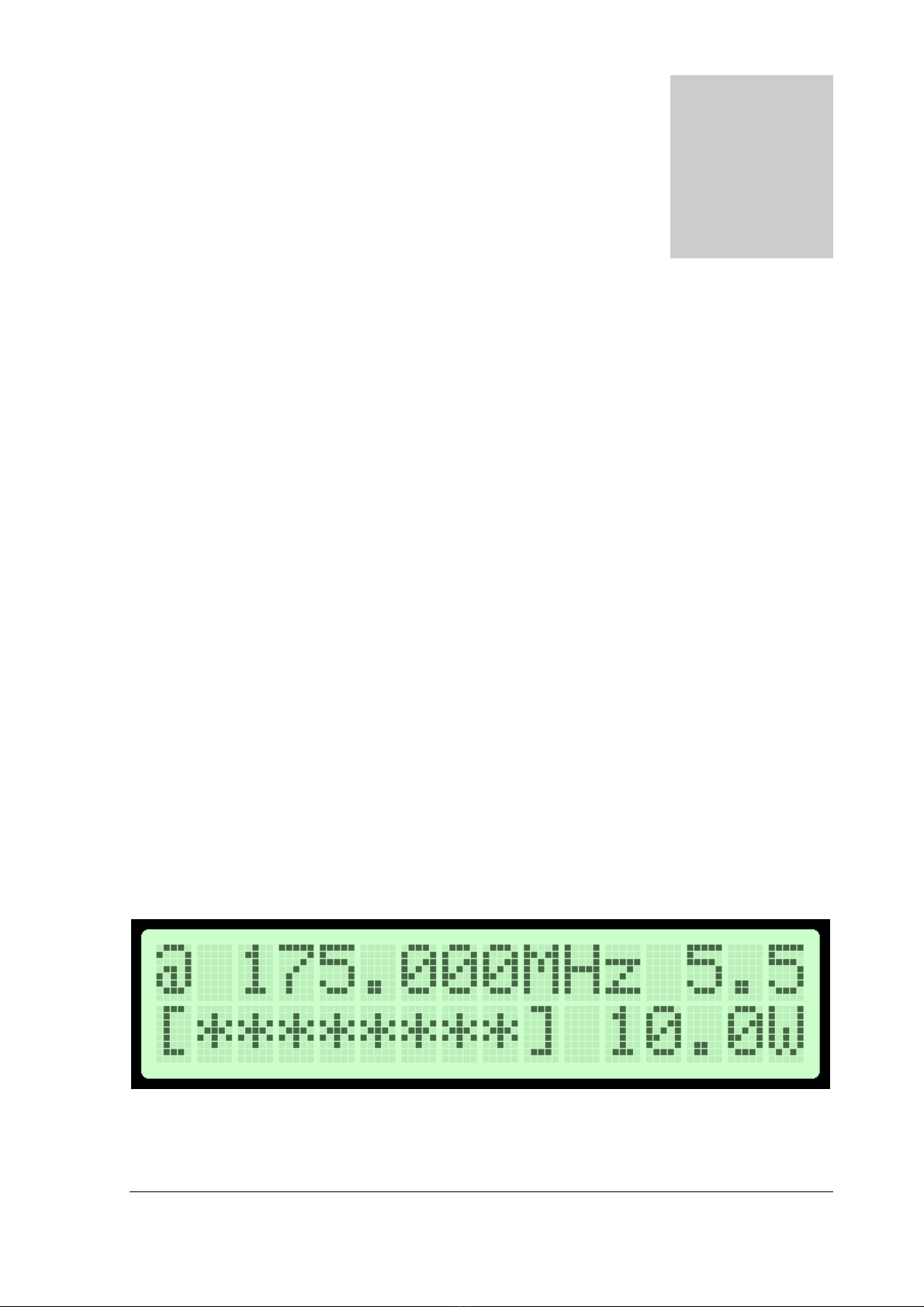
Fig. 11: Setting frequency and power, the power is set to 100% here, sound carrier is at 5.5MHz
<VIEW SELECT>
TVMAX8000+ can display several various parameters. Since the LCD real-estate is limited to 2x16 characters we prepared
several pre-programmed views that only show a selected number of parameters.
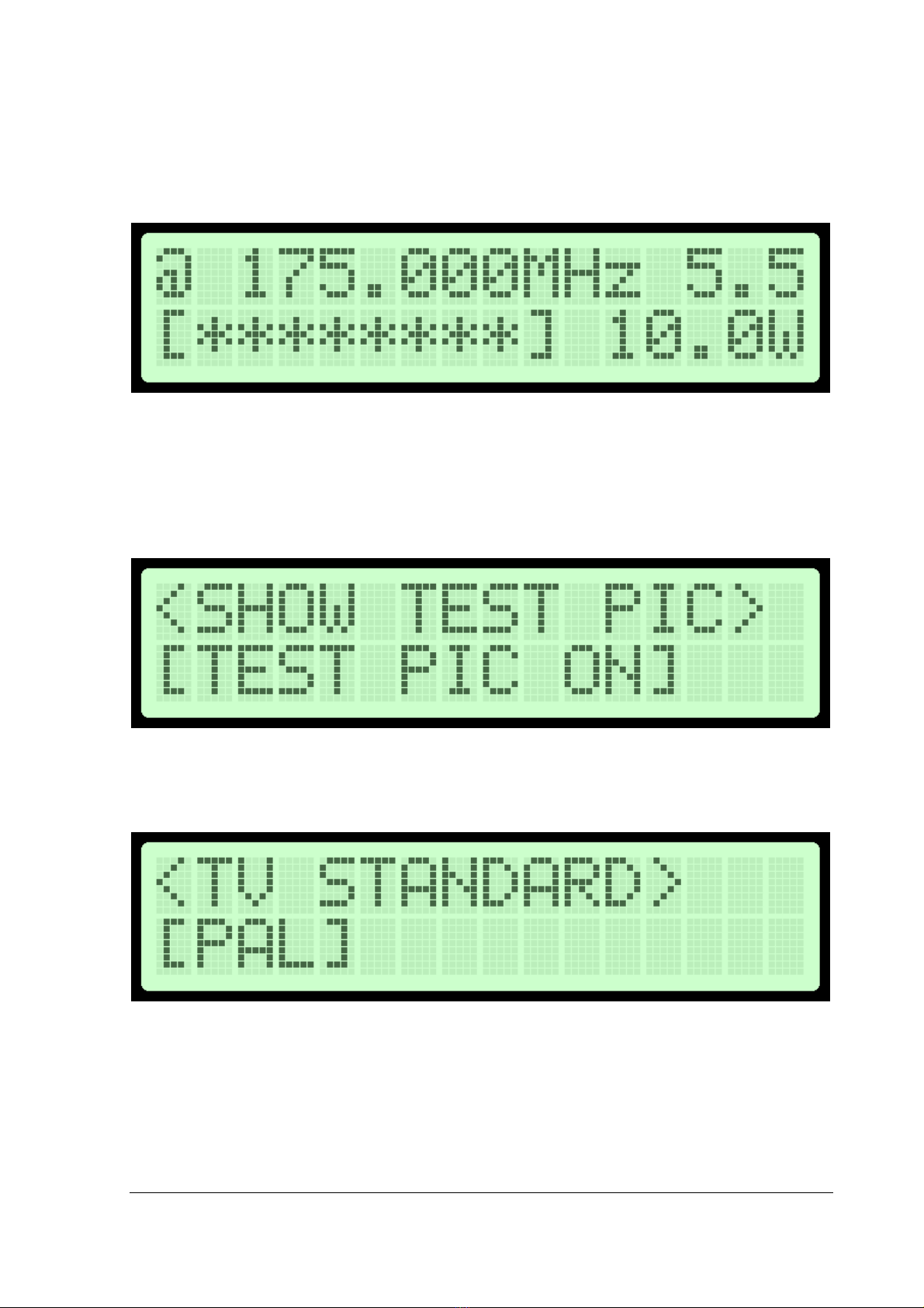
<SHOW TEST PIC>
This option turns on the test image with test beep so you can easily find your program on the TV.
Fig. 12: Setting test PIC on or off.
<TV STANDARD>
This option lets you select TV standard. SECAM, NTSC and PAL are available. Note your video signal source must also be
set to this standard!
Fig. 13: Setting the TV standard.
Brought to you by PCS Electronics, www.pcs-electronics.com
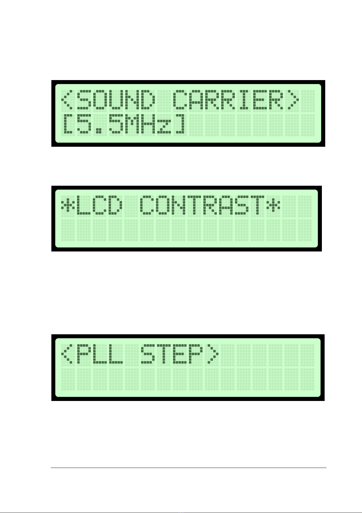
<SOUND CARRIER>
This option lets you select TV sound carrier. 4.5 to 6.5MHz are available. This setting varies from region to region and you
should check what is used locally.
Fig. 14: Setting the TV standard
<LCD CONTRAST>
Select for the best visibility. Contrast is slightly affected by ambient temperature and you can adapt it to your needs here.
Fig. 15: Changing contrast
<PIC TO SOUND>
This option allows you to precisely adjust the modulation ratio between picture and sound. Usually this does not influence performance much,
but you can experiment with this setting.
<WHITE CLIP>
This option allows you to precisely adjust the white clipping level. Usually this does not influence performance much, but you can experiment
with this setting.
<PLL STEP>
Frequency can normally be adjusted in the smallest steps or larger steps. Their size can be selected here.
Fig. 16: Changing PLL frequency steps
This manual suits for next models
2
Table of contents
Other PCS Electronics Transmitter manuals


Popular Transmitter manuals by other brands


M-system
M-system M3LU2 operating manual

Endress+Hauser
Endress+Hauser Levelflex M FMP45 operating instructions

Beck
Beck 985V Series manual

Panametrics
Panametrics DigitalFlow XGM868i Programming manual

Optical Systems Design
Optical Systems Design OSD9003 Operator's manual

AKG
AKG Microtools WMS40 User instructions


