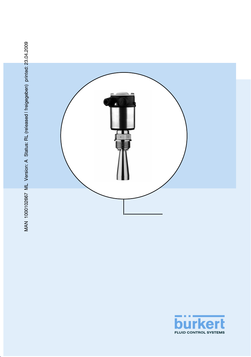
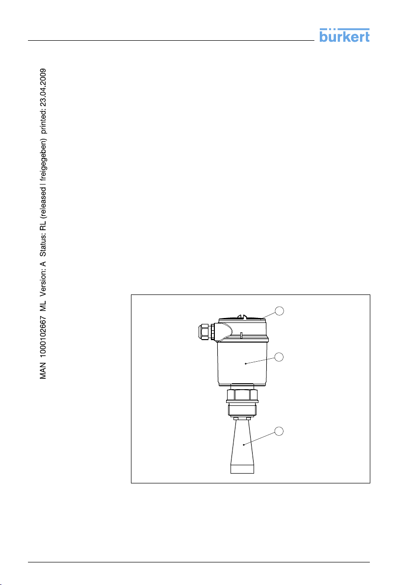
Burkert 8137 User manual

Operating Instructions
LEVEL TRANSMITTER
8137
4 ... 20 mA/HART

Contents
1About this document
1.1Function.................................. 4
1.2Target group .............................. 4
1.3Symbolism used............................ 4
2For your safety
2.1Authorised personnel ........................ 5
2.2Appropriate use ............................ 5
2.3Warning about misuse ....................... 5
2.4General safety instructions . . . . . . . . . . . . . . . . . . . . 5
2.5Safety approval markings and safety tips . . . . . . . . . . 6
2.6CE conformity ............................. 6
2.7Compatibility according to NAMUR NE 53 . . . . . . . . . 6
2.8SIL conformity ............................. 7
2.9FCC/IC conformity (only for USA/Canada) . . . . . . . . . 7
2.10 Safety instructions for Ex areas . . . . . . . . . . . . . . . . . 7
3Product description
3.1Configuration .............................. 8
3.2Principle of operation ........................ 9
3.3Operation................................. 9
3.4Packaging,transport and storage ............... 10
4Mounting
4.1General instructions ......................... 11
4.2Mounting preparations -Horn antenna . . . . . . . . . . . . 12
4.3Mounting preparations -Parabolic antenna. . . . . . . . . 13
4.4Mounting instructions ........................ 14
5Connecting to power supply
5.1Preparing the connection ..................... 21
5.2Connection procedure........................ 22
5.3Wiring plan,single chamber housing . . . . . . . . . . . . . 23
5.4Switch on phase............................ 24
6Set up with the indicating and adjustment module
6.1Short description ........................... 25
6.2Insert indicating and adjustment module. . . . . . . . . . . 25
6.3Adjustment system .......................... 27
6.4Setup procedure............................ 28
6.5Menu schematic............................ 34
6.6Saving the parameter adjustment data. . . . . . . . . . . . 36
7Setup with PACTware and other adjustment programs
7.1Connecting the PC .......................... 37
7.2Parameter adjustment with PACTware . . . . . . . . . . . . 37
7.3Parameter adjustment with AMS™and PDM . . . . . . . 38
7.4Saving the parameter adjustment data. . . . . . . . . . . . 38
2LEVEL TRANSMITTER 8137 •4... 20 mA/HART
Contents
32065-EN-081121

8Maintenance and fault rectification
8.1Maintenance .............................. 39
8.2Remove interferences........................ 39
9Dismounting
9.1Dismounting steps .......................... 41
9.2Disposal ................................. 41
10 Supplement
10.1Technical data ............................. 42
10.2Dimensions ............................... 48
Supplementary documentation
Information:
Supplementary documents appropriate to the ordered version come
with the delivery.You can find them listed in chapter "Product
description".
LEVEL TRANSMITTER 8137 •4... 20 mA/HART 3
Contents
32065-EN-081121

1About this document
1.1Function
This operating instructions manual provides all the information you
need for mounting,connection and setup as well as important
instructions for maintenance and fault rectification.Please read this
information before putting the instrument into operation and keep this
manual accessible in the immediate vicinity of the device.
1.2Target group
This operating instructions manual is directed to trained qualified
personnel.The contents of this manual should be made available to
these personnel and put into practice by them.
1.3Symbolism used
Information,tip,note
This symbol indicates helpful additional information.
Caution:If this warning is ignored,faults or malfunctions can
result.
Warning:If this warning is ignored,injury to persons and/or serious
damage to the instrument can result.
Danger:If this warning is ignored,serious injury to persons and/or
destruction of the instrument can result.
Ex applications
This symbol indicates special instructions for Ex applications.
lList
The dot set in front indicates a list with no implied sequence.
àAction
This arrow indicates a single action.
1Sequence
Numbers set in front indicate successive steps in a procedure.
4LEVEL TRANSMITTER 8137 •4... 20 mA/HART
1About this document
32065-EN-081121

2For your safety
2.1Authorised personnel
All operations described in this operating instructions manual must be
carried out only by trained specialist personnel authorised by the plant
operator.
During work on and with the device the required personal protective
equipment must always be worn.
2.2Appropriate use
LEVEL TRANSMITTER 8137 is a sensor for continuous level
measurement.
You can find detailed information on the application range in chapter
"Product description".
Operational reliability is ensured only if the instrument is properly used
according to the specifications in the operating instructions manual as
well as possible supplementary instructions.
For safety and warranty reasons,any invasive work on the device
beyond that described in the operating instructions manual may be
carried out only by personnel authorised by the manufacturer.Arbitrary
conversions or modifications are explicitly forbidden.
2.3Warning about misuse
Inappropriate or incorrect use of the instrument can give rise to
application-specific hazards,e.g.vessel overfill or damage to system
components through incorrect mounting or adjustment.
2.4General safety instructions
This is a high-tech instrument requiring the strict observance of
standard regulations and guidelines.The user must take note of the
safety instructions in this operating instructions manual,the country-
specific installation standards as well as all prevailing safety
regulations and accident prevention rules.
Depending on the model,the emitting frequencies of all radar sensors
are either in the Cor Kband range.The low transmitting power lies far
below the internationally permitted limit values.When the instrument is
used correctly,it presents no danger to human health.It may be
operated without restriction outside of closed metallic vessels.
The instrument must only be operated in a technically flawless and
reliable condition.The operator is responsible for trouble-free
operation of the instrument.
LEVEL TRANSMITTER 8137 •4... 20 mA/HART 5
2For your safety
32065-EN-081121

During the entire duration of use,the user is obliged to determine the
compliance of the required occupational safety measures with the
current valid rules and regulations and also take note of new
regulations.
2.5Safety approval markings and safety tips
The safety approval markings and safety tips on the device must be
observed.
2.6CE conformity
The protection goals of the EMC Directive 2004/108/EC (EMC), the R
&TTE directive 1999/5/EC and the Low Voltage Directive 2006/95/EC
(LVD)are fulfilled.1)
Conformity has been judged according to the following standards:
EMC:EN 61326-1:2006
(electrical instruments for control technology and laboratory use -EMC
requirements)
lEmission:Class B
lSusceptibility:Industrial areas
R&TTE
I-ETS 300-440 Expert opinion No.0043052-02/SEE,Notified Body No.
0499
LVD:EN 61010-1:2001
(safety regulations for electrical measurement,control and laboratory
instruments -part 1:General requirements)
2.7Compatibility according to NAMUR NE 53
With regard to compatibility,the NAMUR recommendation NE 53 is
fulfilled.This applies also to the corresponding indicating and
adjustment components.
The parameter adjustment of the basic sensor functions is independ-
ent of the software version.The range of available functions depends
on the respective software version of the individual components.
The software version of LEVEL TRANSMITTER 8137 can be
determined as follows:
lon the type label of the electronics
lvia the indicating and adjustment module
1)R&TTE-Richtlinie 1999/5/EC:Not with version with increased sensitivity.
6LEVEL TRANSMITTER 8137 •4... 20 mA/HART
2For your safety
32065-EN-081121

2.8SIL conformity
LEVEL TRANSMITTER 8137 fulfills the requirements for functional
safety according to IEC 61508/IEC 61511.You can find further
information in the Safety Manual "LEVEL TRANSMITTER 813X-
4…20 mA/HART".
2.9FCC/IC conformity (only for USA/Canada)
LEVEL TRANSMITTER 8137 with all antenna versions is FCC/IC
approved.
Modifications not expressly approved by Bürkert will lead to expiry of
the operating licence according to FCC/IC.
LEVEL TRANSMITTER 8137 is in conformity with part 15 of the FCC
directives and fulfills the RSS-210 regulations.Note the corresponding
regulations for operation:
lThe instrument must not cause any interfering emissions
lThe device must be insensitive to immissions,including those that
may cause undesired operating conditions.
The instrument is designed for operation with an antenna according to
chapter "Dimensions"of this operating instructions manual,or without
antenna,with a max.amplification of 33 dB.The instrument must not
be operated with antennas not listed therein or those having an
amplification of more than 33 dB.The required antenna impedance is
50 Ω.
2.10 Safety instructions for Ex areas
Please note the Ex-specific safety information for installation and
operation in Ex areas.These safety instructions are part of the
operating instructions manual and come with the Ex-approved
instruments.
LEVEL TRANSMITTER 8137 •4... 20 mA/HART 7
2For your safety
32065-EN-081121

3Product description
3.1Configuration
The scope of delivery encompasses:
lLEVEL TRANSMITTER 8137 radar sensor
lDocumentation
-this operating instructions manual
-Safety Manual "Functional safety according to IEC 61508
(SIL)"
-Operating instructions manual "Indicating and adjustment
module"(optional)
-Ex-specific"Safety instructions"(with Ex-versions)
-if necessary,further certificates
LEVEL TRANSMITTER 8137 consists of the following components:
lHorn or parabolic antenna
lprocess fitting (depending on the version flange or thread)
lHousing with electronics
lHousing cover,optionally available with indicating and adjustment
module
The components are available in different versions.
2
3
1
Fig.1:LEVEL TRANSMITTER 8137 -threaded version with plastic housing
1Housing cover with integrated indicating and adjustment module (optional)
2Housing with electronics
3Process fitting with horn antenna
The type label contains the most important data for identification and
use of the instrument:
Scope of delivery
Components
Type label
8LEVEL TRANSMITTER 8137 •4... 20 mA/HART
3Product description
32065-EN-081121

lArticle number
lSerial number
lTechnical data
lArticle numbers documentation
3.2Principle of operation
LEVEL TRANSMITTER 8137 is a radar sensor in K-band (emitting
frequency approx.26 GHz)for continuous level measurement.
Asuitable version of LEVEL TRANSMITTER 8137 is available for each
area of application:
The version with "thread and horn antenna with ø40 mm (1.575 in)"
is particularly suitable for small tanks and process vessels for
measurement of virtually all products.
The version with "Flange and horn antenna with ø48 …95 mm
(1.89 …3.74 in)"is particularly suitable for storage tanks and process
vessels,for measurement of products such as solvents,hydrocarbons
and fuels under most difficult process conditions.
The version with "Parabolic antenna"is particularly suitable for
precise measurement of products with small dielectric figure.
The antenna of the radar sensor emits short radar pulses with a
duration of approx.1ns.These pulses are reflected by the product
and received by the antenna as echoes.The running time of the radar
pulses from emission to reception is proportional to the distance and
hence to the level.The determined level is converted into an
appropriate output signal and outputted as measured value.
Two-wire electronics 4…20 mA/HART for power supply and
measured value transmission over the same cable.
The supply voltage range can differ depending on the instrument
version.
The data for power supply are specified in chapter "Technical data".
The backlight of the indicating and adjustment module is powered by
the sensor.Prerequisite is a certain level of supply voltage.
The data for power supply are specified in chapter "Technical data".
3.3Operation
LEVEL TRANSMITTER 8137 can be adjusted with different adjust-
ment media:
lwith indicating and adjustment module
lwith the suitable Bürkert DTM in conjunction with an adjustment
software according to the FDT/DTM standard,e.g.PACTware and
PC
lwith manufacturer-specific adjustment programs AMS™or PDM
Application area
Functional principle
Power supply
LEVEL TRANSMITTER 8137 •4... 20 mA/HART 9
3Product description
32065-EN-081121

lWith a HART handheld
The entered parameters are generally saved in LEVEL TRANS-
MITTER 8137,optionally also in the indicating/adjustment module.
3.4Packaging,transport and storage
Your instrument was protected by packaging during transport.Its
capacity to handle normal loads during transport is assured by a test
according to DIN EN 24180.
The packaging of standard instruments consists of environment-
friendly,recyclable cardboard.For special versions,PE foam or PE foil
is also used.Dispose of the packaging material via specialised
recycling companies.
Transport must be carried out under consideration of the notes on the
transport packaging.Nonobservance of these instructions can cause
damage to the device.
The delivery must be checked for completeness and possible transit
damage immediately at receipt.Ascertained transit damage or
concealed defects must be appropriately dealt with.
Up to the time of installation,the packages must be left closed and
stored according to the orientation and storage markings on the
outside.
Unless otherwise indicated,the packages must be stored only under
the following conditions:
lNot in the open
lDry and dust free
lNot exposed to corrosive media
lProtected against solar radiation
lAvoiding mechanical shock and vibration
lStorage and transport temperature see chapter "Supplement -
Technical data -Ambient conditions"
lRelative humidity 20 …85 %
Packaging
Transport
Transport inspection
Storage
Storage and transport
temperature
10 LEVEL TRANSMITTER 8137 •4... 20 mA/HART
3Product description
32065-EN-081121

4Mounting
4.1General instructions
Select an installation position you can easily reach for mounting and
connecting as well as later retrofitting of an indicating and adjustment
module.The housing can be rotated by 330°without the use of any
tools.You can also install the indicating and adjustment module in four
different positions (each displaced by 90°).
Warning:
With threaded versions,the housing must not be used to screw in the
instrument!Applying tightening forces on the housing can damage its
internal parts.
Use the recommended cables (see chapter "Connecting to power
supply")and tighten the cable gland.
You can give your instrument additional protection against moisture
penetration by leading the connection cable downward in front of the
cable entry.Rain and condensation water can thus drain off.This
applies mainly to outdoor mounting as well as installation in areas
where high humidity is expected (e.g.through cleaning processes)or
on cooled or heated vessels.
Fig.2:Measures against moisture penetration
The reference plane for the measuring range is the lower edge of the
flange or the seal surface of the thread.
Information:
If the medium reaches the antenna,buildup can form on it and cause
faulty measurements later on.
Mounting position
Screwing in
Moisture
Measuring range
LEVEL TRANSMITTER 8137 •4... 20 mA/HART 11
4Mounting
32065-EN-081121

1 32
100%
0%
4
Fig.3:Measuring range (operating range)and max.measuring distance
1full
2empty (max.measuring distance)
3Measuring range
Make sure that all parts of the instrument in contact with the measured
product,especially the sensor element,process seal and process
fitting,are suitable for the existing process conditions such as process
pressure,process temperature as well as the chemical properties of
the medium.
You can find the specifications in chapter "Technical data"in the or on
the type label.
4.2Mounting preparations -Horn antenna
Information:
This information applies only to special versions!
LEVEL TRANSMITTER 8137 is also available in versions where the
antenna has a bigger diameter than the process fitting (thread,flange).
The antenna must therefore be disconnected from the process fitting
before mounting.Proceed as follows:
1Loosen the hexagon screws (3)on the antenna socket with an
Allen wrench (size 3)
2Remove the antenna (4)
Note:
The plastic conemust not be pulled out of the antenna socket.
3Insert the antenna from below into the vessel socket and secure it
against falling off
Suitability for process
conditions
12 LEVEL TRANSMITTER 8137 •4... 20 mA/HART
4Mounting
32065-EN-081121

4Retighten the antenna with hexagon screws to the antenna socket;
torque max.10 Nm(7.5lbf ft)
Note:
LEVEL TRANSMITTER 8137 with rinsing air connection or antenna
extension is provided with a notch on the antenna socket.This notch
must correspond to the marking on the hexagon of the process fitting
(the marking specifies the position of the polarisation level of the radar
signal).
3
4
1
2
Fig.4:Dismounting horn antenna
1Marking
2Notch
3Hexagon screws on the antenna socket
4Antenna
4.3Mounting preparations -Parabolic antenna
Information:
This information applies only to special versions!
LEVEL TRANSMITTER 8137 is also available in versions where the
antenna has a diameter larger than the process fitting (thread,flange).
With such versions the antenna must be disconnected from the
process fitting before mounting.Proceed as follows:
1Clamp LEVEL TRANSMITTER 8137 with the flange,e.g.in a
bench vice
2Hold the connection piece (3)with a wrench SW 22 on the
flattenings
3Unscrew the locknut (2)with SW 36 against the antenna
4Loosen compression nut (1)with a screwdriver SW 41 completely
in the direction of the antenna
LEVEL TRANSMITTER 8137 •4... 20 mA/HART 13
4Mounting
32065-EN-081121

5Remove the parabolic antenna (4)axially
6Mount sensor flange to the adapter flange and clamp it
7Check,if the O-ring seal is available on the adapter and if it is not
damaged.
Note:
Adamaged O-ring seal must be replaced!
8Remount the parabolic antenna (4)
9Tighten compression nut (3)with SW 41,torque max.50 Nm
10 Tighten locknut (2)with SW 36,torque max.40 Nm.
1
2
3
4
Fig.5:Dismounting,parabolic antenna
1Compression nut
2Locknut
3Connection piece
4Parabolic antenna
4.4Mounting instructions
The illustrations with the following mounting instructions show a
LEVEL TRANSMITTER 8137 with horn antenna.The mounting
instructions apply analogously also to the version with parabolic
antenna.
When mounting the sensor,keep a distance of at least 200 mm
(7.874 in)to the vessel wall.If the sensor is installed in the center of
dished or round vessel tops,multiple echoes can arise.These can,
however,be suppressed by an appropriate adjustment (see chapter
"Setup").
If you cannot keep this distance you should carry out a false echo
storage before setup.This applies mainly if buildup on the vessel wall
is expected.In this case,we recommend repeating a false echo
storage later with existing buildup.
Horn and parabolic an-
tenna
Mounting position
14 LEVEL TRANSMITTER 8137 •4... 20 mA/HART
4Mounting
32065-EN-081121

12
> 200 mm
Fig.6:Mounting on round vessel tops
1Reference plane
2Vessel center or symmetry axis
In vessels with conical bottom it can be advantageous to mount the
sensor in the center of the vessel,as measurement is then possible
down to the lowest point of the vessel bottom.
Fig.7:Vessel with conical bottom
Do not mount the instruments in or above the filling stream.Make sure
that you detect the product surface,not the inflowing product.
Inflowing medium
LEVEL TRANSMITTER 8137 •4... 20 mA/HART 15
4Mounting
32065-EN-081121

Fig.8:Inflowing liquid
The socket piece should be dimensioned in such a way that the
antenna end protrudes at least 10 mm (0.4in)out of the socket.
ca. 10 mm
Fig.9:Recommended socket mounting
If the reflective properties of the medium are good,you can mount
LEVEL TRANSMITTER 8137 on sockets which are higher than the
length of the antenna.You will find recommended values for socket
heights in the following illustration.The socket end should be smooth
and burr-free,if possible also rounded.After installation you must carry
out a false echo storage.
Socket
16 LEVEL TRANSMITTER 8137 •4... 20 mA/HART
4Mounting
32065-EN-081121

d
hmax.
d
1½"
50 mm/2"
80 mm/3"
100 mm/4"
150 mm/6"
200 mm
250 mm
300 mm
500 mm
800 mm
hmax.
Fig.10:Deviating socket dimensions
Tip:
LEVEL TRANSMITTER 8137 is optionally also available with antenna
extension.Hence the antenna length can be selected such that the
antenna end protrudes 10 mm (0.4in)out of the socket.
Align the sensor in liquids as vertical as possible to the product surface
to achieve optimum measuring results.
Fig.11:Alignment in liquids
The mounting location of the radar sensor should be a place where no
other equipment or fixtures cross the path of the microwave signals.
Vessel installations such as,for example,ladders,limit switches,
heating spirals,struts,etc.can cause false echoes that get super-
imposed on the useful echo.Make sure when planning your measuring
site that the radar sensor has a "clear view"to the measured product.
In case of existing vessel installations,a false echo storage should be
carried out during setup.
If large vessel installations such as struts or supports cause false
echoes,these can be attenuated through supplementary measures.
Small,inclined sheet metal baffles above the installations scatter the
radar signals and prevent direct interfering reflections.
Sensor orientation
Vessel installations
LEVEL TRANSMITTER 8137 •4... 20 mA/HART 17
4Mounting
32065-EN-081121

Fig.12:Cover smooth profiles with deflectors
If there are agitators in the vessel,a false echo storage should be
carried out with the agitators in motion.This ensures that the interfering
reflections from the agitators are saved with the blades in different
positions.
Fig.13:Agitators
Through the action of filling,stirring and other processes in the vessel,
dense foams which considerably damp the emitted signals may form
on the product surface.
If foams are causing measurement errors,the biggest possible radar
antenna should be used.
LEVEL TRANSMITTER 8185-8186 with guided microwaves are not
influenced by foam generation and are particularly suitable for such
applications.
By using a standpipe,the influence of vessel installations and
turbulence can be excluded.Under these prerequisites,the meas-
urement of products with low dielectric values (from DK value 1.6)is
possible.
Surge or bypass tubes must extend all the way down to the requested
min.level,as measurement is only possible within the tube.
Agitators
Foam generation
Measurement in the
standpipe (surge or by-
pass tube)
18 LEVEL TRANSMITTER 8137 •4... 20 mA/HART
4Mounting
32065-EN-081121

max.
min.
2
1
Fig.14:Pipe antenna systems in a tank
1Marking of the polarisation direction
2Vent holde max.ø5mm (0.2in)
If possible,the antenna diameter of the sensor should correspond to
the inner diameter of the tube.With LEVEL TRANSMITTER 8137 this
is approx.40 mm (1.575 in). The sensor can be used with tube
diameters between 40 …80 mm (1.575 …3.15 in).
Make sure you provide the necessary upper vent hole in the surge
pipe,which must be displaced by 90°to the polarisation marking on
the sensor (see illustration:"Pipe antenna system in a tank").
As an alternative to the surge pipe in the vessel,a pipe system can be
mounted outside of the vessel as a bypass tube.For setup,select the
function "Bypass tube".
Align the sensor in such a way that the polarisation marking on the
process fitting is displaced by 90°to the tube holes or the tube
connection openings (see illustration:"LEVEL TRANSMITTER 8137 in
a bypass tube").
LEVEL TRANSMITTER 8137 •4... 20 mA/HART 19
4Mounting
32065-EN-081121

100%
0%
1
> 300 mm
Fig.15:LEVEL TRANSMITTER 8137 in a bypass tube
1Marking of the polarisation direction
When the sensor is mounted on a bypass tube,the distance from
LEVEL TRANSMITTER 8137 to the upper tube connection should be
approx.300 mm (11.81 in)or more.In case of extremely rough tube
inner walls,you should use an inserted tube (tube in tube)or a radar
sensor with tube antenna.
20 LEVEL TRANSMITTER 8137 •4... 20 mA/HART
4Mounting
32065-EN-081121
Table of contents
Languages:
Other Burkert Transmitter manuals

Burkert
Burkert 8025 Series User manual

Burkert
Burkert 8025 Series User manual

Burkert
Burkert 8026 User manual

Burkert
Burkert SE56 Operating instructions

Burkert
Burkert 8285 User manual

Burkert
Burkert 8206 User manual

Burkert
Burkert SE56 Specification sheet

Burkert
Burkert 8022 Series User manual

Burkert
Burkert SE58 M User manual

Burkert
Burkert 8311 User manual

Burkert
Burkert 8045 User manual

Burkert
Burkert 8045 User manual

Burkert
Burkert SE58 L User manual

Burkert
Burkert 8619 multiCELL WM AC User manual

Burkert
Burkert SE58 S User manual

Burkert
Burkert 8138 User manual

Burkert
Burkert 8045 User manual

Burkert
Burkert SE56 User manual

Burkert
Burkert 8081 User manual

Burkert
Burkert 8022 Series User manual