EPOS Supermarket User manual
1
SuSuppeerrmmaarrkkeett MMooddeell

2
# Table of Contents Page No
Table of Contents -2
Introduction -3
Do’s & Don’ts -4
Accessories -5
General Information -5
Specifications -6
Connection Diagram -8
Jumper Settings -10
Hardware Installation -13
FAQ’s -17
Warranty Card -22
Locations -23

3
Dear Valued Customer,
Thanks for your business!
In our constant endeavor to offer you the best in Retail Technology, E-PoS International
have always been introducing products of high standards designed to meet all the Retail
needs,
We assure you that the product enclosed is being thoroughly tested and is assured quality.
In order to ease the installation of E-PoS hardware; we have enclosed the Technical
documentation, complete set of Drivers, Installation Manual and FAQ’s for your reference.
Also enclosed is the Warranty Card, which outlines our commitment towards our product.
Should there be any technical queries to be answered, we have a highly trained staff to
take care of all your after sales service needs.
Assuring you of our best Service at the times.
Yours truly,
Managing Director.

4
# Do’s & Don’ts
(Integrated circuits on All E-PoS System’s are sensitive to static electricity; hence to avoid
damaging any of the Components on the System, Read these following precautions and
other instructions before getting started and save them for later reference).
i. Do not remove the computer from the anti-static Packaging until you are ready for
installation.
ii. Make sure the voltage of the power source is correct before connecting the computer to the
power outlet, (110~220 volts).
iii. Connect Rubber Legs provided to avoid damaging Cabinet Cover and Door, (where
provided).
iv. Do not change any Hardware Devices online when System or the device is on and running,
because the sudden surge of power may ruin any sensitive components. Also make sure the
computer is properly grounded.
v. Turn off the computer before cleaning. Always clean with a damp or dry cloth only. Do
not spray any liquid cleaner on screen directly.
vi. The power outlet socket used to plug in the computer power cord must be located near the
system and easily accessible. Do not use outlets on the same circuit of the system that
regularly switch on and off.
vii. If the computer is sharing an extension cord with other devices, make sure the total ampere
rating of the devices plugged into the extension cord does not exceed the cord’s ampere
rating.
viii. Do not expose the power cord, extension cord and power outlet to moisture.
ix. The openings on the computer enclosure are for the cabin ventilation to prevent the
computer from overheating. DO NOT COVER THE OPENINGS.
x. Do not connect any devices to Powered COM Ports (5V/12V), other then the devices that
take power from Powered COM Ports to avoid damaging the Device.
xi. Any Hardware upgrades or changes to be made are to be informed, and do not tamper with
Serial Nos. and Warranty Seals, to avoid Warranty being Void.
xii. If the computer is not equipped with an operating system. An operating system must be
loaded first before installing any software into the computer.
xiii. If the computer is equipped with a touch panel, avoid using sharp objects to operate the
touch panel. Scratches on the touch panel may cause mal-calibration or non-function to the
panel.
xiv. The LCD panel display is not subject to shock or vibration. When assembling the computer,
make sure it is securely installed.
xv. Choose an Ideal dust free location and reliable surface for the System with proper
ventilations.

5
# Accessories
Hardware Description List of Accessories per Hardware
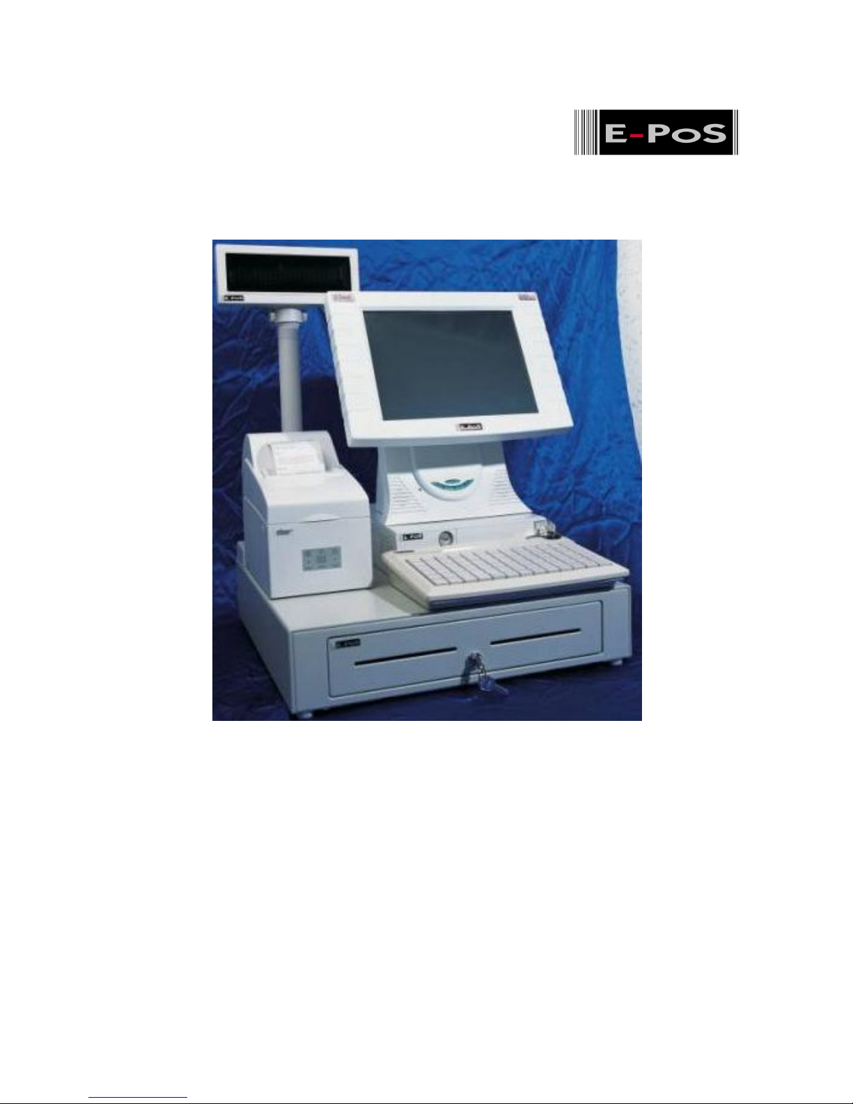
1. E-PoS Magnum System -Power Cord, Driver Bank CD, Keys.
2. 12” LCD Color Monitor –Manual, Power Cord, VGA Cable, Stereo Cable.
3. Star SP 542 Printer –Power Cord, Printer Interface Cable, Ribbon
4. ECD 7303 –VFD & Cable, Base Unit, Poles, Adapter, Serial
Cable.
5. ECH 460A Cash Drawer –Keys (2Nos).
6. Programmable Keyboard
78 Keys. –Floppy Disk, Keys (3Nos), Numeric Keys, Key Caps,
Expansion Keys, Converter (PS/2).
# General Information
The E-POS MAGNUM is an Intel Celeron / Pentium III (Socket
370) Multimedia ATX motherboard with LCD/VGA controller, Ethernet 100/10, AC97
sound, and IDE flash disk. By integrating single chip, SiS630ST, the
E-POS MAGNUM provides a high performance / low cost desktop solution.
Highly integrated, the E-POS Magnum can adapt Intel. Celeron (66MHz) and
Pentium III (100/133MHz) CPU. Onboard features include four serial ports, two
multi–mode Parallel ports, a floppy drive controller and a PS / 2 keyboard PS / 2
mouse interface. The built-in high speed PCI IDE controller supports both PIO and ATA
100 mode. Up to four IDE devices can be connected, including large hard disks,
CD-ROM drives and other IDE devices.
The full PC functionality coupled with its multi-I/Os stand ready to accommodate
a wide range of PC peripherals. Compact in size and with its highly integrated
multimedia and networking functions, the E-POS Magnum is the most powerful PC
engine to build any small footprint all-in-one PC system for integration into any
space-constricted embedded applications. Fully configurable and with its modular
design, the E-POS Magnum is an ideal platform for any consumer computing
applications where space is a premium.

6
# Specifications
E-POS MAGNUM:
Multimedia I nt el Celeron/Pentium I II FLEX ATX Motherboard wi t h XGA, LCD,
T V- out, Dual display, Ethernet & Audio I nt er face
CPU:
I ntel Socket 370
I ntel Tualatin FCPGA up t o 1 . 2 6 GH z
I ntel Pentium III FCPGA 66/100/133 up t o 1 GH z
Celer on FCPGA 6 6 /100 up to 1 . 3 GH z
Main Chipset: SiS630ST
Super I/O:
Winbond W83697HF & W8 3627F
• W83697HF: UART1, UART2, Parallel Port 1 FDC, Game/MIDI , I R/CI R,
Har dwar e Moni t or
• W83627F: UART3, Parallel Port 2, UART4 (Pin 1/9 power suppor t )
System BIOS: Award PnP Flas h BI OS
System Memory:
2 x 168 pin DI MM s ock et s suppor t i ng S DRAM up t o 1 GB
L2 Cache: CPU built- in
Standard I/O
• S er ial ports x 4: COM 1 ~ 4, COM 2 & 4 with + 5V/12 power output on pin
# 9
• Parallel port x 2: Suppor t S PP/EPP/ECP;
• AT A 100/66 IDE x 2: suppor t s up t o 4 IDE devices
• FDD x 1: suppor t s up t o 2 floppy disk drives
• PS /2 Keyboard I nt er face x 1
• I nter nal Keyboard I nt er face x 1
• PS /2 Mouse I nt er face x 1
• US B Interface x 4: 2 internal and 2 external

7
• GAME/MI DI port
Ethernet
• 100/10 Base-T Ethernet with RJ- 45
Display
• LCD controller
• I ntegr ated 2 D/3D graphics engine, 4X AGP
• S har e s ys tem memory architecture abl e to ut i lize t he di s pl ay memory size
up to 64MB
• Maximum res olution for video chi ps et : 640x480, 800x600, 1024x768,
1280x1024, 1600x1200, and 1920x1200, true- color
• S uppor ti ng L CD/VGA dual dis play mode
(Under Windows 98 and Wi ndows ME)
2nd Display Board (optional):SiS301
• S uppor ti ng VGA/L CD (panel link) or VGA/TV or VGA/VGA,1 among 3
• LCD: Digital flat panel, suppor t i ng panel link
• Video: S- Video or RCA
• When the 2 nd dis play is installed, the pr imar y display will be changed t o
VGA onl y
Audio Function
• Full duplex and i ndependent sample r at e conver ter for audio r ecor di ng &
playback
• S uppor t s Microsoft DirectS ound
• 3D positional audio effects
• Hi- per for mance, mixed- s ignal, stereo
• MI C- I n, Speaker- Out, Line- I n
• Pin header for CD- audio i n
Hardware Monitor
• Monitor ing pr ocessor & s ys tem
• Monitor ing 5 VS B , VBAT, 1.5V, 3.3V, + 5V, + 12V, - 12 V, and pr ocessor
voltages
• Monitor ing pr ocessor, chassis fan speeds
• Contr olling pr ocessor and chas s i s fan speed and failure al ar m
• Automatic f an on/off control
• Read back capability that displays temperature, voltage and fan speed
8
• S uppor ti ng I ntel processor thermal diode output (real processor
temper atur e)
• Watchdog t i mer (64 level time i nt er vals )
• Digital I N x 2 Digital OUT x 2
Expansion Bus: PCI * 1 & AMR* 1
Power: AT X power
Form Factor: FLEX ATX
Dimension: 229* 191 mm (9“x7.5”)
*Specifications are subject to change without notice.
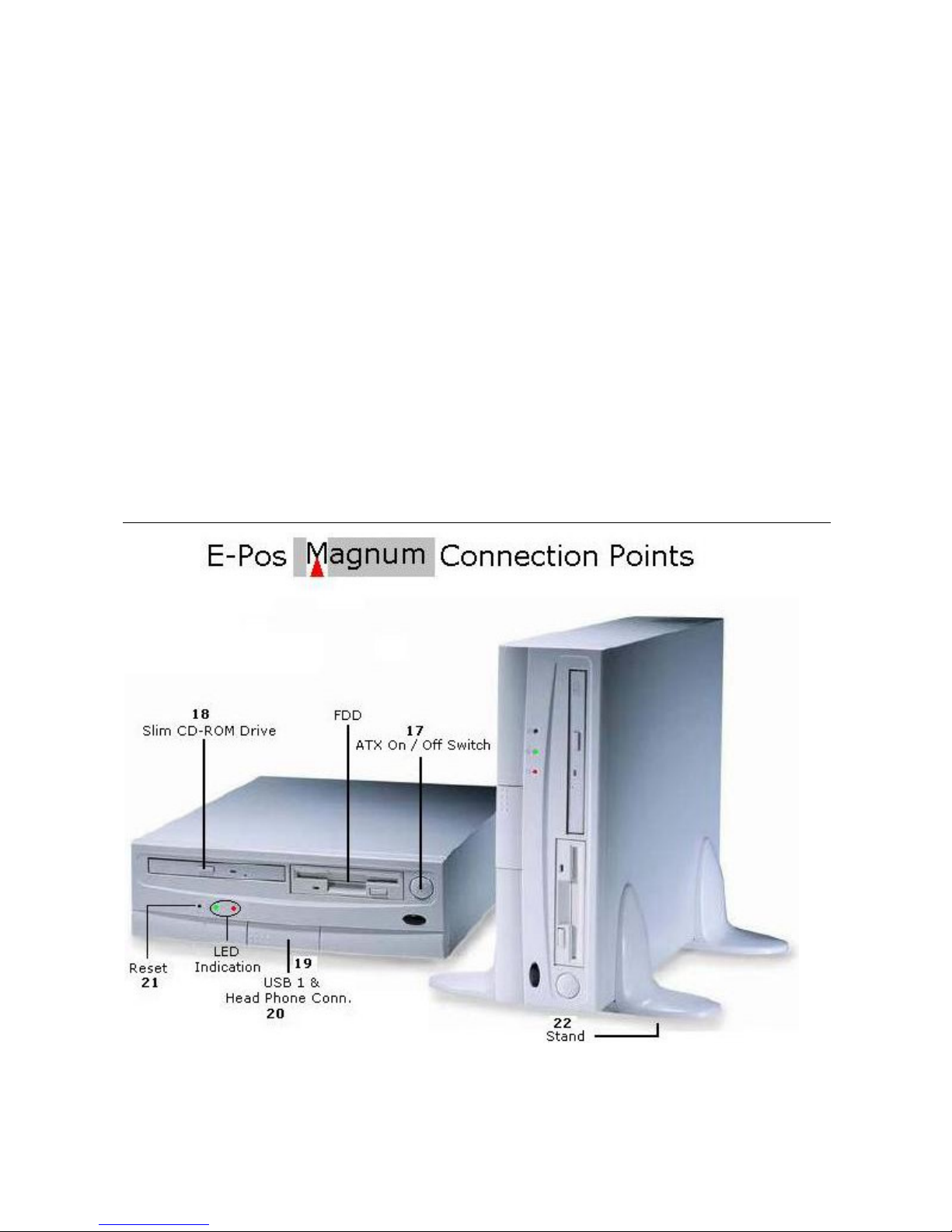
# Connection Diagram
9

10
# Jumper Settings
T he E - POS Magnum is configured t o match the needs of specific
application by proper jumper settings. The onboar d
Connectors link the E - POS Magnum to ex ter nal devices such as
a har d di s k , a fl oppy disk or a pr i nt er. The fol l owi ng fi gur e hel ps you to
locate all jumpers and connectors .

11
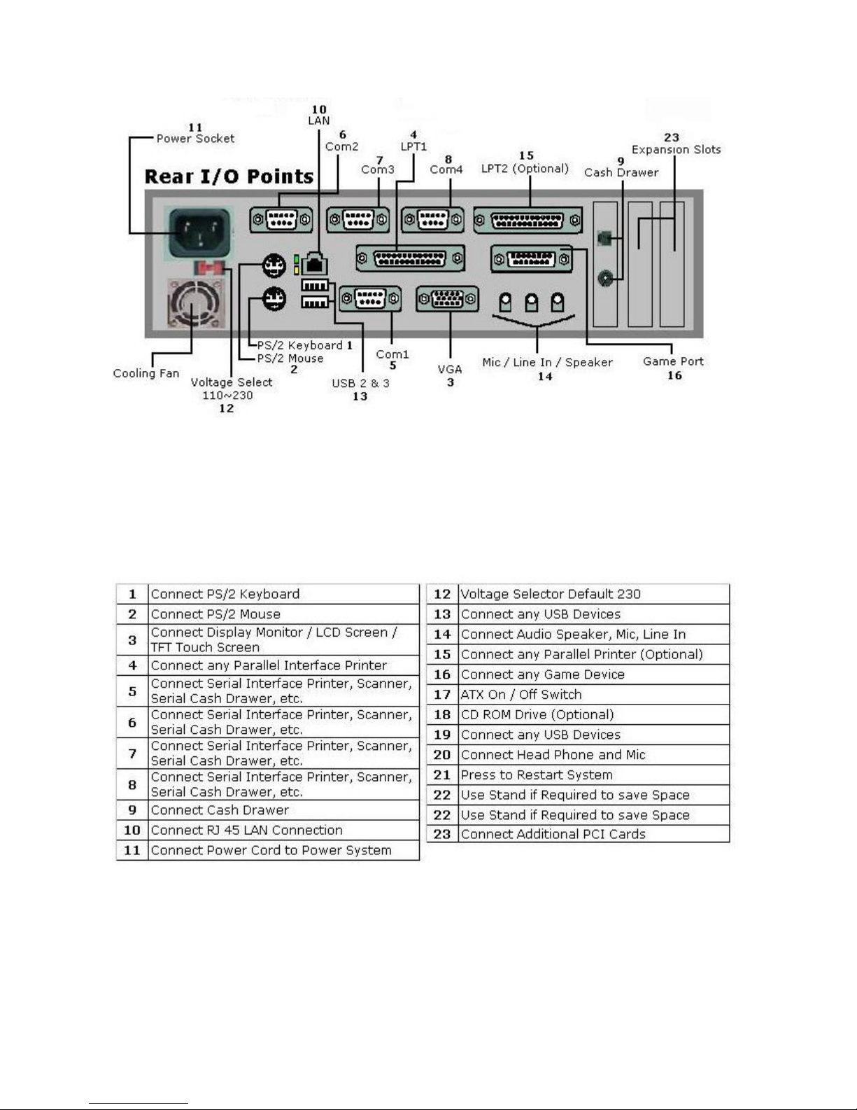
T he fol l owi ng fi gur e s hows the l ocat i on of the r ear side
Connectors .

12
T he t abl e bel ow lis ts the funct i on of each jumper. The
Coming s ecti ons indicate how to s et jumpers to confi gur e t he E - POS
Magnum. They als o i ndi cate t he E - POS Magnum’s default configuration and
options for each j umper.
JP4: COM2/COM4 Pin9 Power selection
JP5: Clear CMOS
13
# Hardware Installation
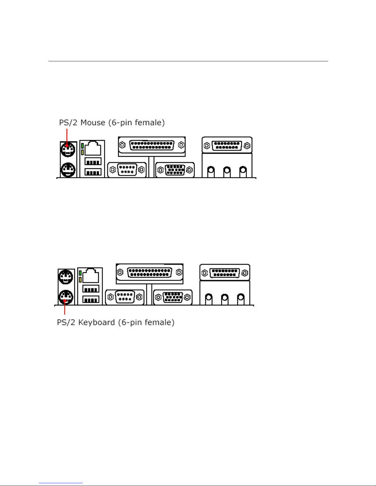
PS/2 Mouse Connector
T he PS /2 Mouse a 6 - pin female connector.
PS/2 Keyboard Connector
T he connector is for a s t andar d k eyboar d us i ng a PS / 2 Plug. For standard
AT keyboard pl ug, a AT - PS /2 adapter is needed for the connection.
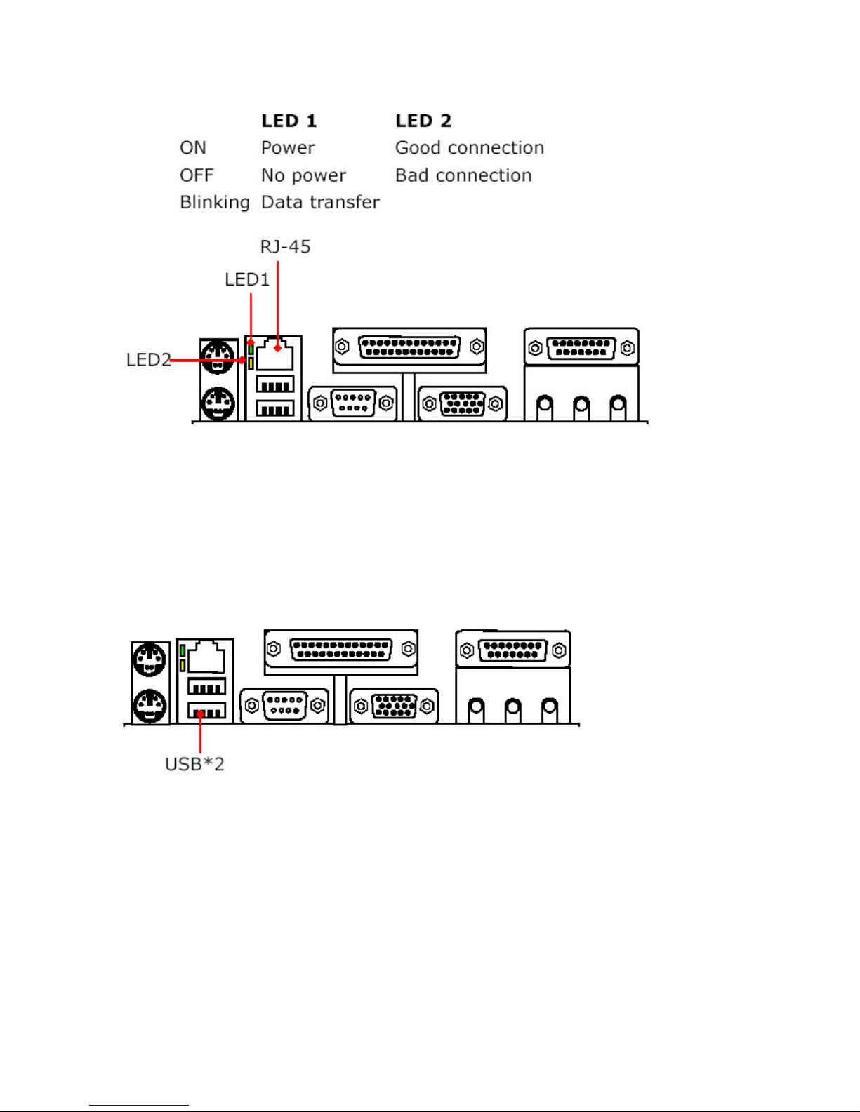
Ethernet Connector
T he E - Pos Magnum features with a 3 2 - bit PCI - bus Ethernet
I nter face wi t h RJ- 45 connector. This high performance L AN interface i s
s uppor t ed by all major network operating s ys t ems .
T her e ar e two L E D’s indicating the net wor k i ng s t atus .
14
USB Connectors
T he E - Pos Magnum provides two ex t er nal USB (Universal Serial Bus) ports
to connect to U S B devices. It also pr ovi des two i nt er nal USB interface for
mor e U S B device connection. The t wo i nter nal USB interfaces have t o be
accessed t hr ou gh the 8 - pin CN4.
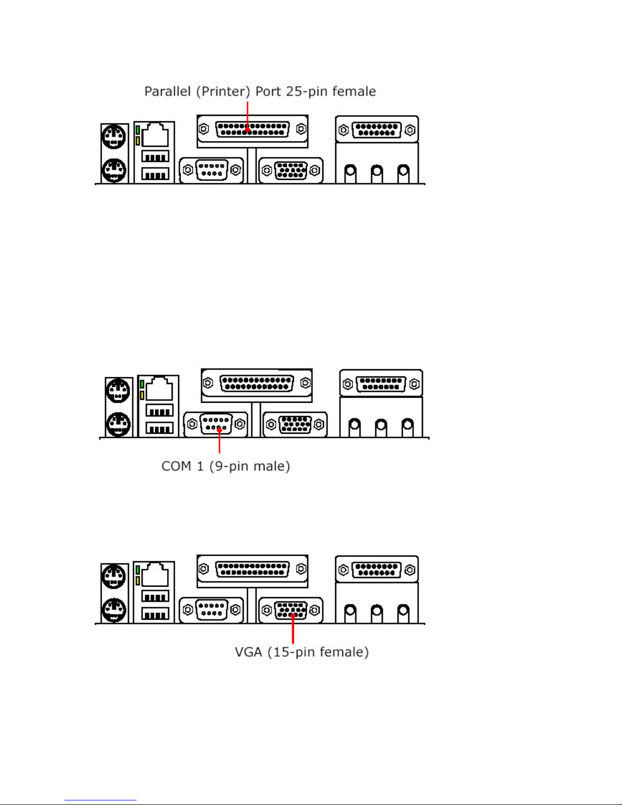
Parallel Port Connector
T he E - Pos Magnum provides a 25- pin female ex t er nal parallel connector
(LPT 1). It also pr ovi des a 26- pin internal parallel header connector (LPT2).
If the 2 nd parallel port is needed, a 2 6 - pin to 25- DUB parallel cable i s
pr ovided t o connect LPT 2 for parallel device
connection.
15
Serial Port Connector
T he E -Pos Magnum pr ovides four onboard s er i al ports for connection to any serial devices
s uch as card r eader, touch screen and fax modem. COM 1 is a 9 - pin male ex t er nal serial
connector (COM1). COM 2 , COM 3 and COM 4 are 1 0 - pin internal serial header connectors .
10-pin to 9 - DU B serial cables are pr ovided t o connect
I nter nal COM por t s for more s er i al device connection. COM 4 is equipped
with + 5V/12V power output on pin 1 and pi n 9. For COM 4 power setting,
CRT VGA Connector
T his connector is for output to a VGA compatible devi ce.
Game/MIDI Connector

16
T he game/MI DI is a gol d 1 5 - pin connector. The us er can connect game
j oys ticks or game pads to thi s connector for playing computer games.
Audio Connectors
T he E - Pos Magnum’s audio connectors include Speaker-out, Line in and
MIC-in. The s peak er - out is to out put the audi o to ex ter nal devices such as
s peaker s or earphones. The l i ne- in is used t o i nput audio fr om an external
audio devi ce s uch as a CD player, tape r ecor der or a r adi o. The
micr ophone- in is used t o connect to an external microphone to r ecor d
s ound or voice.
ATA 100/66 IDE Connectors
T he E - Pos Magnum provides 2 40- pin I DE header connector s able t o
s uppor t up to 4 I DE devices. It also pr ovi des a AT A 100/66 I DE hard di s k
r ibbon cable and a 40- pin to 40 pin I DE cable for IDE device connection. If
two I DE drives are us ed, the s econd dr i ve mus t be confi gur ed t o S l ave
Mode by setting its jumpers
Accor dingly. You can configure t wo har d di s k drives to be bot h Masters with
two I DE cables, one for primary I DE and the other
for secondary I DE connector.

17
FDD Connector
T he E - Pos Magnum provides a 34- pin header type connector (FDC), able t o
attach two fl oppy drives. A 34-34- r ibbon cable i s needed t o connect the
onboar d F DD to fl oppy disk drives.
# General FAQ’s
Q1.
There are no dipswitch settings for the LCD customer display
you provided. We cannot control the display.
Q2.
What is the maximum current of a COM port?
Q3.
Windows cannot detect CD-ROM sometimes.
Q4.
What are VGA, SVGA, and XGA?
Q5.
How to solve the conflict between PS/2 Mouse and LAN?
Q6.
How to set CPU-SDRAM Frequency under Bios for E-Pos
Magnum (Super Market Model)
Q7.
What command do I use to open the Cash Drawer through
the Printer using, a). Star Emulation and b). Epson (esc/pos)
Emulation?
Q8.
What use the Purple Ribbon?
Q9.
Why does my Receipt Printer print Question Marks at the
Beginning of a Print Run?
Q1.
There are no dipswitch settings for the LCD customer display
you provided. We cannot control the display.
A1.
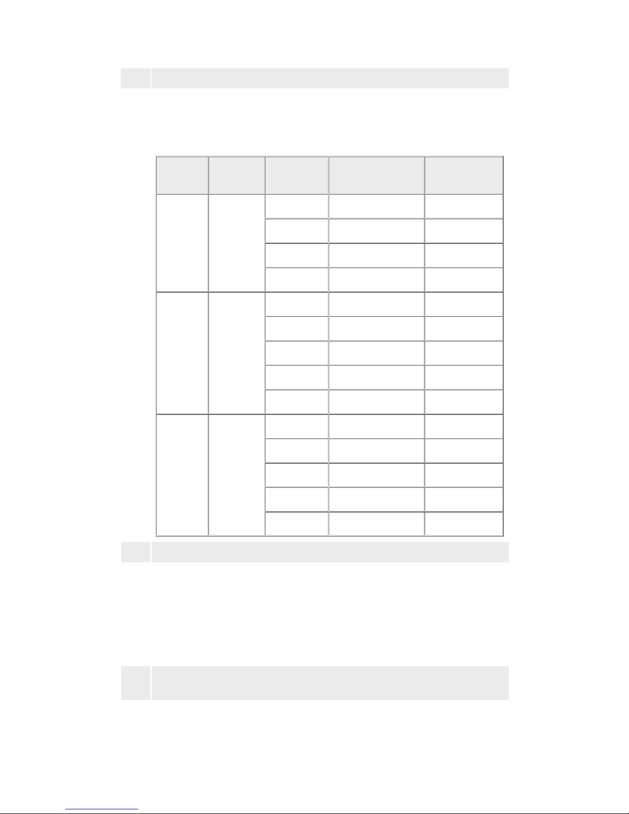
Please refer to the following table for dipswitch settings.
a. Command type selection
SW1
SW2
SW3
Command type
ON
ON
ON
POS7300
OFF
ON
ON
ESC/POS
ON
OFF
ON
ADM 787
OFF
OFF
ON
DSP800
ON
ON
OFF
AEDEX
OFF
ON
OFF
UTC/P

18
ON
OFF
OFF
UTC/S
OFF
OFF
OFF
CD5220
b. International character set
SW4
SW5
SW6
SW7
Character set
Code table ( 80H-FFH )
ON
ON
ON
ON
U.S.A.
PC-437 (USA, Standard
Europe)
OFF
ON
ON
ON
FRANCE
PC-850 (multilingual)
ON
OFF
ON
ON
GERMANY
PC-850 (multilingual)
OFF
OFF
ON
ON
U.K.
PC-850 (multilingual)
ON
ON
OFF
ON
DENMARK I
PC-850 (multilingual)
OFF
ON
OFF
ON
SWEDEN
PC-850 (multilingual)
ON
OFF
OFF
ON
ITALY
PC-850 (multilingual)
OFF
OFF
OFF
ON
SPAIN
PC-850 (multilingual)
ON
ON
ON
OFF
JAPAN
Katakana
OFF
ON
ON
OFF
NORWAY
PC-850 (multilingual)
ON
OFF
ON
OFF
DENMARK II
PC-850 (multilingual)
OFF
OFF
ON
OFF
SLAVONIC
ON
ON
OFF
OFF
RUSSIA
OFF
ON
OFF
OFF
U.S.A.
PC860 (Portuguese)
ON
OFF
OFF
OFF
Not used
OFF
OFF
OFF
OFF
User define pattern from EEPROM
c. Baud rate selection
SW8
SW9
Baud rate (bps)
ON
ON
4800
OFF
ON
9600
ON
OFF
19200
OFF
OFF
38400
d. Parity check selection
SW10
Parity check
ON
None-parity
OFF
Even-parity
e. Demo mode selection
SW11
Show demo string
ON
Enable
OFF
Disable
f. DIP switch setting selection
SW12
DIP1~DIP11 Switch
ON
Power on select hardware DIP SW setting
OFF
Power on select software EEPROM setting

19
g. Software status setting
When system POWER ON, there is no need to turn off to modify
Command Type, Baud Rate, Parity, Demo Mode and International
Character. To re-set DIP Switch to various Command Type under
the following list of Command to modify the setting. The setup value
will store in the EEPROM. When DIP Switch is OFF. Next time the
system POWER ON previous setup value will be the default value
and no need to modify. The followings are examples for software
status setting
Step1 Initial port:
C:\mode com1 (~4): 9600, N, 8,
1
Result: Status for device com1:
---------------------------------
Baud: 9600
Parity: None
Data Bits: 8
Stop Bits: 1
Time Out: Off
XON/XOFF: OFF
CTS handshaking: OFF
.
.
RTS circuit: ON
Step 2 Command Control
C:\debug
-0 3f8 1B ----¡Ö ESC code
-0 3f8 71 ----¡Ö q
-0 3f8 65 ----¡Ö a
-0 3f8 41 ----¡Ö ASCII41="A"
-0 3f8 42 ----¡Ö ASCII42="B"
-0 3f8 43 ----¡Ö ASCII43="C"
-0 3f8 D ----¡Ö End
code="Enter"
output
----¡Öshown in the display
"ABC"
Q2.
What is the maximum current of a COM port?
A2.
0.5 A.
Q3.
Windows cannot detect CD-ROM sometimes.
A3.
This can occur if the computer is installed with a dual-channel
integrated device electronics (IDE) controller. Please follow these
steps:
1.
Click Start, point to Settings, click Control Panel, and then
double-click System.
2.
Click the Device Manager tab.
3.
Click the Hard Disk Controllers branch to expand it, click your
IDE controller and Properties.
4.
Click the Settings tab.
5.
In the Dual IDE Channel Settings box, click Both IDE Channels
Enabled, and click OK.
6.
Click OK, and then restart your computer.
7.
Please visit Microsoft website as
http://support.microsoft.com/default.aspx for further information.
20
Q4.
What are VGA, SVGA, and XGA?
A4.
These are computer resolution standards defined by Video
Electronic Standard Association (VESA). It is an industry standard
for resolutions of personal computers. VGA is 640 x 480, SVGA is
800 x 600, and XGA is 1024 x 768
Standard
Resolution
Refresh
Rate
Horizontal
Frequency
Pixel
Frequency
60Hz
31.5KHz
25.175MHz
72Hz
37.9KHz
31.500MHz
75Hz
37.5KHz
31.500MHz
VGA
640 x 480
85Hz
43.3KHz
36.000MHz
56Hz
35.1KHz
36.000MHz
60Hz
37.9KHz
40.000MHz
72Hz
48.1KHz
50.000MHz
75Hz
46.9KHz
49.500MHz
SVGA
800 x 600
85Hz
53.7KHz
56.250MHz
43Hz
35.5KHz
44.900MHz
60Hz
48.4KHz
65.500MHz
70Hz
56.5KHz
75.000MHz
75Hz
60.0KHz
78.750MHz
XGA
1024 x
768
85Hz
68.7KHz
94.500MHz
Q5.
How to solve the conflict between PS/2 Mouse and LAN?
A5.
Please follow these steps:
1. If there is an IRQ12 conflict between LAN and PS/2 Mouse, the
latter will always occupy IRQ12 because of BIOS priority.
2. To solve the problem, you need a reserve IRQ for LAN.
3. Adjust the BIOS option (IDE, comX, etc. Disable) to get the extra
IRQ.
4. Test until every device works property.
Q6.
How to set CPU-SDRAM Frequency under Bios for E-Pos Magnum
(Super Market Model)
A6.
If any changes or Bios Defaults are set, then the System will run on
a 100 MHz Frequency for CPU and SDRAM, to ensure Correct CPU
and SDRAM Type & Speed, follow these steps,
Table of contents
Popular Cash Register manuals by other brands

Logic Controls
Logic Controls SB9100 Series user manual

Olivetti
Olivetti NETTUN@3000 int'l user guide

Sharp
Sharp XE-A203 - Cash Register Thermal Printing Graphic Logo... quick start guide

Samsung
Samsung ER-5100 Programming & operating manual

POSIFLEX
POSIFLEX CR-2200 Series user manual

Sam4s
Sam4s ER-350 Service manual


