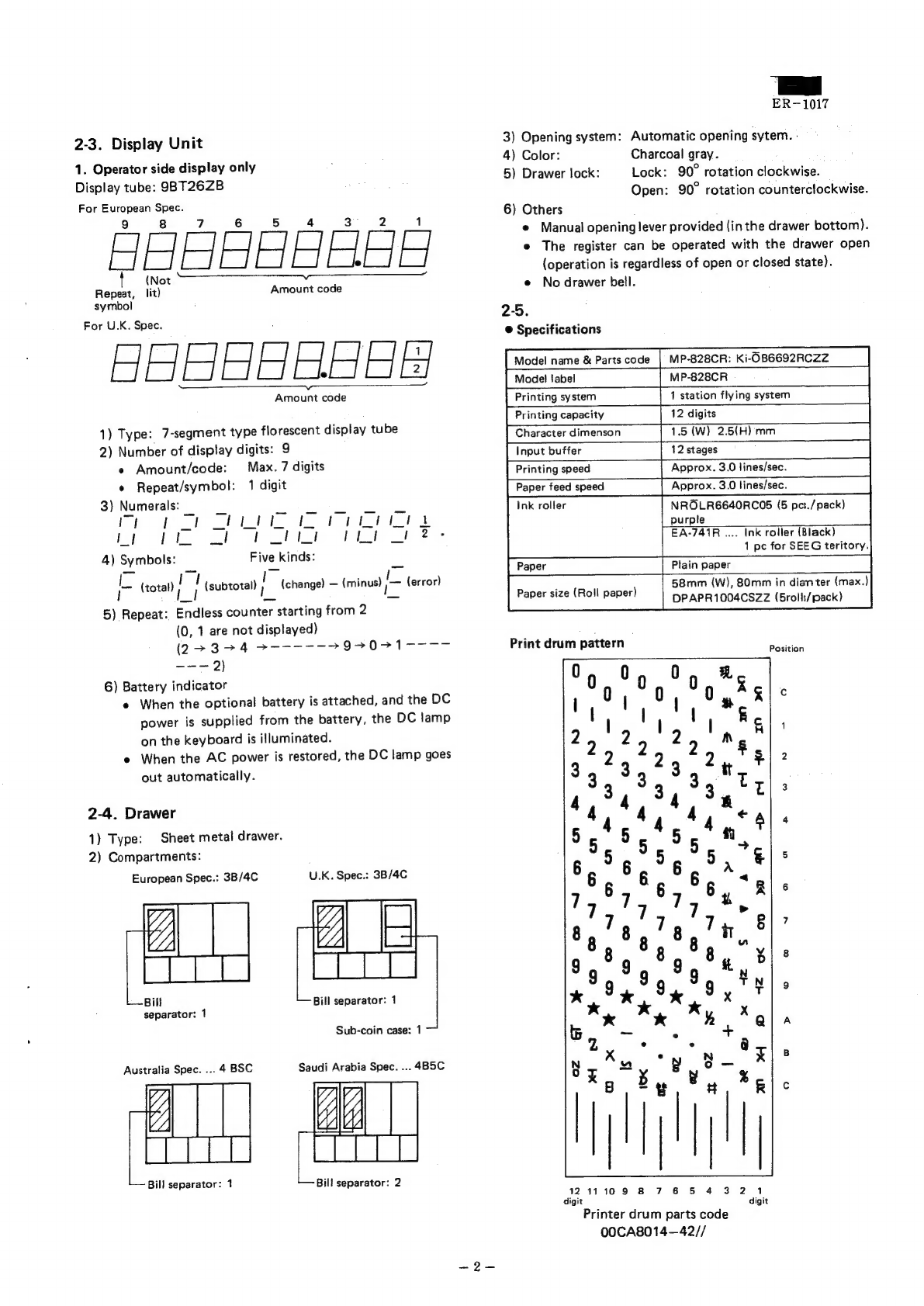
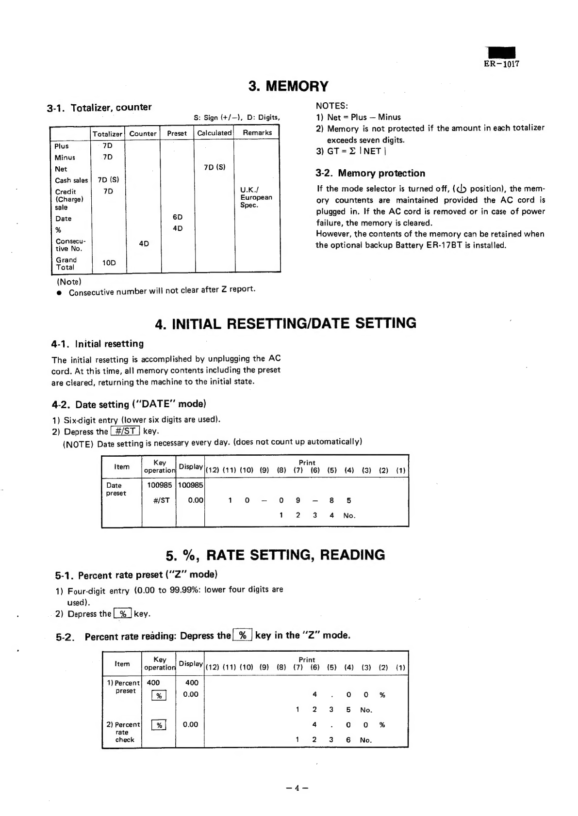
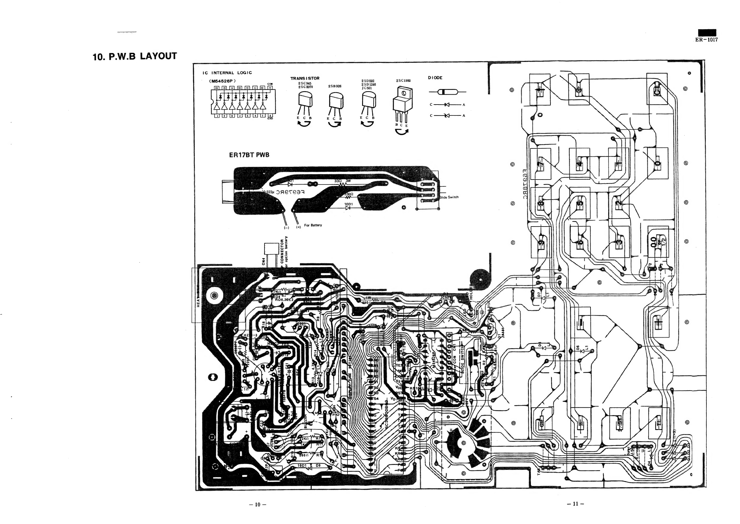
Sharp ER-1017 User manual
Other Sharp Cash Register manuals

Sharp
Sharp XE-A147 Quick manual

Sharp
Sharp ER-2386S User manual

Sharp
Sharp UP-700 Service manual

Sharp
Sharp XE-A137 User manual

Sharp
Sharp XE-A106 User manual

Sharp
Sharp ER-1910 User manual

Sharp
Sharp XE-A506 User manual

Sharp
Sharp XE-A505 - Cash Register, Thermal Printing User manual

Sharp
Sharp XE-A101 User manual

Sharp
Sharp XE-A403 User manual

Sharp
Sharp UP-820N User manual

Sharp
Sharp ER-A320 User manual

Sharp
Sharp XE-A101 User manual

Sharp
Sharp XEA102 - Cash Register User manual

Sharp
Sharp ER-87MA User manual

Sharp
Sharp XE-A402 User manual

Sharp
Sharp XE-A212 User manual

Sharp
Sharp XE-A307 User manual

Sharp
Sharp ER-A247 User manual

Sharp
Sharp ER-A430 Owner's manual