EPOX BXA-M User manual

TRADEMARK
All products and company names are trademarks or
registered trademarks of their respective holders.
These specifications are subject to change without
notice.
Manual Revision 1.4
June 15, 1998
BXA-M
A PentiumA Pentium
A PentiumA Pentium
A Pentium®®
®®
®II or DeschutesII or Deschutes
II or DeschutesII or Deschutes
II or Deschutes
Slot1 Processor based AGPSlot1 Processor based AGP
Slot1 Processor based AGP
motherboard (100/66MHz)

FeaturesBXA-M
Page 1
FEATURES
BXA-M Features:
•BXA-M is based on the Pentium®II or Deschutes Processor operating
at 233 ~ 333MHz (66MHz) or 300 ~ 450MHz (100MHz) on Slot 1. The
board is configured by an Easy-Setting-Single-Jumper (E.S.S.J.) to match
your CPU clock speed.
•Designed with VIA APOLLO PRO 692/596 AGPset.
•Supports up to 768 Mega of DRAM (minimum of 16 MB) on board, You can
use 168-pin DIMM x 3. It will automatically detect Extended Data Output
(EDO) DRAM at 66MHz only or Synchronous DRAM memory (SDRAM)
at 66MHz or 100MHz (please see Section 3-2).
•BXA-M will support Error Checking and Correcting (ECC) when using
paritys DRAM memory modules. This will detect multiple bit errors and
correct 1-bit memory errors.
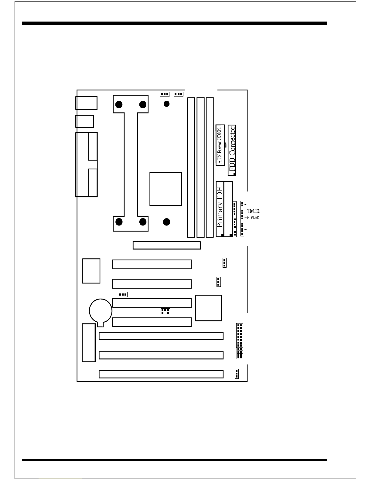
•Supports (3) 16 bit ISA slots, (4) 32 bit PCI slots, (1) AGP slot and provides
(2) independent high performance PCI IDE interfaces capable of supporting
PIO Mode 3/4 and Ultra DMA 33 devices. The BXA-M supports (4)
PCI Bus Master slots and a jumperless PCI INT# control scheme which
reduces configuration confusion when plugging in PCI card(s).
•Supports ATAPI (e.g. CD-ROM) devices on both Primary and Secondary IDE
interfaces.
•Designed with Winbond W83977TF Multi I/O: (1) floppy port, (1) parallel port
(EPP, ECP), and (2) serial ports (16550 Fast UART).
Note: Japanese “Floppy 3 mode” is also supported
•Includes a PS/2 mouse connector.
•Allows use of a PS/2 keyboard.
•Features Award Plug & Play BIOS. With Flash Memory you can always
upgrade to the current BIOS as they are released. (http://www.2themax.com
please visit our Technical Support section for the latest updates)

FeaturesBXA-M
Page 2
•BXA-M utilizes a Lithium battery which provides environmental protec-
tion and longer battery life.
•Supports the Universal Serial Bus (USB) connector. The onboard PIIX4E chip
provides the means for connecting PC peripherals such as; keyboards,
joysticks, telephones, and modems.
•Built-in ATX 20-pin power supply connector.
•Software power-down when using Windows®95.
•Supports ring-in feature (remote power-on through external modem,
allows system to be turned on remotely.
•Resume by Alarm - Allows your system to turn on at a preselected time.
•Power Loss Recovery - In the event of a power outage your system will
automatically turn itself back on without user intervention.
•Supports CPU Hardware sleep and SMM (System Management Mode).
•Supports Desktop Management Interface (DMI) facilitating the management
of desktop computers, hardware and software components and peripherals,
whether they are stand-alone systems or linked into networks. (optional)
•Supports Hot key, Any key or password Keyboard power ON function
(KBPO).
•Supports USDM software to offer motherboard various status on Windows®
95/98, or Windows®NT 4.0/5.0.
•Supports the CPU, PWR and Chassis fan Auto stop in sleep mode.
•Supports the System Power LED (PANEL) blinks in the sleep mode.
•Built-in WOL (Wake On LAN)Connector.
• Built-in SB-LINK Header for Creative Blaster®AWE64D PCI Bus Sound
Card.

InstallationBXA-M
Page 3
PCISlot #4
AGPSlot
CPUCartridgeSLOT1
PCISlot #3
PCISlot #2
PCISlot #1
ISA Slot #1
ISA Slot #2
ISA Slot #3
DIMM 2
DIMM 1
DIMM 3
Battery
SPKKEYLOCK
VIA
692
AGPset
VIA
596
PCIset
Winbond
83977
I/Oset
Flash Memory
for BIOS
COM 1
USB
COM 2
Parallel Port
USB1
(Top)
Mouse
(Top)
USB0
(Bottom)
PS/2Keyboard
(Bottom)
JP1
ChassisFAN
J5
PWRFAN
Bank0
Bank1
Bank2
IDE2FDD1
IDE1
SecondaryIDE
POWER_ON/OFF
RESET
J2
1
J3
IRCONN.
200MHz
266MHz
300MHz
300MHz
233MHz
JP3
JP8
JP10
JP7
JP9
333MHz
360MHz
400MHz
450MHz
500MHz
550MHz
350MHz
(66MHz)(100MHz)
CPUFAN
J5J5
J4
JP13
1
1
ESSJ
J6
J8:SB-LINK15
J7:WOL
Figure 1
BXA-M Detailed Layout

InstallationBXA-M
Page 4
Easy Installation Procedure
The following must be completed before powering on your new system:
Configure Jumpers to match your hardware
Install memory chips
Device Connectors
Configure Jumpers
2theMax designs all motherboards with the fewest jumpers to make your install fast
and easy.
The following will describe all of the jumpers that you are required to set before
moving on to step 2.
Note: The jumpers as depicted as shown (Figure 1) in their correct physi-
cal orientation.
JP13 Keyboard Power-ON function (refer the
s
JP13 = 1-2 - Enabled
= 2-3 - Disabled(Default)
1
3
J7 WOL (Wake On Lan) Connector
Reserved for NIC (Network Interface Ca
r
Wake the System.
JP1 = 1-2 - Run Mode (Default)
= 2-3 - Clear CMOS (momenta
r
JP1 CMOS Clear
1
3
J8 SB-LINK Header
Reserved for Creative SB-LINK (Soun
d
LINK ) with the Sound Blaster AWE64
D
Sound Card to Compatible DOS games a
Multimedia applications.
TM
TM

InstallationBXA-M
Page 5
*:RSD(Reserved)
**
Note: Based on the implementation of Intel 440BX PCIset, BXA-M is able
to provides two host bus frequencies -- either 66 or 100MHz for Slot1 processor
andmemoryoperating. Automatically, thedefaultisat66MHzoncePentium®II
processor to be mounted onto this motherboard. In case of Deschutes processor, it is
self-adjustedto100MHzwithoutanymanualmodificationrequired. However,no
matterwhatkindofSlot1processoryou installed,itshouldcomewithrightmemory
modulesfornormalandstable operation. For example,ifyouinstall a Deschutes
processor, you should use the SDRAM module with 100MHz based(or above) to
match the CPU speed. Furthermore, one thing you may need to bear in mind,
before the CPU installation, it is anyway our advice to use JP3 and set up right
speed of Slot1 processor at any time. You may feel like to know about AGP
interface,whichalwaysrunsunder66MHzno matter what frequencyofprocessor
youinstalled.
JP100 = 1-2 - AUTO (Default)
= 2-3 - PC100 Only
JP100 BUS Clock
1
3

InstallationBXA-M
Page 6
System Memory Configuration
Memory Layout
The BXA-M supports (3) 168-pin DIMMs (Dual In-line Memory Module).
The DIMMs can be either EDO (Extended Data Out) or SDRAM (Synchronized
DRAM). The DIMMs may be installed using just one chip.
•We recommend using SDRAM DIMM can not mixing
with EDO DIMM modules.
• The EDO DIMM only support pentium®II Processor at 66MHz, not
support Deschutes Processor at 100MHz.
• We recommend when installed the 100MHz Deschutes Processor
using DIMM SDRAM must be 125MHz (-8ns) bus speed. If used
100MHz (-10ns) SDRAM may be critical timing for the
motherboard.
• About the “PC/100 SDRAM spec.” information you may visit Inte’s
home page at:
http//developer.intel.com/design/pcisets/memory/index.htm
• DIMM SDRAM may be 83MHz (-12ns), 100MHz (-10ns) or
125MHz (-8ns) bus speed.
Figure 2 and Table 1 show several possible memory configurations using
DIMM 1 (M1)
DIMM 2 (M2)
DIMM 3 (M3)
Bank 0
Bank 1
Bank 2
Figure 2

InstallationBXA-M
Page 7
Table 1
*SDRAM only supports 8, 16, 32, 64, 128MB DIMM modules. 256MB only
supports Registered Synchronouts DRAM Memory Modules.
* EDO only supports Pentium®II Processor at 66MHz, not supports Deschutes
Processor at 100MHz.
yromeMlatoT 1MMID )0knaB( 2MMID )1knaB( 3MMID )2knaB(
BM867= mumixaM
*MARDS/ODE ,BM23,BM61,BM8 BM652,BM821,BM46 1X
BM215= mumixaM
*MARDS/ODE ,BM23,BM61,BM8 BM652,BM821,BM46 1X
enoN
BM652= mumixaM
*MARDS/ODE ,BM23,BM61,BM8 BM652,BM821,BM46 1X
enoNenoN

InstallationBXA-M
Page 8
Device Connectors
Please install the motherboard into the chassis.
Now that your motherboard is installed you are ready to connect all your connections
(figure 12).
USB 1
(Top)
USB 0
(Bottom)
PS/2 Mouse
(Top)
PS/2 Keyboard
(Bottom)
Parallel Port
(Top)
Com1 Com2
(Bottom Left) (Bottom
Right)
J4: CPU Fan Power
• A plug-in for the CPU Fan Power
J5: Power Supply Fan Monitoring
• A plug-in for the Power supply so that BIOS can monitor the RPM’s
J6: Chassis Fan Power
• A plug-in for the chassis Fan Power
J7: WOL (Wake On Lan) Connector
J8: SB-LINK Connector
• 5-PIN Header for Creative Blaster® AWE64D PCI Sound Card.
PW2: ATX Power Connector
• 20-pin power connector
J2,J3:Chassis Panel Connector
• Keylock, Speaker, Reset, Sleep, Turbo LED and HDD LED
IDE1:Primary IDE Connector
IDE2:Secondary IDE Connector
FDD1:Floppy Controller Connector
Figure 12
12345678901234567890123456789012123456789012345678901234567890121234567890123456789012345
12345678901234567890123456789012123456789012345678901234567890121234567890123456789012345

InstallationBXA-M
Page 9
Power On/Off - This is connected to the power button on the case.
Using the Soft-Off by Pwr-BTTN feature, you can choose either
Instant Off (turns system off immediately), or 4 sec delay (you need to
hold the button down for 4 seconds before the system turns off). When
the system is in 4 sec delay mode, 2theMax has added a special feature to
make the system go into suspend mode when the button is pressed
momentarily.
J2
Device Connectors (continued)
Speaker - Connect to the system's speaker for beeping
1. Speaker 3. GND
2. N/C 4. GND
Reset - Closed to restart system.
Turbo LED indicator - LED ON when higher speed is selected
IDE LED indicator - LED ON when Onboard PCI IDE Hard disks is
activate
KeyLock - Keyboard lock switch & Power LED connector
1. Power LED(+) 4. Keylock
2. N/C 5. GND
3. GND
J3 1
+
+
1
* The power LED lights when the
system is powered on and blinks in
SLEEP MODE (Suspend mode).
IR Connector
1. VCC 4. GND
2. NC 5. IRTX
3. IRRX
Table of contents
Other EPOX Motherboard manuals

EPOX
EPOX AMD Socket et A Processor based AGP (8X)... User manual

EPOX
EPOX LX370Y User manual

EPOX
EPOX P55TV2 User manual

EPOX
EPOX 9npa User manual

EPOX
EPOX EP-7KXA User manual

EPOX
EPOX 60002MC10 User manual

EPOX
EPOX S7-530A User manual

EPOX
EPOX EP-6VBA2 User manual

EPOX
EPOX LX370Y User manual

EPOX
EPOX P55-BT User manual