EPS SK202 Series User manual

SK202User manual1of7
UserManual
SK202 ContactlessGbE
1.Overview
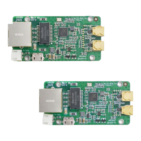
Thisdocumentguidesusershowto usetheSK202A/Bmodules.Thepairof
modulestransmitsGigabitEthernetsignalsatadistanceofseveralcentimetersin a
contactlessway.SK202 opensanewscenefornetworkconnectionapplications.This
moduleintegratesanetworkPHYchipandST60 A2, amillimeterwavewireless
transceiverchip,whichcanbesimply connectedto theexisting Ethernetreplacinga
networkcable. PleasenoteisthatbothSK202modulesmustatthesamespeedmode
asdescribedinsection 3ofthisdocument.
2.Connectionmethod
Figure1.
SchematicdiagramofusingSK202 toconnectIPcamera
SK202only needsto beconnectedto thenetwork and powersupply,butit should
benotedthatthenetwork negotiationrate ofthePCsideandtherouterside are the
same.If the PCside isagigabitnetwork, the rateautomaticallynegotiatedwiththe
SK202Awill be1G.Then the rate ontherouterside mustbe1Gbps,andthe router
willautomatically negotiate the rate withtheSK202Bto be 1Gbps.Thenetworkwill
beconnected,working onGigabit Ethernet.
Assuming that the routerhasa rate of100M, SK202Bwill negotiate a rate of100M
with the router.Atthistime,the rate ofSK202Ais1Gbps, andtheratesofSK202A/B
are inconsistent, andthenetworkwill not work. Please refertosection Controlled
Auto-negotiation’below.
The categoryofthecablesused to connectthe modulesto therestofthe network
mustbecompatible withtherate thatwillbenegotiated. 10/100 or1000Mbps.Please
note thatSK202AandSK202Bmust be used in pairs, andthegolden antenna part
needsto bealignedwitha distance ofabout 3cm.

SK202User manual2of7
Figure2. PhysicalpictureofSK202non-contactconnector
3.ControlledAuto-negotiation
The NetworkPHYchipembeddedin theSK202issetinAuto-negotiationmodeand
isable to support 10/100/1000Mbps. In orderfortheSK202AandSK202Bto
communicate theymustoperateat thesamespeed.The Green LEDon theRJ45
connectorofblinkswhen a 1Gbpscommunication isestablishedbetweenthe local
and the distantPHY.The OrangeLEDsblinkswhen the communication isat10Mbps
ThePHYsontheSK202 workindependently and eachonenegotiates
automatically with thedevice itisconnectedto.Sotwoindependentnegotiationstake
place inparallel.
Asaconsequence,ifthetwodevices,suchasalaptopandacamera, advertise
differentmaximumspeeds,the twoauto-negotiation resultswill differ.
Figure3. Non controlledauto-negotiation mayfail
Forthe SK202communicationtoestablishcorrectlybetweendevices
advertisingdifferentmaximum speedcapabilities, the auto-negotiationof the
fastestdevicehas tobecontrolled.

SK202User manual3of7
Thanksto thecontrolledauto-negotiation onthelaptop,onecanensurethelink
with theSK202will besetupatthesamespeedthantheonebetweenthesecond
SK202andthecamera.
Figure4. Controlledauto-negotiation isrequiredwhenthe2devicesdo notadvertisethesame
maximumspeedcapability
Alternatively,onecanintroduceaswitchoperatingatthesamespeedthantheslowest
device in ordertoensuretheauto-negotiationresultwillbethesameonboth sides.
Figure5. Auto-negotiation result controlledusing aswitch.
4.Performance evaluationmethod
If you need toevaluatethe impact ofSK202onnetworktransmission,itis
recommendedtouse a third-partytoolIPERF3. Only need two networkcable and two

SK202User manual4of7
PCsto complete the test.Youcan download fromthe addressasbelow:
https://iperf.fr/iperf-download.php
Iperf3 testmethod:
Figure6. Iperf3testSchematicdiagramwithSK202
Referto the figure6toconnect to the network.The network adaptersoftwo PCs
need thesamespeed,such asGigabitEthernetcontroller.IPaddress ofPC-Aisset to
192.168.10.2,IPaddressofPC-B issetto192.168.10.3.Please useatleastCat5e-type
cable fortesting
PC-Aasa server,runcommand:
iperf3--server
PC-B asclient, run command:
iperf3--udp --bandwidth1G--client
192.168.10.2--time 100--len63k
IPERF3 will test100secondsthrough UDPprotocolwith 1Gbandwidth, and
therewill be BERandjitterresult outputastheblow picture.
At serverside:
At client side:
If you care about the output ofiperf3 test, acomparison test isnecessary.You can
change the SK202 modulesto aRJ45connectorto directlyconnect twoPCs,and use
the samecommandforcomparison test.

SK202User manual5of7
Figure7. Iperf3testSchematicdiagramwithRJ45 cable
5.Environmentconstraints
FortheRFwavesto propagatecorrectlyfromonemoduleto theother,caremust
betakennotto introduceanymetallicobstaclein aKeepOutArea(KOA),in green
onthefiguresbelow.ThisKOAisaparallelepipedof22mmwidthand9mmheight.
The length being the distance betweenthe antennae, usually30 mm.
Moreover,aSafeAreahasbeendefined,inorangeonthefiguresbelow.The
elementspresent inthisarea mayhaveanimpactonthemillimeterwaves
propagation.
ThisSafeArea isaparallelepipedof60mm width and height. Thelength being
the distance between theantennae, usually 20mm.
Incaseanelectroniccomponent,ametalpart,afastener,ascrew,somemetal
paintoranysortofreflectivesurface residesin thisvolume, itsimpactmustbe
analyzed.
Figure 8. KeepOut Area (Green)andSafe Area (Orange)
In case a metallic casingistobe usedaround themodules, itismandatoryto
insert anopeningforthe millimeterwavesto propagate.Thisopeningmay be filled

SK202User manual6of7
withABSor othermicrowaveinsensitivematerialstomaintainwatertightness. This
openingshouldfollowtheseguidelines:
•Thecasing mustbeplacedataround2.7mm fromthePCBtoensureafree
space of 0.8mmbetweentheHorn antennaebodyandtheABShousing.
•Theopeningshouldbeminimum 22mmlongand9mm wide, centeredon the2
antennae, butitcanbeenlarged.
•Shouldthecasingbeplacedfurtherthan2.7mm fromthePCB,theopening
dimensions will havetobeadjustedtopreventreflections.
Thisis summarizedinthefigurebelow:
Figure 9. Openning inametallichousing
6.Characteristics
Recommendedoperatingconditions andelectrical characteristics
Symbol Description Minimu
m Typical
Maximum
Unit
VIN Powersupply 4.4 12 16 V
CIN Inputcurrent(*) - 50 80 mA
P Total Powerconsumption - 0.6 - W
TAAmbientOperating
Temperature, for SK202AC/BC
0 - 70
TAAmbientOperating
Temperature, for SK202AI/BI -40 - 85
TJMaximumJunction
Temperature - - 125
TSTG StorageTemperature -40 105
AC1 Workingdistanceat50 ,for
SK202AC/BC 1.0 2.0 4.5 cm
AC2 Workingdistanceat0 ,for 1.0 2.0 5.5 cm

SK202User manual7of7
SK202AC/BC
AIWorkingdistanceat85 ,for
SK202AI/BI 1.0 2.0 3.5 cm
Fosc CarrierFrequency 60.3 60.4 60.5 GHz
EIRP OutputEIRP 4 6 8 dBm
*when power supplyis12Vand Ethernet isactive.
7.RFcertification
FCC Part15:
Thisequipmenthasbeentestedandfoundtocomplywiththelimitsfor aClass B
digital device, pursuanttoPart15 of theFCC Rules.
Theselimitsaredesignedtoprovidereasonable protection againstharmful
interferenceinaresidential installation.Thisequipmentgenerate, usesandcanradiate
radiofrequencyenergyand, if notinstalledand usedinaccordancewiththe
instructions, maycauseharmfulinterference toradiocommunications.
However,thereisnoguarantee that interferencewillnotoccurinaparticular
installation.If thisequipmentdoescauseharmfulinterference toradioortelevision
reception,whichcanbedeterminedby turningtheequipmentoffandon,theuseris
encouragedtotrytocorrecttheinterferencebyoneofthefollowing measures:
l Reorientorrelocate thereceiving antenna.
l Increasetheseparationbetweentheequipmentandreceiver.
l Connect theequipmentintoanoutlet on acircuit differentfrom that towhichthe
receiverisconnected.
l Consult thedealer oranexperiencedradio/TVtechnicianforhelp.
Thisdevice complieswithPart15 of theFCC Rules.Operationissubjecttothe
following twoconditions:
(1) Thisdevice maynotcauseharmfulinterference,and(2)thisdevicemustaccept
anyinterferencereceived,including interferencethatmaycauseundesiredoperation.
FCC Caution:Anychangesor modificationsnotexpresslyapprovedby theparty
responsible forcompliancecouldvoidtheuser'sauthoritytooperate thisequipment.
RFexposurewarning
ThisequipmentcomplieswithFCC radiation exposurelimitsset forthforan
uncontrolledenvironment.
Thisproduct maynotbecollocatedoroperatedinconjunction withany otherantenna
or transmitter
Thisequipmentmustbeinstalledandoperatedinaccordance withprovided
instructionsandtheantenna(s)usedfor thistransmittermustbeinstalledtoprovidea
separationdistanceof at least20cmfrom all personsandmustnotbecollocatedor
operatinginconjunctionwithanyother antennaortransmitter.
Revision History
Date Version Changes
JAN12 2021 1.1 Updateworkingdistance characteristicsand FCCPart
NOV022020 1.0 InitialRelease
Other manuals for SK202 Series
2
This manual suits for next models
2
Table of contents
Other EPS Control Unit manuals
Popular Control Unit manuals by other brands

tams elektronik
tams elektronik KSM-2 manual

NEW ENERGY
NEW ENERGY PV installation instructions

Profi-pumpe
Profi-pumpe PSM01142VK operating instructions

Valve Concepts
Valve Concepts 3000 SERIES Installation, operation and maintenance manual

Glovii
Glovii GW2RC instruction manual

Crux
Crux Sightline RVCGM-80F quick start guide