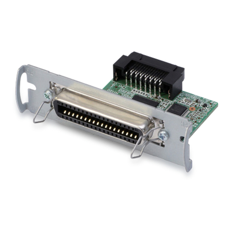
Epson S5U13U00P00C100 User manual

Revision 1.0
S5U13U00P00C100 USB 2.0 Adapter
Board User Manual
Document Number: I00Z-G-018-01
Status: Revision 1.0
Issue Date: 2007/03/20
© SEIKO EPSON CORPORATION 2007. All Rights Reserved.
Information in this document is subject to change without notice. You may download and use this document, but only for your own use in
evaluating Seiko Epson/EPSON products. You may not modify the document. Epson Research and Development, Inc. disclaims any
representation that the contents of this document are accurate or current. The Programs/Technologies described in this document may contain
material protected under U.S. and/or International Patent laws.
EPSON is a registered trademark of Seiko Epson Corporation. All other trademarks are the property of their respective owners.

Page 2 Epson Research and Development
Vancouver Design Center
S5U13U00P00C100 USB 2.0 Adapter Board User Manual
I00Z-G-018-01 Issue Date: 2007/03/20
Revision 1.0

Epson Research and Development Page 3
Vancouver Design Center
S5U13U00P00C100 USB 2.0 Adapter Board User Manual
Issue Date: 2007/03/20 I00Z-G-018-01
Revision 1.0
Table of Contents
1 Introduction . . . . . . . . . . . . . . . . . . . . . . . . . . . . . . . . . . . . . . . . 5
2 Features . . . . . . . . . . . . . . . . . . . . . . . . . . . . . . . . . . . . . . . . . . 6
3 Installation . . . . . . . . . . . . . . . . . . . . . . . . . . . . . . . . . . . . . . . . 7
3.1 USB driver . . . . . . . . . . . . . . . . . . . . . . . . . . . . . . . . 7
4 Technical Description . . . . . . . . . . . . . . . . . . . . . . . . . . . . . . . . . . 8
4.1 Power . . . . . . . . . . . . . . . . . . . . . . . . . . . . . . . . . . 8
4.2 Host Bus Power . . . . . . . . . . . . . . . . . . . . . . . . . . . . . . . 8
4.3 Status Indicators . . . . . . . . . . . . . . . . . . . . . . . . . . . . . . 9
5 Parts List . . . . . . . . . . . . . . . . . . . . . . . . . . . . . . . . . . . . . . . . 10
6 Schematics . . . . . . . . . . . . . . . . . . . . . . . . . . . . . . . . . . . . . . . 14
7 PCB Layout . . . . . . . . . . . . . . . . . . . . . . . . . . . . . . . . . . . . . . . 18
8 Sales and Technical Support . . . . . . . . . . . . . . . . . . . . . . . . . . . . . 20
8.1 Ordering Information . . . . . . . . . . . . . . . . . . . . . . . . . . . 20

Page 4 Epson Research and Development
Vancouver Design Center
S5U13U00P00C100 USB 2.0 Adapter Board User Manual
I00Z-G-018-01 Issue Date: 2007/03/20
Revision 1.0

Epson Research and Development Page 5
Vancouver Design Center
S5U13U00P00C100 USB 2.0 Adapter Board User Manual
Issue Date: 2007/03/20 I00Z-G-018-01
Revision 1.0
1 Introduction
This manual describes the setup and operation of the S5U13U00P00C100 USB2.0 Adapter
Board. This board was designed as an evaluation interface for connecting Epson LCD
Controllers Evaluation Boards to a computer using USB connection.
This user manual is updated as appropriate. Please check the Epson Research and Devel-
opment Website at www.erd.epson.com for the latest revision of this document before
beginning any development.
We appreciate your comments on our documentation. Please contact us via email at
documentati[email protected]n.com.

Page 6 Epson Research and Development
Vancouver Design Center
S5U13U00P00C100 USB 2.0 Adapter Board User Manual
I00Z-G-018-01 Issue Date: 2007/03/20
Revision 1.0
2 Features
The S5U13U00P00C100 USB2.0 Adapter Board includes the following features:
• Header Signals for connecting Epson LCD Controllers Evaluation Boards
• 5V input power (separate power input, not from USB)
• 3.3V power supply available for Epson LCD Controllers Evaluation Boards
• LED power indicator
• Bidirectional voltage translation buffers for the host bus signals, to interface to wide
range of host bus voltages

Epson Research and Development Page 7
Vancouver Design Center
S5U13U00P00C100 USB 2.0 Adapter Board User Manual
Issue Date: 2007/03/20 I00Z-G-018-01
Revision 1.0
3 Installation
S5U13U00P00C100 board should be connected to the Epson LCD Controllers evaluation
board before applying power. To connect the boards, align sockets P1 and P2 on
S5U13U00P00C100 board with headers P1 and P2 on the Epson LCD Controllers evalu-
ation board and connect the two boards.
After the boards are connected, 5V power may be connected to S5U13U00P00C100. Once
the power is applied, the USB cable from the PC may be connected to S5U13U00P00C100
board.
3.1 USB driver
S5U13U00P00C100 USB Adapter board needs the Epson USB driver, S1D13XXXUSB,
installed on the host computer.
The driver may be installed prior to connecting the S5U13U00P00C100 board to the USB
or at the time of the first connection, when the Windows will detect new hardware and will
prompt to install the driver.
Note
If the board does not work after USB cable is connected, remove the USB cable, remove
the power and then connect the power back and reconnect the USB cable.

Page 8 Epson Research and Development
Vancouver Design Center
S5U13U00P00C100 USB 2.0 Adapter Board User Manual
I00Z-G-018-01 Issue Date: 2007/03/20
Revision 1.0
4 Technical Description
4.1 Power
S5U13U00P00C100 does not uses power from the USB. The boards need an external 5V
power supply. The power supply should be able to supply a current up to 2A at 5V.
The external power supply may be connected to PWR1 power jack. This is regular power
jack, with a 2.1mm diameter center pin. The positive of the power supply must be on the
center terminal.
S5U13U00P00C100 has internal voltage regulator to generate all the internal voltages and
also the 3.3V power available for the Epson LCD Controllers evaluation board. The 3.3V
power is available on pin 5 of P2 socket.
4.2 Host Bus Power
S5U13U00P00C100 has voltage translation buffers for the host bus. The voltage of the host
bus may be provided by the Epson LCD Controllers evaluation boards, through pin 11 of
connector P1, or it may be provided by the 3.3V voltage regulator on S5U13U00P00C100.
The host bus voltage is selected with JP1 jumper.
JP1 - Host Bus Voltage
JP1 selects the voltage level of the host bus on connectors P1 and P2.
When the jumper is at position 1-2, the voltage level is HIOVDD provided by the Epson
LCD Controllers evaluation boards (recommended setting).
When the jumper is at position 2-3, the voltage level is +3.3V.

Epson Research and Development Page 9
Vancouver Design Center
S5U13U00P00C100 USB 2.0 Adapter Board User Manual
Issue Date: 2007/03/20 I00Z-G-018-01
Revision 1.0
Figure 4-1: Jumper JP1 Location
4.3 Status Indicators
S5U13U00P00C100 has a green LED “5V PWR” to indicate when 5V power is present.
The board outputs 2 signals on connector P1 to indicate if the board is working and if the
board has completed enumeration on USB.These signals are 3.3 volt, regardless of the host
bus voltage selection.
On pin 9 of connector P1 is output the signal ‘Heartbeat’. When the board is working
correctly, this is a toggling signal with a frequency around 2Hz. If a LED is used as an
indicator, it will be blinking.
On pin 10 of connector P2 is output the signal ‘Enumerated’. This signal goes high when
the S5U13U00P00C100 enumerated successfully on the USB. If a LED is used as an
indicator, it will turn on upon successful enumeration on the USB.

Page 10 Epson Research and Development
Vancouver Design Center
S5U13U00P00C100 USB 2.0 Adapter Board User Manual
I00Z-G-018-01 Issue Date: 2007/03/20
Revision 1.0
5 Parts List
Table 5-1:
Item Quantity Reference Part PCB
Footprint Notes
159
C1,C4,C5,C7,C8,C9,
C10,C11,C12,C13,C28,
C32,C33,C36,C37,C40,
C41,C44,C45,C48,C49,
C52,C53,C56,C57,C60,
C61,C102,C103,C104,
C105,C106,C107,C108,
C109,C110,C111,C157,
C158,C159,C160,C161,
C162,C163,C164,C165,
C166,C172,C173,C174,
C175,C176,C180,C185,
C186,C196,C197,C200,
C205
0.1uF C0402 Yageo America
04022F104Z7B20D
26
C2,C3,C178,C179,C194,
C195 10uF 16V T C3528 Kemet
T494B106K016AS
365
C6,C14,C15,C16,C17,
C18,C19,C20,C29,C30,
C31,C34,C35,C38,C39,
C42,C43,C46,C47,C50,
C51,C54,C55,C58,C59,
C82,C83,C84,C85,C86,
C87,C88,C89,C90,C91,
C92,C93,C94,C95,C96,
C97,C98,C99,C100,
C101,C137,C138,C139,
C140,C141,C142,C143,
C144,C145,C146,C147,
C148,C149,C150,C151,
C152,C153,C154,C155,
C156
0.01uF C0402 Panasonic - ECG
PCC103BQCT
451
C21,C22,C23,C24,C25,
C26,C27,C62,C63,C64,
C65,C66,C67,C68,C69,
C70,C71,C72,C73,C74,
C75,C76,C77,C78,C79,
C80,C81,C117,C118,
C119,C120,C121,C122,
C123,C124,C125,C126,
C127,C128,C129,C130,
C131,C132,C133,C134,
C135,C136,C177,C189,
C193,C201
1nF C0402 Yageo America
04022R102K9B20D
510
C112,C113,C114,C115,
C116,C167,C168,C169,
C170,C171
1uF C0402 Panasonic - ECG
ECJ-0EB0J105M
6 2 C181,C199 4.7uF 10V T C3528 Kemet
T491B475K010AS

Epson Research and Development Page 11
Vancouver Design Center
S5U13U00P00C100 USB 2.0 Adapter Board User Manual
Issue Date: 2007/03/20 I00Z-G-018-01
Revision 1.0
7 2 C182,C198 470uF 6.3V T C7343
Kemet
T494D477M006AS
CAPACITOR TANT 470UF 6.3V SMT
8 4 C183,C184,C187,C188 10uF C0805 Panasonic - ECG
ECJ-CV50J106M
9 2 C190,C202 15nF C0402 Panasonic - ECG
ECJ-0EF1E153Z
10 2 C191,C204 1.5nF C0402 Yageo America
04022R152K9B20D
11 2 C192,C203 47nF C0402 Kemet
C0402C473K4RACTU
12 2 D1,D4 LL4148 MiniMELF Diodes Inc.
LL4148-13
13 2 D2,D5 STPS2L30A SMA STMicroelectronics
STPS2L30A
14 1 D3 5V Power LED0603
Panasonic - SSG
LNJ308G8LRA
LED GREEN SS TYPE LOW CUR SMD
15 1 H1 HEADER 6X2
16 1 JP1 Host IO SIP3 CONN HEADER VERT 3POS .100 TIN or
GENERIC
17 1 J1 USB B
Receptacle USB_B AMP/Tyco
787780-1
18 1 L1 1.6uH ETQP6F Panasonic - ECG
ETQ-P6F1R6SFA
19 1 L2 1.2uH ETQP6F Panasonic - ECG
ETQ-P6F1R2HFA
20 1 PWR1 Power Jack SMT_PJ00
2BSM
CUI Stack Inc.
PJ-002A-SMT
21 2 P1,P2 SOCKET_20x2 HDR2X20 Sullins Electronics
PPWN102AFCN
22 2 Q1,Q2 IRF8910 SOIC-8 International Rectifier
IRF8910
23 4 R1,R2,R107,R117 2.7K R0603
24 1 R3 0 R0603
25 27
R4,R5,R7,R8,R12,R13,
R15,R16,R17,R18,R19,
R20,R21,R22,R80,R81,
R82,R83,R84,R85,R86,
R87,R88,R96,R97,R98,
R99
0 R0402
Table 5-1:
Item Quantity Reference Part PCB
Footprint Notes

Page 12 Epson Research and Development
Vancouver Design Center
S5U13U00P00C100 USB 2.0 Adapter Board User Manual
I00Z-G-018-01 Issue Date: 2007/03/20
Revision 1.0
26 64
R6,R9,R10,R11,R23,
R24,R25,R26,R27,R28,
R29,R30,R31,R32,R33,
R34,R35,R36,R37,R38,
R39,R40,R41,R42,R44,
R45,R46,R47,R48,R49,
R50,R51,R52,R53,R54,
R55,R56,R57,R58,R59,
R60,R61,R62,R63,R64,
R65,R66,R67,R68,R69,
R70,R71,R72,R73,R74,
R75,R76,R77,R78,R79,
R90,R94,R104,R115
NP R0402
27 1 R14 33 R0603
28 12
R43,R89,R91,R92,R93,
R95,R105,R108,R110,
R116,R118,R120
4.75K, 1% R0603
29 2 R100,R111 510 R0603
30 4 R101,R103,R113,R114 2.2 R0603
31 2 R102,R112 10 R0603
32 1 R106 560 R0402
33 1 R109 1.78K, 1% R0603
34 1 R119 14.3K, 1% R0603
35 1 SH1 .100 in. Jumper
Shunt
Sullins Electronics Corp.
STC02SYAN
JUMPER SHORTING TIN
36 1 SW1 SW TACT-
SPST
SW_EVQQ
W
ITT Industries
KSC241J
SWITCH TACT SILVER PLT J-TYPE
37 3 TPGND1,TPGND2,TPG
ND3 TP_SMT TP_1206
Keystone
5015
PC TEST POINT MINIATURE SMT
38 1 U1 XC3S1500-
4FG456C FG456
Xilinx
XC3S1500-4FG456C
BG456 package; Insight/Memec
39 1 U2 CY7C68001-
56PVC
CY7C6800
1SSOP56
Cypress
CY7C68001-56PVXC
Cypress direct
40 1 U3 24MHz CB3_OSC CTS
CB3LV-3C-24M0000-T
41 1 U4 ICS525-01 SSOP_28_
N
Intergrated Circuit Systems
ICS525-01RI
Insight, All-American, Nu Horizons
42 4 U5,U6,U7,U8 74AVCB164245 TI
SN74AVCB164245GR
Table 5-1:
Item Quantity Reference Part PCB
Footprint Notes

Epson Research and Development Page 13
Vancouver Design Center
S5U13U00P00C100 USB 2.0 Adapter Board User Manual
Issue Date: 2007/03/20 I00Z-G-018-01
Revision 1.0
43 1 U9 XCF08P FS48
Xilinx
XCF08PFS48C
Insight/Memec
44 1 U10 MIC37100-
1.8BS SOT-223
Micrel
MIC37100-1.8BS
Micrel direct
45 2 U11,U13 L6910 SO-16 STMicroelectronics
L6910TR
46 1 U12 MIC37100-
2.5BS SOT-223
Micrel
MIC37100-2.5BS
Micrel direct
47 1 U14 TPS3801K33D
CKR SOT323-5
Texas Instruments
TPS3801K33DCKR
IC 2.93V SUPPLY MON SOT-323-5
Table 5-1:
Item Quantity Reference Part PCB
Footprint Notes

Page 14 Epson Research and Development
Vancouver Design Center
S5U13U00P00C100 USB 2.0 Adapter Board User Manual
I00Z-G-018-01 Issue Date: 2007/03/20
Revision 1.0
6 Schematics
Figure 6-1: S1D13U00P00C100 Schematics (1 of 4)
5
5
4
4
3
3
2
2
1
1
D D
C C
B B
A A
CY_SLRD
CY_IFCLK
CY_FD14
CY_WAKEUP
CY_INTN
CY_FD13
CY_FIFOADR1
CY_SLWR
CY_FLAGA
CY_FIFOADR0
CY_FD15
CY_FIFOADR2
CY_PKTEND
CY_FD4
CY_FD5
CY_FD6
CY_FD9
CY_FD2
CY_FD0
CY_FD7
CY_FD8
CY_FD10
CY_FD11
CY_FD12
CY_FLAGD_CSN
CY_READY
CY_FLAGC
CY_FLAGB
CY_SLOE
CY_WAKEU P
CY_FD1
CY_FD3
FROM_PLL
TO_PLL
PLLPD#
CY_FLAGA
CY_FLAGB
CY_FLAGC
CY_READY
CY_INTN
CY_FLAGD_CSN
CY_PKTEND
CY_SLRD
CY_SLOE
CY_SLWR
CY_FIFOADR0
CY_FIFOADR1
CY_FIFOADR2
CY_FD0
CY_FD1
CY_FD2
CY_FD3
CY_FD12
CY_FD11
CY_FD10
CY_FD9
CY_FD8
CY_FD7
CY_FD6
CY_FD5
CY_FD4
TO_PLL
PLLPD#
CY_FD13
CY_FD14
CY_FD15
CY_IFCLK
CLK24M
FROM_PLL
CLK24M
VCC3V3
VCC3V3
VCC3V3
VCC3V3
VCC3V3
VCC3V3
VCC3V3 VCC3V3
VCC3V3
USB_RST#
2
CY_IFCLK
2
XC3_A2N
2
XC3_A2P
2
XC3_A3N/Heartbeat
2
XC3_A3P/Enumerated
2
XC3_A0N
2
XC3_A0P
2
XC3_A1N
2
XC3_A1P
2
XC3_D0
3
XC3_D1
3
XC3_D2
3
XC3_D3
3
XC3_INIT_B
3
XC3_BUSY
3
DB_DIR2
Title
Size Document Number Rev
Date: Sheet of
<Doc> 1.0
USB Con troller / FPGA / PL L
C
14Thursday, March 15, 2007
Title
Size Document Number Rev
Date: Sheet of
<Doc> 1.0
USB Con troller / FPGA / PL L
C
14Thursday, March 15, 2007
Title
Size Document Number Rev
Date: Sheet of
<Doc> 1.0
USB Con troller / FPGA / PL L
C
14Thursday, March 15, 2007
LVDS signals, car e for r outing
C11
0.1uF
C11
0.1uF R13 0R13 0
IO_A_2 C22
IO_L01N_2_VRP_2 C20
IO_L01P_2_VRN_2 C21
IO_L16N_2 D20
IO_L16P_2 D19
IO_L17N_2 D21
IO_L17P_2_VREF_2 D22
IO_L19N_2 E18
IO_L19P_2 F18
IO_L20N_2 E19
IO_L20P_2 E20
IO_L21N_2 E21
IO_L21P_2 E22
IO_L22N_2 G17
IO_L22P_2 G18
IO_L23N_2_VREF_2 F19
IO_L23P_2 G19
IO_L24N_2 F20
IO_L24P_2 F21
NC2A G20
NC2B H19
IO_L27N_2 G21
IO_L27P_2 G22
NC2C H18
NC2D J17
NC2E H21
NC2F H22
NC2G J18
NC2H J19
NC2I J21
NC2J J22
NC2K K17
NC2L K18
IO_L34N_2_VREF_2 K19
IO_L34P_2 K20
IO_L35N_2 K21
IO_L35P_2 K22
IO_L38N_2 L17
IO_L38P_2 L18
IO_L39N_2 L19
IO_L39P_2 L20
IO_L40N_2 L21
IO_L40P_2_VREF_2 L22
U1C
XC3S1500-4FG456C
U1C
XC3S1500-4FG456C
C14
0.01uF
C14
0.01uF
C4
0.1uF
C4
0.1uF
R4 0R4 0
R22 0R22 0
C29
0.01uF
C29
0.01uF
R8 0R8 0
R21 0R21 0
VBus 1
DM 2
DP 3
GND 4
SHLD1 5
SHLD2 6
J1
USB B Receptacle
J1
USB B Receptacle
R5
1
R6
2
S0
3
S1
4
S2
5
VDD
6
X1/CLK
7
X2
8
GND
9
V0
10
V1
11
V2
12
V3
13
V4
14 V5 15
V6 16
V7 17
V8 18
PD 19
GND 20
CLK 21
REF 22
VDD 23
R0 24
R1 25
R2 26
R3 27
R4 28
U4
ICS525-01
U4
ICS525-01
R16 0R16 0
C26
1nF
C26
1nF
C1
0.1uF
C1
0.1uF
C10
0.1uF
C10
0.1uF
IO_A_4
U16
IO_B_4
U17
IO_C_4
W13
IO_D_4
W14
IO_VREF_A_4
AB13
IO_VREF_B_4
V18
IO_VREF_C_4
Y16
IO_L01N_4_VRP_4
AA20
IO_L01P_4_VRN_4
AB20
NC4A
AA19
NC4B
AB19
IO_L06N_4_VREF_4
W18
IO_L06P_4
Y18
IO_L09N_4
AA18
IO_L09P_4
AB18
IO_L10N_4
V17
IO_L10P_4
W17
IO_L15N_4
Y17
IO_L15P_4
AA17
IO_L16N_4
V16
IO_L16P_4
W16
NC4C
AA16
NC4D
AB16
NC4E
V15
NC4F
W15
IO_L24N_4
AA15
IO_L24P_4
AB15
IO_L25N_4
U14
IO_L25P_4
V14
IO_L27N_4_DIN_D0
AA14
IO_L27P_4_D1
AB14
IO_L28N_4
U13
IO_L28P_4
V13
IO_L29N_4
Y13
IO_L29P_4
AA13
IO_L30N_4_D2
U12
IO_L30P_4_D3
V12
IO_L31N_4_INIT_B
W12
IO_L31P_4_DOUT_BUSY
Y12
IO_L32N_4_GCLK1
AA12
IO_L32P_4_GCLK0
AB12
U1E
XC3S1500-4FG456C
U1E
XC3S1500-4FG456C
OE 1
OUT 3
GND
2
VDD
4
U3
24MHz
U3
24MHz
C19
0.01uF
C19
0.01uF
R1
2.7K
R1
2.7K
IO_A_1 A12
IO_B_1 E16
IO_C_1 F12
IO_D_1 F13
IO_E_1 F16
IO_F_1 F17
IO_VREF_1 E13
NC1A F14
IO_L01N_1_VRP_1 C19
IO_L01P_1_VRN_1 B20
IO_L06N_1_VREF_1 A19
IO_L06P_1 B19
IO_L09N_1 C18
IO_L09P_1 D18
IO_L10N_1_VREF_1 A18
IO_L10P_1 B18
IO_L15N_1 D17
IO_L15P_1 E17
IO_L16N_1 B17
IO_L16P_1 C17
NC1B C16
NC1C D16
NC1D A16
NC1E B16
IO_L24N_1 D15
IO_L24P_1 E15
IO_L25N_1 B15
IO_L25P_1 A15
IO_L27N_1 D14
IO_L27P_1 E14
IO_L28N_1 A14
IO_L28P_1 B14
IO_L29N_1 C13
IO_L29P_1 D13
IO_L30N_1 A13
IO_L30P_1 B13
IO_L31N_1_VREF_1 D12
IO_L31P_1 E12
IO_L32N_1_GCLK5 B12
IO_L32P_1_GCLK4 C12
U1B
XC3S1500-4FG456C
U1B
XC3S1500-4FG456C
C9
0.1uF
C9
0.1uF R12 0R12 0
C24
1nF
C24
1nF
IO_A_3
Y21 IO_L01N_3_VRP_3
Y20 IO_L01P_3_VRN_3
Y19 IO_L16N_3
W22 IO_L16P_3
Y22 IO_L17N_3
V19 IO_L17P_3_VREF_3
W19 IO_L19N_3
W21 IO_L19P_3
W20 IO_L20N_3
U19 IO_L20P_3
V20 IO_L21N_3
V22 IO_L21P_3
V21 IO_L22N_3
T17 IO_L22P_3
U18 IO_L23N_3
U21 IO_L23P_3_VREF_3
U20 IO_L24N_3
R18 IO_L24P_3
T18 NC3A
T20 NC3B
T19 IO_L27N_3
T22 IO_L27P_3
T21 NC3C
R22 NC3D
R21 NC3E
P19 NC3F
R19 NC3G
P18 NC3H
P17 NC3I
P22 NC3J
P21 NC3K
N18 NC3L
N17 IO_L34N_3
N20 IO_L34P_3_VREF_3
N19 IO_L35N_3
N22 IO_L35P_3
N21 IO_L38N_3
M18 IO_L38P_3
M17 IO_L39N_3
M20 IO_L39P_3
M19 IO_L40N_3_VREF_3
M22 IO_L40P_3
M21
U1D
XC3S1500-4FG456C
U1D
XC3S1500-4FG456C
C17
0.01uF
C17
0.01uF
R10 NPR10 NP
C8
0.1uF
C8
0.1uF
R5 0R5 0
R23 NPR23 NP
C15
0.01uF
C15
0.01uF
R7 0R7 0
C22
1nF
C22
1nF
12
+
C2
10uF 16V T
+
C2
10uF 16V T
R18 0R18 0
C7
0.1uF
C7
0.1uF
R17 0R17 0
R2
2.7K
R2
2.7K
R14 33R14 33
C27
1nF
C27
1nF
R6 NPR6 NP
AVCC
10
SLRD 8
SLWR 9
XTALOUT
11
XTALIN
12
AGND
13
VCC1
6
DPLUS
15
DMINUS
16
GND1
4
VCC2
14
GND2
7
IFCLK
20
SCL
22
SDA
23
VCC3
18
FD0 25
FD1 26
FD2 27
FD3 28
FD4 29
FD5 30
FD6 31
FD7 32
GND3
17
VCC4
24
GND4
19
FLAGA 36
FLAGB 37
FLAGC 38
VCC5
34
READY 40
INT# 41
SLOE 42
FIFOADR2 43
FIFOADR1 45
FIFOADR0 44
PKTEND 46
FLAGD_CS# 47
RESET#
49
GND5
33
VCC6
39
WAKEUP
51
FD8 52
FD9 53
FD10 54
FD11 55
FD12 56
FD13 1
FD14 2
FD15 3
GND6
35
NC 5
VCC7
50
GND7
48
Reserved
21
U2
CY7C68001-56PVC
U2
CY7C68001-56PVC
R11 NPR11 NP
C5
0.1uF
C5
0.1uF
C6
0.01uF
C6
0.01uF
C21
1nF
C21
1nF
C20
0.01uF
C20
0.01uF
R9 NPR9 NP
C28
0.1uF
C28
0.1uF
1
2
+
C3
10uF 16V T
+
C3
10uF 16V T
C13
0.1uF
C13
0.1uF
R20 0R20 0
R3
0
R3
0
C25
1nF
C25
1nF
C18
0.01uF
C18
0.01uF
R19 0R19 0
IO_A_0
A10
IO_B_0
D9
IO_C_0
D10
IO_D_0
F6
IO_VREF_A_0
A3
IO_VREF_B_0
C7
NC0A
E5
IO_V REF_C_ 0
F7
IO_L01N_0_VRP_0
B4
IO_L01P_0_VRN_0
A4
IO_L06N_0
D5
IO_L06P_0
C5
IO_L09N_0
B5
IO_L09P_0
A5
IO_L10N_0
E6
IO_L10P_0
D6
IO_L15N_0
C6
IO_L15P_0
B6
IO_L16N_0
E7
IO_L16P_0
D7
NC0B
B7
NC0C
A7
NC0D
E8
NC0E
D8
IO_L24N_0
B8
IO_L24P_0
A8
IO_L25N_0
F9
IO_L25P_0
E9
IO_L27N_0
B9
IO_L27P_0
A9
IO_L28N_0
F10
IO_L28P_0
E10
IO_L29N_0
C10
IO_L29P_0
B10
IO_L30N_0
F11
IO_L30P_0
E11
IO_L31N_0
D11
IO_L31P_VREF_0
C11
IO_L32N_0_GCLK7
B11
IO_L32P_0_GCLK6
A11
U1A
XC3S1500-4FG456C
U1A
XC3S1500-4FG456C
C12
0.1uF
C12
0.1uF
C23
1nF
C23
1nF
C16
0.01uF
C16
0.01uF
R15 0R15 0

Epson Research and Development Page 15
Vancouver Design Center
S5U13U00P00C100 USB 2.0 Adapter Board User Manual
Issue Date: 2007/03/20 I00Z-G-018-01
Revision 1.0
Figure 6-2: S1D13U00P00C100 Schematics (2 of 4)
5
5
4
4
3
3
2
2
1
1
D D
C C
B B
A A
HSCK
WR#
RD#
INT0
HSO
WAIT0#
RSTO_B00B#
BE0#
BE1#
WR#
BE0#
HSI
HSA0
HSA0
HSIX
HSA0X
HSCS#
RD#
HSI
HSCK
BE1#
CS0#
M_R#
M_R#
DB11
DB8
DB12
DB13
DB7
DB9
DB0
HSCS#X
HSCKX
WR#X
M_R#X
RD#X
BE0#X
BE1#X
HSIX
M_R#X
HSCK
WR#X
RD#X
WR#
CS0#
HSI
BE0#X
BE1#X
HSCKX
CS0#X
BE0#
BE1#
M_R#
RD#
HSA0X
HSCS#X
HSCS#
HSCS#
HSA0
BEM_CLK
BEM_CLK
DB15
DB14
DB10
DB6
DB5
DB4
DB1
DB2
DB3
DB0X
DB2X
DB4X
DB6X
DB1X
DB3X
DB5X
DB7X
DB9X
DB11X
DB13X
DB15X
DB8X
DB10X
DB12X
DB14X
DB0
DB1
DB2
DB3
DB4
DB5
DB6
DB7
DB8
DB9
DB10
DB11
DB12
DB13
DB14
DB15
CS0# CS0#X
DB0
DB1
DB2
DB3
DB4
DB5
DB6
DB7
DB8
DB9
DB10
DB11
DB12
DB13
DB14
DB15
DB0X
DB1X
DB2X
DB3X
DB4X
DB5X
DB6X
DB7X
DB8X
DB9X
DB10X
DB11X
DB12X
DB13X
DB14X
DB15X
AB14X
AB15
AB14
AB12X
AB13
AB12
AB10X
AB11
AB8X
AB10
AB6X
AB9
AB8
AB7
AB4X
AB6
AB2X
AB5
AB4
AB0X
AB15X
AB3
AB2
AB13X
AB1
AB11X
AB0
AB9X
AB7X
AB5X
AB3X
AB1X
AB18
AB17
AB16
AB23X
AB22X
AB21X
AB20X
AB19X
AB18X
AB17X
AB16X
AB23
AB22
AB21
AB20
AB19
AB4
AB3
AB15X
AB3X
AB6
AB7
AB2X
AB13X
AB5X
AB14
AB9X
AB11X
AB12X
AB1
AB7X
AB8
AB14X
AB8X
AB0X
AB12
AB9
AB1X
AB10X
AB5
AB2
AB15
AB10
AB0
AB13
AB6X
AB4X
AB11
HSOX
AB21X
AB20
AB23X
AB19X
AB18X
AB19
AB22
WAIT 0#X
AB16 AB16X
AB21
INT0
AB18
AB20X
AB17 AB17X
AB23
WAIT0#
INT0X
HSO
AB22X
AB19
AB18
AB17
AB16
AB15
AB14
AB13
AB12
AB11
AB10
AB9
AB8
AB7
AB6
AB5
AB4
AB3
AB2
AB1
AB0
AB23
AB22
AB21
AB20
BEM_CLK BEM_CLKX
BEM_CLK
RESET X#
BEM_CLKX
RSTO_B00B#
RESETX#RSTO_B00B#
INT0X
HSOX
WAIT0#XWAIT0 #
INT0
HSO
DB0X
DB1X
BEM_CLKX
WAIT0#X
BE1#X BE0#X
DB2X
DB3XDB4X
DB5XDB6X
DB7X
DB8XDB9X
DB10XDB11X
DB12XDB13X
DB14XDB15X
RESETX#
RD#X
WR#X
INT0X
CS0#X
AB23X AB22X
AB21X AB20X
AB19X AB18X
AB17X
AB16X
AB15X AB14X
AB13X AB12X
AB11X AB10X
AB9X AB8X
AB7X
AB6X AB5X
AB4X AB3X
AB2X AB1X
AB0X
HSOX
M_R#X
HSCS#X
HSCKX HSA0X
HSIX
VCC3V3
VCC3V3
VCC3V3
VCC3V3
VCC3V3
VCCIO
VCCIO
VCCIO
VCCIO
VCC3V3
VCC3V3
VCC3V3
VCC3V3
VCCIO
VCC3V3
VCCIO
VCCIO
VCCIO
HIOVD D
VCC3V3
VCCIO
HIOVDD
VCC5V VCC5V
VCC3V3
XC3_D6 3
XC3_D7 3
XC3_D4 3
XC3_D5 3
RSTO_B00B# 4
USB_RST# 1
DB_DI R
1
CY_IFCLK 1
XC3_A0N/Heartbeat
1
XC3_A1P
1
XC3_A2P
1
XC3_A0P/Enumerated 1
XC3_A1N
1
XC3_A2N 1
XC3_A3N
1XC3_A3P 1
Title
Size Document Number Rev
Date: Sheet of
<Doc> 1.0
Host connectors / FPGA / Voltage Translation
C
24Thursday, March 15, 2007
Title
Size Document Number Rev
Date: Sheet of
<Doc> 1.0
Host connectors / FPGA / Voltage Translation
C
24Thursday, March 15, 2007
Title
Size Document Number Rev
Date: Sheet of
<Doc> 1.0
Host connectors / FPGA / Voltage Translation
C
24Thursday, March 15, 2007
VCCIO Sel ect
1-2 HIOVD D
2-3 3. 3V
R72 NPR72 NP
R30 NPR30 NP
1
2
3
JP1
Host IO
JP1
Host IO
R79 NPR79 NP
R37 NPR37 NP
2
4
6
8
10
12
14
16
18
20
22
24
26
28
30
32
34
36
38
40
1
3
5
7
9
11
13
15
17
19
21
23
25
27
29
31
33
35
37
39
P1
SOCKET_20x2
P1
SOCKET_20x2
R42 NPR42 NP
R50 NPR50 NP
C43
0.01uF
C43
0.01uF
C36
0.1uF
C36
0.1uF
C48
0.1uF
C48
0.1uF
R55 NPR55 NP
R24 NPR24 NP
R62 NPR62 NP
R69 NPR69 NP
1A1 47
1A2 46
1A3 44
1A4 43
1A5 41
1A6 40
1A7 38
1A8 37
1OE#
48
VCCB 7
GND
28
2OE#
25
2A1 36
2A2 35
2A3 33
2A4 32
2A5 30
2A6 29
2A7 27
2A8 26
GND
34
GND
39
GND
45
GND
4
GND
10
GND
15
GND
21
1B1
2
1B2
3
1B3
5
1B4
6
1B5
8
1B6
9
1B7
11
1B8
12
2B1
13
2B2
14
2B3
16
2B4
17
2B5
19
2B6
20
2B7
22
2B8
23
1DIR
1
2DIR
24
VCCB 18
VCCA 31
VCCA 42
U7
74AVCB164245
U7
74AVCB164245
R25 NPR25 NP
C56
0.1uF
C56
0.1uF
R74 NPR74 NP
R32 NPR32 NP
C55
0.01uF
C55
0.01uF
C31
0.01uF
C31
0.01uF
R39 NPR39 NP
C35
0.01uF
C35
0.01uF
2
4
6
8
10
12
14
16
18
20
22
24
26
28
30
32
34
36
38
40
1
3
5
7
9
11
13
15
17
19
21
23
25
27
29
31
33
35
37
39
P2
SOCKET_20x2
P2
SOCKET_20x2
R45 NPR45 NP
R52 NPR52 NP
C45
0.1uF
C45
0.1uF
R57 NPR57 NP
R64 NPR64 NP
C53
0.1uF
C53
0.1uF
C47
0.01uF
C47
0.01uF
R43
4.75K, 1%
R43
4.75K, 1%
R27 NPR27 NP
R76 NPR76 NP
R34 NPR34 NP
C42
0.01uF
C42
0.01uF
C33
0.1uF
C33
0.1uF
R47 NPR47 NP
R59 NPR59 NP
R66 NPR66 NP
R87 0R87 0
R89
4.75K, 1%
R89
4.75K, 1%
C57
0.1uF
C57
0.1uF
R71 NPR71 NP
C54
0.01uF
C54
0.01uF
R29 NPR29 NP
C30
0.01uF
C30
0.01uF
R78 NPR78 NP
C34
0.01uF
C34
0.01uF
R36 NPR36 NP
R41 NPR41 NP
R80 0R80 0
1A1 47
1A2 46
1A3
44
1A4 43
1A5 41
1A6
40
1A7
38
1A8 37
1OE#
48
VCCB 7
GND
28
2OE#
25
2A1
36
2A2 35
2A3
33
2A4 32
2A5
30
2A6 29
2A7
27
2A8
26
GND
34
GND
39
GND
45
GND
4
GND
10
GND
15
GND
21
1B1
2
1B2
3
1B3
5
1B4
6
1B5
8
1B6
9
1B7
11
1B8
12
2B1
13
2B2
14
2B3
16
2B4
17
2B5
19
2B6
20
2B7
22
2B8
23
1DIR
1
2DIR
24
VCCB 18
VCCA 31
VCCA 42
U6
74AVCB164245
U6
74AVCB164245
R49 NPR49 NP
R54 NPR54 NP
C44
0.1uF
C44
0.1uF
R61 NPR61 NP
C52
0.1uF
C52
0.1uF
C46
0.01uF
C46
0.01uF
IO_A_5 U7
NC5A U9
IO_B_5 U10
IO_C_5 U11
IO_D_5 V7
IO_E_5 V10
IO_VREF_A_5 AB11
IO_VREF_B_5 U6
IO_L01N_5_RDWR_B Y4
IO_L01P_5_CS_B AA3
IO_L06N_5 AB4
IO_L06P_5 AA4
IO_L09N_5 Y5
IO_L09P_5 W5
IO_L10N_5_VRP_5
AB5
IO_L10P_5_VRN_5
AA5
IO_L15N_5 W6
IO_L15P_5 V6
IO_L16N_5 AA6
IO_L16P_5 Y6
NC5B Y7
NC5C W7
NC5D AB 7
NC5E AA7
IO_L24N_5 W8
IO_L24P_5 V8
IO_L25N_5 AB8
IO_L25P_5 AA8
IO_L27N_5_VREF_5 W9
IO_L27P_5 V9
IO_L28N_5_D6 AB9
IO_L28P_5_D7 AA9
IO_L29N_5 Y10
IO_L29P_5_VREF_5 W10
IO_L30N_5 AB10
IO_L30P_5 AA10
IO_L31N_5_D4 W11
IO_L31P_5_D5 V11
IO_L32N_5_GCLK3 AA11
IO_L32P_5_GCLK2 Y11
U1F
XC3S1500-4FG456C
U1F
XC3S1500-4FG456C
R68 NPR68 NP
R82 0R82 0
R73 NPR73 NP
R31 NPR31 NP
C59
0.01uF
C59
0.01uF
R38 NPR38 NP
C39
0.01uF
C39
0.01uF
R44 NPR44 NP
C32
0.1uF
C32
0.1uF
R51 NPR51 NP
R81 0R81 0
R56 NPR56 NP
C41
0.1uF
C41
0.1uF
R63 NPR63 NP
R85 0R85 0
C60
0.1uF
C60
0.1uF
C51
0.01uF
C51
0.01uF
R26 NPR26 NP
R75 NPR75 NP
R33 NPR33 NP
R40 NPR40 NP
1A1 47
1A2 46
1A3 44
1A4 43
1A5 41
1A6 40
1A7 38
1A8 37
1OE#
48
VCCB 7
GND
28
2OE#
25
2A1 36
2A2 35
2A3 33
2A4 32
2A5 30
2A6 29
2A7 27
2A8 26
GND
34
GND
39
GND
45
GND
4
GND
10
GND
15
GND
21
1B1
2
1B2
3
1B3
5
1B4
6
1B5
8
1B6
9
1B7
11
1B8
12
2B1
13
2B2
14
2B3
16
2B4
17
2B5
19
2B6
20
2B7
22
2B8
23
1DIR
1
2DIR
24
VCCB 18
VCCA 31
VCCA 42
U8
74AVCB164245
U8
74AVCB164245
R46 NPR46 NP
R53 NPR53 NP
C37
0.1uF
C37
0.1uF
R83 0R83 0
R58 NPR58 NP
C49
0.1uF
C49
0.1uF
1A1 47
1A2 46
1A3 44
1A4 43
1A5 41
1A6 40
1A7 38
1A8 37
1OE#
48
VCCB 7
GND
28
2OE#
25
2A1 36
2A2 35
2A3 33
2A4 32
2A5 30
2A6 29
2A7 27
2A8 26
GND
34
GND
39
GND
45
GND
4
GND
10
GND
15
GND
21
1B1
2
1B2
3
1B3
5
1B4
6
1B5
8
1B6
9
1B7
11
1B8
12
2B1
13
2B2
14
2B3
16
2B4
17
2B5
19
2B6
20
2B7
22
2B8
23
1DIR
1
2DIR
24
VCCB 18
VCCA 31
VCCA 42
U5
74AVCB164245
U5
74AVCB164245
R65 NPR65 NP
R86 0R86 0
R70 NPR70 NP
R28 NPR28 NP
R77 NPR77 NP
IO_A_6 Y1
IO_L01N_6_VRP_6
Y3
IO_L01P_6_VRN_6 Y2
IO_L16N_6 W4
IO_L16P_6 W3
IO_L17N_6 W2
IO_L17P_6_VREF_6 W1
IO_L19N_6 V5
IO_L19P_6 U5
IO_L20N_6 V4
IO_L20P_6 V3
IO_L21N_6 V2
IO_L21P_6 V1
IO_L22N_6 T6
IO_L22P_6 T5
IO_L23N_6 U4
IO_L23P_6 T4
IO_L24N_6_VREF_6 U3
IO_L24P_6 U2
NC6A T3
NC6B R4
IO_L27N_6 T2
IO_L27P_6 T1
NC6C R5
NC6D P6
NC6E R2
NC6F R1
NC6G P5
NC6H
P4
NC6I P2
NC6J P1
NC6K N6
NC6L N5
IO_L34N_6_VREF_6 N4
IO_L34P_6 N3
IO_L35N_6 N2
IO_L35P_6 N1
IO_L38N_6 M6
IO_L38P_6 M5
IO_L39N_6 M4
IO_L39P_6 M3
IO_L40N_6 M2
IO_L40P_6_VREF_6 M1
U1G
XC3S1500-4FG456C
U1G
XC3S1500-4FG456C
C58
0.01uF
C58
0.01uF
R35 NPR35 NP
C38
0.01uF
C38
0.01uF
R48 NPR48 NP SH1
.100 in. Jumper Shunt
SH1
.100 in. Jumper Shunt
IO_A_7 C2
IO_L01N_7_VRP_7 C3
IO_L01P_7_VRN_7 C4
IO_L16N_7 D1
IO_L16P_7_VREF_7 C1
IO_L17N_7 E4
IO_L17P_7 D4
IO_L19N_7_VREF_7 D3
IO_L19P_7 D2
IO_L20N_7 F4
IO_L20P_7 E3
IO_L21N_7 E1
IO_L21P_7 E2
IO_L22N_7 G6
IO_L22P_7 F5
IO_L23N_7 F2
IO_L23P_7 F3
IO_L24N_7 H5
IO_L24P_7 G5
NC7A G3
NC7B G4
IO_L27N_7 G1
IO_L27P_7_VREF_7 G2
NC7C H1
NC7D H2
NC7E J4
NC7F H4
NC7G J5
NC7H J6
NC7I J1
NC7J J2
NC7K K5
NC7L K6
IO_L34N_7 K3
IO_L34P_7 K4
IO_L35N_7 K1
IO_L35P_7 K2
IO_L38N_7 L5
IO_L38P_7 L6
IO_L39N_7 L3
IO_L39P_7 L4
IO_L40N_7_VREF_7 L1
IO_L40P_7 L2
U1H
XC3S1500-4FG456C
U1H
XC3S1500-4FG456C
R84 0R84 0
C40
0.1uF
C40
0.1uF
R60 NPR60 NP
R90 NPR90 NP
R88 0R88 0
R67 NPR67 NP
C61
0.1uF
C61
0.1uF
C50
0.01uF
C50
0.01uF

Page 16 Epson Research and Development
Vancouver Design Center
S5U13U00P00C100 USB 2.0 Adapter Board User Manual
I00Z-G-018-01 Issue Date: 2007/03/20
Revision 1.0
Figure 6-3: S1D13U00P00C100 Schematics (3 of 4)
5
5
4
4
3
3
2
2
1
1
D D
C C
B B
A A
TDI
CCLK
nCE
nCF
nCF
TCK
TMS
nCE
TCK
TDO
TD
TMS
TD
CCLK
TMS
TDI
TDO
TCK
VCC3V3
VCC3V3
VCC3V3
VCC3V3
VCC3V3
VCC3V3
VCC3V3
VCC2V5
VCC2V5
VCC1V2
VCC1V2
VCC1V8
XC3_D0
1
XC3_D1
1
XC3_D2
1
XC3_D3
1
XC3_INIT_B
1
XC3_D4
2
XC3_D5
2
XC3_D6
2
XC3_D7
2
XC3_BUSY1
Title
Size Document Number Rev
Date: Sheet of
<Doc> 1.0
FPGA Power / FPGA Configuration
C
34Wednesday, December 20, 2006
Title
Size Document Number Rev
Date: Sheet of
<Doc> 1.0
FPGA Power / FPGA Configuration
C
34Wednesday, December 20, 2006
Title
Size Document Number Rev
Date: Sheet of
<Doc> 1.0
FPGA Power / FPGA Configuration
C
34Wednesday, December 20, 2006
C170
1uF
C170
1uF
C99
0.01uF
C99
0.01uF
C163
0.1uF
C163
0.1uF
C104
0.1uF
C104
0.1uF
C160
0.1uF
C160
0.1uF
C70
1nF
C70
1nF
C98
0.01uF
C98
0.01uF
R99 0R99 0
C105
0.1uF
C105
0.1uF
C173
0.1uF
C173
0.1uF
C164
0.1uF
C164
0.1uF
C97
0.01uF
C97
0.01uF
C161
0.1uF
C161
0.1uF
C71
1nF
C71
1nF
C106
0.1uF
C106
0.1uF
CCLK AA22
DONE AB21
HSWAP_E N B3
M0 AB2
M1 AA1
M2 AB3
PROG_B A2
TCK A21
TDI B1
TDO B22
TMS A20
U1J
XC3S1500-4FG456C
U1J
XC3S1500-4FG456C
C96
0.01uF
C96
0.01uF
C174
0.1uF
C174
0.1uF
C112
1uF
C112
1uF
C165
0.1uF
C165
0.1uF
R98 0R98 0
C107
0.1uF
C107
0.1uF
C72
1nF
C72
1nF
C95
0.01uF
C95
0.01uF
C162
0.1uF
C162
0.1uF
R92
4.75K, 1%
R92
4.75K, 1%
C175
0.1uF
C175
0.1uF
C108
0.1uF
C108
0.1uF
C94
0.01uF
C94
0.01uF
C166
0.1uF
C166
0.1uF
C73
1nF
C73
1nF
R93
4.75K, 1%
R93
4.75K, 1%
R97 0R97 0
C93
0.01uF
C93
0.01uF
C109
0.1uF
C109
0.1uF
C176
0.1uF
C176
0.1uF
C137
0.01uF
C137
0.01uF
C92
0.01uF
C92
0.01uF
C74
1nF
C74
1nF
C110
0.1uF
C110
0.1uF
C117
1nF
C117
1nF
C91
0.01uF
C91
0.01uF
C138
0.01uF
C138
0.01uF
C75
1nF
C75
1nF
C111
0.1uF
C111
0.1uF
C90
0.01uF
C90
0.01uF
C118
1nF
C118
1nF
C139
0.01uF
C139
0.01uF
C89
0.01uF
C89
0.01uF
C76
1nF
C76
1nF
R91
4.75K, 1%
R91
4.75K, 1%
C149
0.01uF
C149
0.01uF
D0
H6
D1
H5
D2
E5
D3
D5
D4
C5
D5
B5
D6
A5
D7
A6
CLK
B3
OE/RESET
A3
CE
B4
CF
D1
CEO
D2
EN_EXT_S EL
H4
REV_SEL0
G3
REV_SEL1
G4
BUSY
C1
CLKOU T C2
TMS E2
TCK H3
TDI G1
TDO E6
VCCINT B1
VCCINT E1
VCCINT G6
VCCO B2
VCCO C6
VCCO D6
VCCO G5
VCCJ H2
GND A1
GND A2
GND B6
GND F1
GND F5
GND F6
GND H1
DNC
A4
DNC
C3
DNC
C4
DNC
D3
DNC
D4
DNC
E3
DNC
E4
DNC
F2
DNC
F3
DNC
F4
DNC
G2
U9
XCF08P
U9
XCF08P
C119
1nF
C119
1nF
C88
0.01uF
C88
0.01uF
C140
0.01uF
C140
0.01uF
C77
1nF
C77
1nF
C129
1nF
C129
1nF
C87
0.01uF
C87
0.01uF
C150
0.01uF
C150
0.01uF
C120
1nF
C120
1nF
C141
0.01uF
C141
0.01uF
C78
1nF
C78
1nF
C86
0.01uF
C86
0.01uF
C130
1nF
C130
1nF
C151
0.01uF
C151
0.01uF
C85
0.01uF
C85
0.01uF
C121
1nF
C121
1nF
C142
0.01uF
C142
0.01uF
C62
1nF
C62
1nF
C79
1nF
C79
1nF
C113
1uF
C113
1uF
C84
0.01uF
C84
0.01uF
C131
1nF
C131
1nF
C152
0.01uF
C152
0.01uF
C122
1nF
C122
1nF
C143
0.01uF
C143
0.01uF
C63
1nF
C63
1nF
C83
0.01uF
C83
0.01uF
C80
1nF
C80
1nF
C114
1uF
C114
1uF
C132
1nF
C132
1nF
C153
0.01uF
C153
0.01uF
C82
0.01uF
C82
0.01uF
C123
1nF
C123
1nF
R96 0R96 0
C144
0.01uF
C144
0.01uF
C64
1nF
C64
1nF
C115
1uF
C115
1uF
C81
1nF
C81
1nF
C133
1nF
C133
1nF
GND 2
GND 4
GND 6
GND 8
GND 10
GND 12
Vref
1
TMS
3
TDI
5
TDO
7
TCK
9
GND
11
H1
HEADER 6X2
H1
HEADER 6X2
C154
0.01uF
C154
0.01uF
C124
1nF
C124
1nF
C145
0.01uF
C145
0.01uF
C65
1nF
C65
1nF
C116
1uF
C116
1uF
R95 4.75K, 1%R95 4.75K, 1%
VCCO_0 C8
VCCO_0 F8
VCCO_0 G9
VCCO_0 G10
VCCO_0 G11
VCCO_1 C15
VCCO_1 F15
VCCO_1 G12
VCCO_1 G13
VCCO_1 G14
VCCO_2 H17
VCCO_2 H20
VCCO_2 J16
VCCO_2 K16
VCCO_2 L16
VCCO_3 M16
VCCO_3 N16
VCCO_3 P16
VCCO_3 R17
VCCO_3 R20
VCCO_4 T12
VCCO_4 T13
VCCO_4 T14
VCCO_4 U15
VCCO_4 Y15
VCCO_5 T9
VCCO_5 T10
VCCO_5 T11
VCCO_5 U8
VCCO_5 Y8
VCCO_6 M7
VCCO_6 N7
VCCO_6 P7
VCCO_6 R3
VCCO_6 R6
VCCO_7 H3
VCCO_7 H6
VCCO_7 J7
VCCO_7 K7
VCCO_7 L7
VCCAUX A6
VCCAUX A17
VCCAUX AB6
VCCAUX AB17
VCCAUX F1
VCCAUX F22
VCCAUX U1
VCCAUX U22
GND
A1
GND
A22
GND
AA2
GND
AA21
GND
AB1
GND
AB22
GND
B2
GND
B21
GND
C9
GND
C14
GND
J3
GND
J9
GND
J10
GND
J11
GND
J12
GND
J13
GND
J14
GND
J20
GND
K9
GND
K10
GND
K11
GND
K12
GND
K13
GND
K14
GND
L9
GND
L10
GND
L11
GND
L12
GND
L13
GND
L14
GND
M9
GND
M10
GND
M11
GND
M12
GND
M13
GND
M14
GND
N9
GND
N10
GND
N11
GND
N12
GND
N13
GND
N14
GND
P3
GND
P9
GND
P10
GND
P11
GND
P12
GND
P13
GND
P14
GND
P20
GND
Y9
GND
Y14
VCCINT
G7
VCCINT
G8
VCCINT
G15
VCCINT
G16
VCCINT
H7
VCCINT
H16
VCCINT
R7
VCCINT
R16
VCCINT
T7
VCCINT
T8
VCCINT
T15
VCCINT
T16
U1I
XC3S1500-4FG456C
U1I
XC3S1500-4FG456C
C134
1nF
C134
1nF
C155
0.01uF
C155
0.01uF
C125
1nF
C125
1nF
C146
0.01uF
C146
0.01uF
C66
1nF
C66
1nF
C167
1uF
C167
1uF
R94
NP
R94
NP
C157
0.1uF
C157
0.1uF
C135
1nF
C135
1nF
C171
1uF
C171
1uF
C156
0.01uF
C156
0.01uF
C126
1nF
C126
1nF
C147
0.01uF
C147
0.01uF
C67
1nF
C67
1nF
C168
1uF
C168
1uF
C136
1nF
C136
1nF
C158
0.1uF
C158
0.1uF
C102
0.1uF
C102
0.1uF
C127
1nF
C127
1nF
C101
0.01uF
C101
0.01uF
C148
0.01uF
C148
0.01uF
C68
1nF
C68
1nF
C169
1uF
C169
1uF
C103
0.1uF
C103
0.1uF
C100
0.01uF
C100
0.01uF
C159
0.1uF
C159
0.1uF
C128
1nF
C128
1nF
C69
1nF
C69
1nF
C172
0.1uF
C172
0.1uF

Epson Research and Development Page 17
Vancouver Design Center
S5U13U00P00C100 USB 2.0 Adapter Board User Manual
Issue Date: 2007/03/20 I00Z-G-018-01
Revision 1.0
Figure 6-4: S1D13U00P00C100 Schematics (4 of 4)
5
5
4
4
3
3
2
2
1
1
D D
C C
B B
A A
VCC5V
VCC5V
VCC5V
VCC3V3 VC C1V8
VCC2V5
VCC1V2
VCC3V3
RSTO_B00B# 2
Title
Size Document Number Rev
Date: Sheet of
<Doc> 1.0
Power Supplies for FPGA / Reset
C
44Wednesday, December 20, 2006
Title
Size Document Number Rev
Date: Sheet of
<Doc> 1.0
Power Supplies for FPGA / Reset
C
44Wednesday, December 20, 2006
Title
Size Document Number Rev
Date: Sheet of
<Doc> 1.0
Power Supplies for FPGA / Reset
C
44Wednesday, December 20, 2006
VDD 5V REGULATED ADAPTER JACK
1
2
+
C182
470uF 6.3V T
+
C182
470uF 6.3V T
R117
2.7K
R117
2.7K
R110
4.75K, 1%
R110
4.75K, 1%
A K
D5
STPS2L30A
D5
STPS2L30A
1
TPGND2
TP_SMT
TPGND2
TP_SMT
C204
1.5nF
C204
1.5nF
S1
1
G1
2
G2
4
S2
3
D1a 8
D2a 6
D1b 7
D2b 5
Q1
IRF8910
Q1
IRF8910
AK
D4
LL4148
D4
LL4148
IN
1OUT 3
GND
2
TAB
4
U12
MIC37100-2.5BS
U12
MIC37100-2.5BS
C191
1.5nF
C191
1.5nF
R102 10R102 10
R106
560
R106
560
C186
0.1uF
C186
0.1uF
1
TPGND1
TP_SMT
TPGND1
TP_SMT
1
2
3
PWR1
Power Jack
PWR1
Power Jack
12
+
C178
10uF 16V T
+
C178
10uF 16V T
R113 2.2R113 2.2
C197
0.1uF
C197
0.1uF
C196
0.1uF
C196
0.1uF
C205
0.1uF
C205
0.1uF
OCSET 3
BOOT 12
UGATE 11
PHASE 10
LGATE 14
PGND 13
PGOOD 9
VREF 1
VFB
6
COMP
5
EAREF
8
OSC
2
SS
4
GND
7
VCC
15
U13
L6910
U13
L6910
1
TPGND3
TP_SMT
TPGND3
TP_SMT
R101 2.2R101 2.2
C185
0.1uF
C185
0.1uF
L1
1.6uH
L1
1.6uH
R120
4.75K, 1%
R120
4.75K, 1%
1
2
+
C195
10uF 16V T
+
C195
10uF 16V T
IN
1OUT 3
GND
2
TAB
4
U10
MIC37100-1.8BS
U10
MIC37100-1.8BS
C187
10uF
C187
10uF
C177
1nF
C177
1nF
R116
4.75K, 1%
R116
4.75K, 1%
D3
5V Power
D3
5V Power
GND
1
GND
2
MR#
5
RESET# 3
VDD
4
U14
TPS3801K33DCKR
U14
TPS3801K33DCKR
R111
510
R111
510
R104 NPR104 NP
C189
1nF
C189
1nF
C190
15nF
C190
15nF
C203
47nF
C203
47nF
12
+
C199
4.7uF 10V T
+
C199
4.7uF 10V T
C192
47nF
C192
47nF
C184
10uF
C184
10uF
OCSET 3
BOOT 12
UGATE 11
PHASE 10
LGATE 14
PGND 13
PGOOD 9
VREF 1
VFB
6
COMP
5
EAREF
8
OSC
2
SS
4
GND
7
VCC
15
U11
L6910
U11
L6910
C201
1nF
C201
1nF
12
+
C194
10uF 16V T
+
C194
10uF 16V T
R119
14.3K, 1%
R119
14.3K, 1%
C200
0.1uF
C200
0.1uF
R118
4.75K, 1%
R118
4.75K, 1%
2 4
31
SW1
SW TACT-S PST
SW1
SW TACT-S PST
R108
4.75K, 1%
R108
4.75K, 1%
C180
0.1uF
C180
0.1uF
R112 10R112 10
R105
4.75K, 1%
R105
4.75K, 1%
R100
510
R100
510
R107
2.7K
R107
2.7K
R103 2.2R103 2.2
1
2
+
C179
10uF 16V T
+
C179
10uF 16V T
R115 NPR115 NP
S1
1
G1
2
G2
4
S2
3
D1a 8
D2a 6
D1b 7
D2b 5
Q2
IRF8910
Q2
IRF8910
R114 2.2R114 2.2
C202
15nF
C202
15nF
C193
1nF
C193
1nF
AK
D1
LL4148
D1
LL4148
12
+
C198
470uF 6.3V T
+
C198
470uF 6.3V T
C188
10uF
C188
10uF
C183
10uF
C183
10uF
12
+
C181
4.7uF 10V T
+
C181
4.7uF 10V T
R109
1.78K, 1%
R109
1.78K, 1%
L2
1.2uH
L2
1.2uH
A K
D2
STPS2L30A
D2
STPS2L30A

Page 18 Epson Research and Development
Vancouver Design Center
S5U13U00P00C100 USB 2.0 Adapter Board User Manual
I00Z-G-018-01 Issue Date: 2007/03/20
Revision 1.0
7 PCB Layout
Figure 7-1: S1D13U00P00C100 PCB Layout (Top)

Epson Research and Development Page 19
Vancouver Design Center
S5U13U00P00C100 USB 2.0 Adapter Board User Manual
Issue Date: 2007/03/20 I00Z-G-018-01
Revision 1.0
Figure 7-2: S1D13U00P00C100 PCB Layout (Bottom)

Page 20 Epson Research and Development
Vancouver Design Center
S5U13U00P00C100 USB 2.0 Adapter Board User Manual
I00Z-G-018-01 Issue Date: 2007/03/20
Revision 1.0
8 Sales and Technical Support
8.1 Ordering Information
To order the S5U13U00P00C100 Evaluation Board, contact the Epson sales representative
in your area and order part number S5U13U00P00C100.
Japan
Seiko Epson Corporation
IC International Sales Group
421-8, Hino, Hino-shi
Tokyo 191-8501, Japan
Tel: 042-587-5812
Fax: 042-587-5564
http://www.epson.co.jp/
Hong Kong
Epson Hong Kong Ltd.
20/F., Harbour Centre
25 Harbour Road
Wanchai, Hong Kong
Tel: 2585-4600
Fax: 2827-4346
http://www.epson.com.hk/
Taiwan
Epson Taiwan Technology & Trading Ltd.
14F, No. 7
Song Ren Road
Taipei 110, Taiwan, ROC
Tel: 02-8786-6688
Fax: 02-8786-6677
http://www.epson.com.tw/
Singapore
Epson Singapore Pte Ltd
1 HarbourFront Place #03-02
HarbourFront Tower One
Singapore, 098633
Tel: (65) 6586-5500
Fax: (65) 6271-3182
http://www.epson.com.sg/
Europe
Epson Europe Electronics GmbH
Riesstrasse 15
80992 Munich, Germany
Tel: 089-14005-0
Fax: 089-14005-110
http://www.epson-electronics.de/
North America
Epson Electronics America, Inc.
2580 Orchard Parkway
San Jose, CA 95131, USA
Tel: (408) 922-0200
Fax: (408) 922-0238
http://www.eea.epson.com/
Other manuals for S5U13U00P00C100
1
Table of contents
Other Epson Adapter manuals

Epson
Epson EX User manual

Epson
Epson EHDMC10 User manual

Epson
Epson B32B867041 User manual

Epson
Epson MF1466-01 User manual

Epson
Epson OT-WL01 User manual

Epson
Epson OT-WL01 User manual

Epson
Epson EU-40 User manual

Epson
Epson SYS 1319-1005 User manual

Epson
Epson ELPAP10 User manual

Epson
Epson 400 Series User manual

Epson
Epson WN7512BEP User manual

Epson
Epson WN7512BEP User manual

Epson
Epson ELPAP07 Instruction Manual

Epson
Epson WN6501CEP User manual

Epson
Epson UB-P02II User manual

Epson
Epson Stylus Color 440 User manual

Epson
Epson ELPAP07 User manual

Epson
Epson BT-0260 User manual

Epson
Epson OT-WL02 User manual
Epson
Epson OT-WL06 User manual