eqss Gen-3 LMS User manual

EQUIPMENT SAFETY SYSTEMS PTY LTD
eqss™ Gen-3 LMS
Telehandler Load Management System
Installation Manual for JCB 5 1-70 CS
PLEASE NOTE:
VER: 1607211119
***Failure To Follow Installation Manual Will Void Warranty***
***Do Not Swap Components between Gen3-LMS kits***
When installing multiple Gen3-LMS kits, make sure the serial
number on the sticker matches the serial number on the
machine.
Documentation Conventions
The list below highlights important do umentation onventions.
Text presented in this manner is intended to provide the user
with some general information. The user should ensure
information presented in this manner is clearly understood.
Text presented in this manner provides the user with
information to assist in completion of the current procedure
being explained.
Text presented in this manner indicates that a failure to follow
directions could result in damage to equipment, loss of
information, bodily harm, or loss of life.
VER: 1607211119 2 of 40

Important Information
Information ontained in this publi ation regarding this devi e's appli ations and the like is
provided only for your onvenien e and may be superseded by updates. It is your
responsibility to ensure that the appli ation or our equipment meets with your
spe ifi ations.
EQUIPMENT SAFETY SYSTEMS MAKE NO REPRESENTATIONS OR WARRANTIES
OF ANY KIND WHETHER EXPRESS OR IMPLIED, WRITTEN OR ORAL, STATUTORY
OR OTHERWISE, RELATED TO THE INFORMATION, INCLUDING BUT NOT LIMITED
TO, IT'S CONDITION, QUALITY, PERFORMANCE, MERCHANTABILITY OR FITNESS
FOR PURPOSE.
Equipment Safety Systems dis laims all liability arising from this information and its use.
Use of Equipment Safety Systems’ produ ts as riti al omponents in life support systems
is not authorised ex ept with express written approval by Equipment Safety Systems. No
li enses are onveyed, impli itly or otherwise, under any Equipment Safety Systems
intelle tual property rights.
VER: 1607211119 3 of 40

Table of Contents
Tools Required for Installation.....................................................................................5
Covers...........................................................................................................................
Cable Reeler Installation...............................................................................................7
Cable Reeler Mounting Position...............................................................................9
Pressure Sensor Installation.......................................................................................10
Main Cylinder Pressure Sensors............................................................................10
Compensation Pressure Sensors............................................................................12
Reverse Camera..........................................................................................................14
Forward Camera..........................................................................................................15
Signal Light Installation..............................................................................................17
With Windshield Guard Bar.....................................................................................17
Without Windshield Guard Bar................................................................................18
Can Pressure Input Module (CPIM)............................................................................20
External Cable Completion.........................................................................................21
Can Cabin Interface Module (CCIM)...........................................................................23
Dashboard Switches....................................................................................................24
Display Installation......................................................................................................25
Machine Connections..................................................................................................2
Finalisation..................................................................................................................29
Set Time & Sensor Calibration...................................................................................32
Appendix A: Attaching Display Connectors...............................................................35
Indexes and Tables.....................................................................................................39
VER: 1607211119 4 of 40

Tools Required for Installation
The tools required to perform the installation of the TSS are listed below
•Pen il or Texta
•Drill
•Drill bits
◦3.3 mm
◦4.5 mm
◦5 mm
◦6.25 mm
◦6.8 mm
◦8.5 mm
•Centre pun h
•Tap T-Handle
•Taps
◦M6
◦M7 x 0.75
◦M8
•Drill and tap oil
•Metri Allen keys
•Phillips Head s rew driver
•Spanners and so kets
◦7 mm
◦10 mm
◦13 mm
•Lo ktite thread lo ker
•Side utters
•Stanely knife
•Crimpers
•Wire strippers
VER: 1607211119 5 of 40

Cable Reeler Installation
The able reeler is used to measure the boom extension to determine the maximum lifting
apa ity.
A false N07 fault can occur if the boom jumps off the stow
switch due to pressurising the hydraulic system and without
operating the boom extension control. Ensure the stow switch
arm is correctly adjusted to prevent this error.
Step Description Diagram
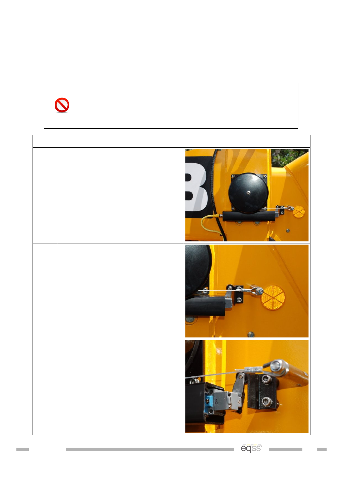
1. Drill and tap the holes for the cable
reeler according to the mounting
diagram on page 9.
Mount using the supplied M x 12
mm bolts and washers.
2. Drill and tap an M8 hole for the
cable anchor. Ensure the cable
anchor is positioned so the cable
runs in line with the boom.
Mount the cable anchor and secure
the cable to the anchor.
3. Drill and tap the M holes for the
stow switch trigger. Ensure the stow
switch is pressed when the boom is
retracted.
Mount the stow switch trigger using
the supplied M x 30 mm bolts and
17 mm standoffs.
VER: 1607211119 7 of 40
Step Description Diagram
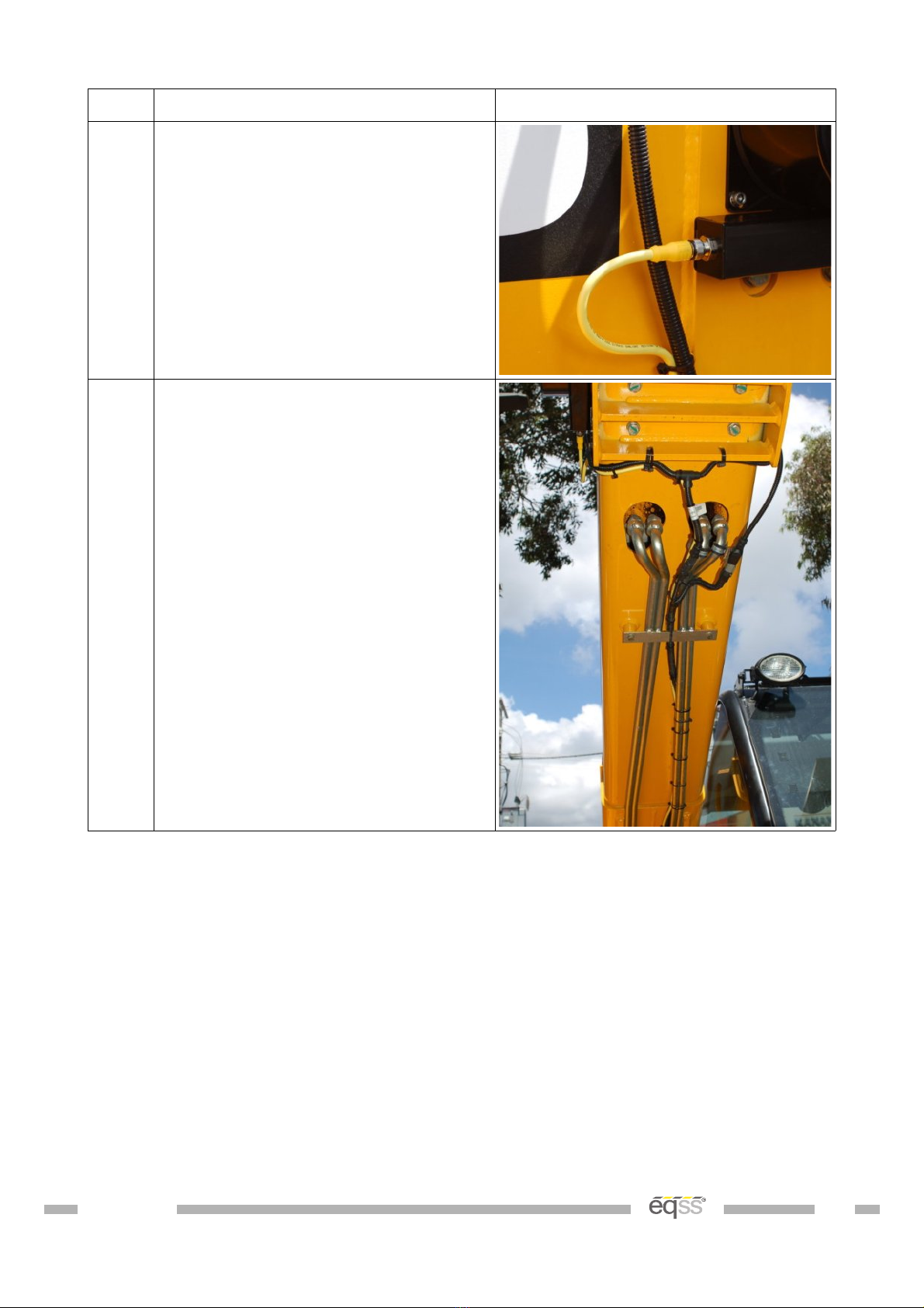
4. Connect the supplied M12 10 metre
cable (CB001027) into the cable
reeler connection.
5. Run the cable along the hydraulic
pipes running down the boom,
secure using cable ties every 150
mm to 200 mm.
Cable tie to the flexible hydraulic
hoses down to the chassis. Make
sure the cable isn't pinched or
stretched when the boom is raised
or lowered.
Run the cable towards the cabin and
cable tie with the other cables
during External Cable Completion on
page 21.
Table 2: Cable Reeler Installation
VER: 1607211119 8 of 40

Pressure Sensor Installation
The hydrauli pressure sensors are used to measure the lifting load of the telehandler.
Main Cylinder Pressure Sensors
Step Description Diagram
1. Raise the boom to approximately 40
degrees.
Support and secure the boom using
an A Frame or similar apparatus. It
must support at least 2 tons.
Apply the handbrake and insert
chock under wheels.
Release the blanking cap on the
hydraulic tee.
Removing the blanking cap will
release the hydraulic pressure which
may result in a spray of oil.
Install the supplied pressure sensor
and ensure it is tightly sealed.
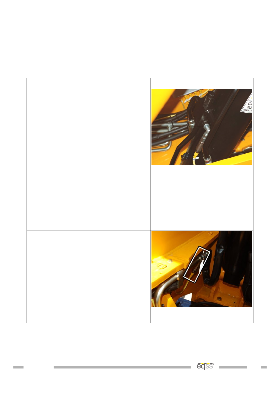
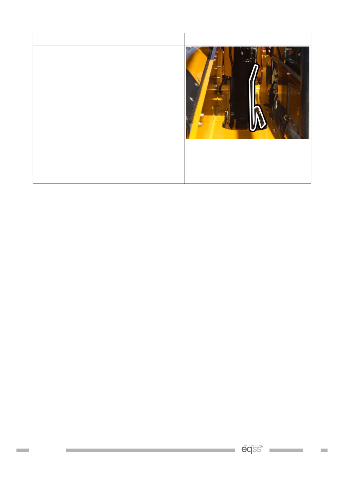
2. Install the tee connector and
pressure sensor into the rod of the
main lift cylinder, where the flexible
hose is connected to the solid hose
on the chassis under the lift
cylinder.
Start the machine, pressurise the
boom and check for leaks.
View from under the main lift
cylinder
VER: 1607211119 10 of 40
Step Description Diagram
3. Connect the supplied M12 4 metre
cables (CB00102 ) into each of the
pressure sensors.
Cable tie the head pressure sensor
cable to the flexible hydraulic hoses
connected to the main lift cylinder.
Make sure the cable isn't pinched or
stretched when the boom is raised
or lowered.
Run the cables towards the cabin
and cable tie with the other cables
during External Cable Completion on
page 21.
Table 3: Pressure Manifold Installation
VER: 1607211119 11 of 40

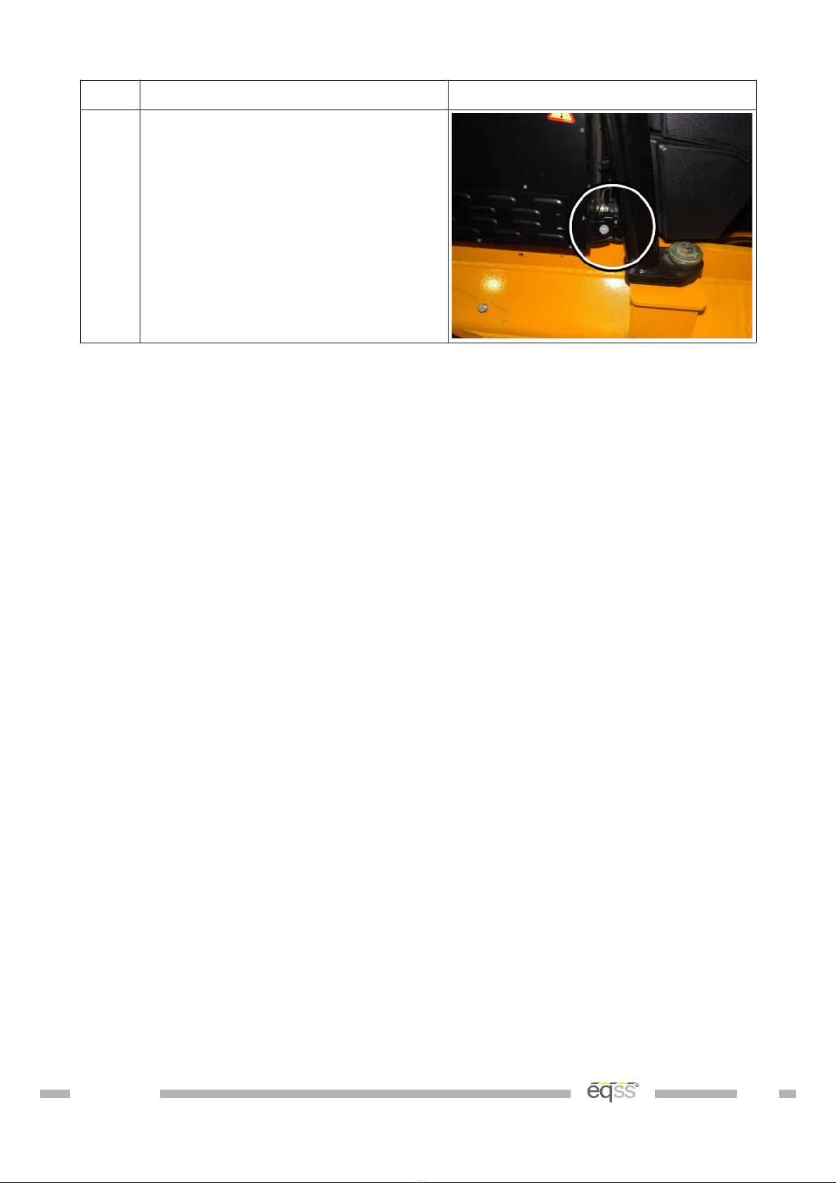
Compensation Pressure Sensors
Step Description Diagram
1. Release the cover behind the
machine.
Undo the hydraulic connection for
the head compensation into flexible
hydraulic line at the rear of the
machine.
Install the supplied tee piece and
pressure sensor in line with the
hydraulic connection.
2. Undo the hydraulic connection for
the rod compensation into flexible
hydraulic line at the rear of the
machine.
Install the supplied tee piece and
pressure sensor in line with the
hydraulic connection
Start the machine, pressurise the
boom and check for leaks.
3. Connect the supplied M12 4 metre
cables (CB00102 ) into each of the
pressure sensors.
Add both cables to 2 m of snake
tube.
Run the snake tube and cables
towards the cabin and cable tie with
the other cables during External
Cable Completion on page 21.
Table 4: Compensation Pressure Sensor Installation
VER: 1607211119 12 of 40


Reverse Camera
The rear amera video is displayed on the s reen when the ma hine is in reverse gear to
allow the operator to see behind the telehandler while reversing.
Do not disconnect the camera power connection while the
system is operating as this can damage the fuse.
Step Description Diagram
1. Drill a 31mm hole in the location
shown. Making sure to leave enough
room for a license plate
Insert the camera through the hole
and adjust the angle using the
alignment washers.
2. Connect the camera power and
signal connectors to the supplied 5m
camera cable (CB001032).
Note; The white connector is not
used.
Secure the camera cable to the
license plate light cables
Run the remainder of the cable
towards the cabin and cable tie with
the other cables during External
Cable Completion on page 21.
Table 5: Reverse Camera Installation
The camera's viewing angle may need to be adjusted once the
system is installed and the display is operational.
VER: 1607211119 14 of 40
Forward Camera
The forward amera video is displayed on the s reen when the ma hine is in forward gear
to allow the operator to see past the boom to obstru tions that would damage the right
front tyre.
Do not disconnect the camera power connection while the
system is operating as this can damage the fuse.
Step Description Diagram
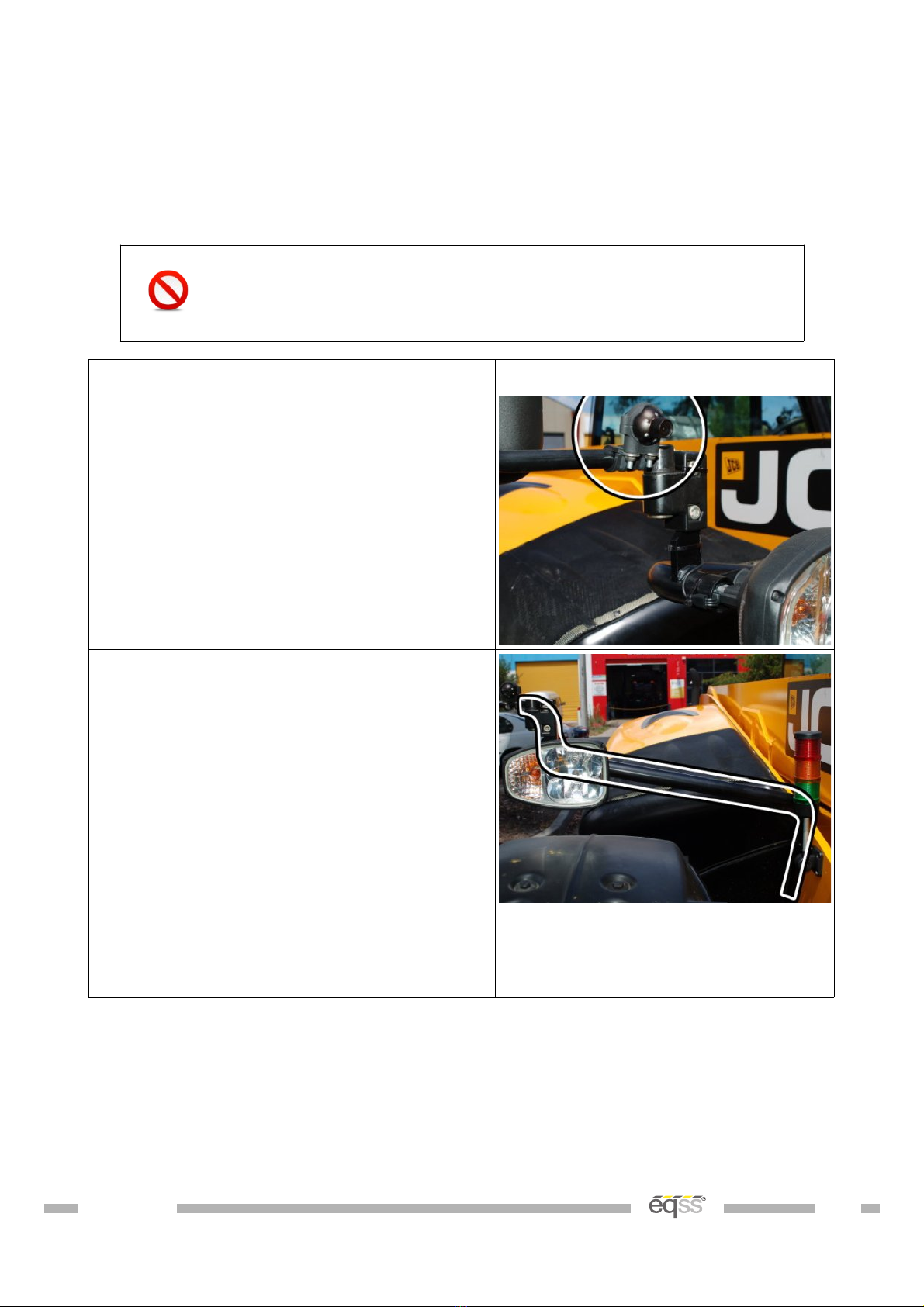
1. Mount the camera to the side mirror
using the p-clips as shown.
Secure using two M nuts.
2. Connect the camera power and
signal connectors to the supplied 5m
camera cable (CB001032).
Note; The white connector is not
used.
Run the cable along the same path
as the headlight cable, run it through
the headlight post, then under the
chassis to the side of the cabin.
Cable tie during External Cable
Completion on page 21.
Table : Forward Camera Installation
VER: 1607211119 15 of 40

Signal Light Installation
The signal light warns other workers when the telehandler is lifting loads lose to it's
maximum apa ity.
Ensure the power supply voltage is greater than 13.5V
otherwise the signal light may not illuminate correctly.
With Windshield Guard Bar
Step Description Diagram
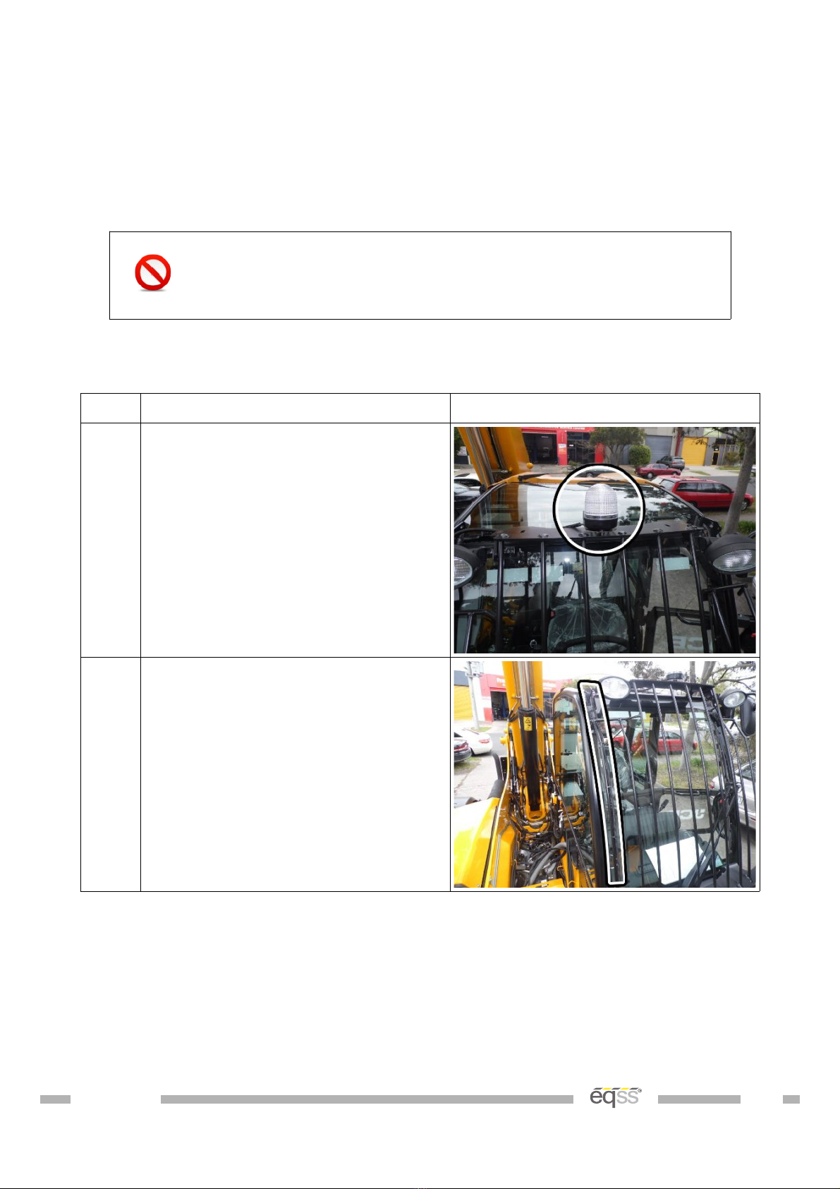
1. Mount the signal light to the top of
the front windshield guard on the
cabin.
2. Run the cable down the side of the
windshield and cable tie to the
windshield guard bar down towards
the chassis.
Table 7: Signal Light Installation With Windshield Guard Bar
VER: 1607211119 17 of 40
Without Windshield Guard Bar
Step Description Diagram
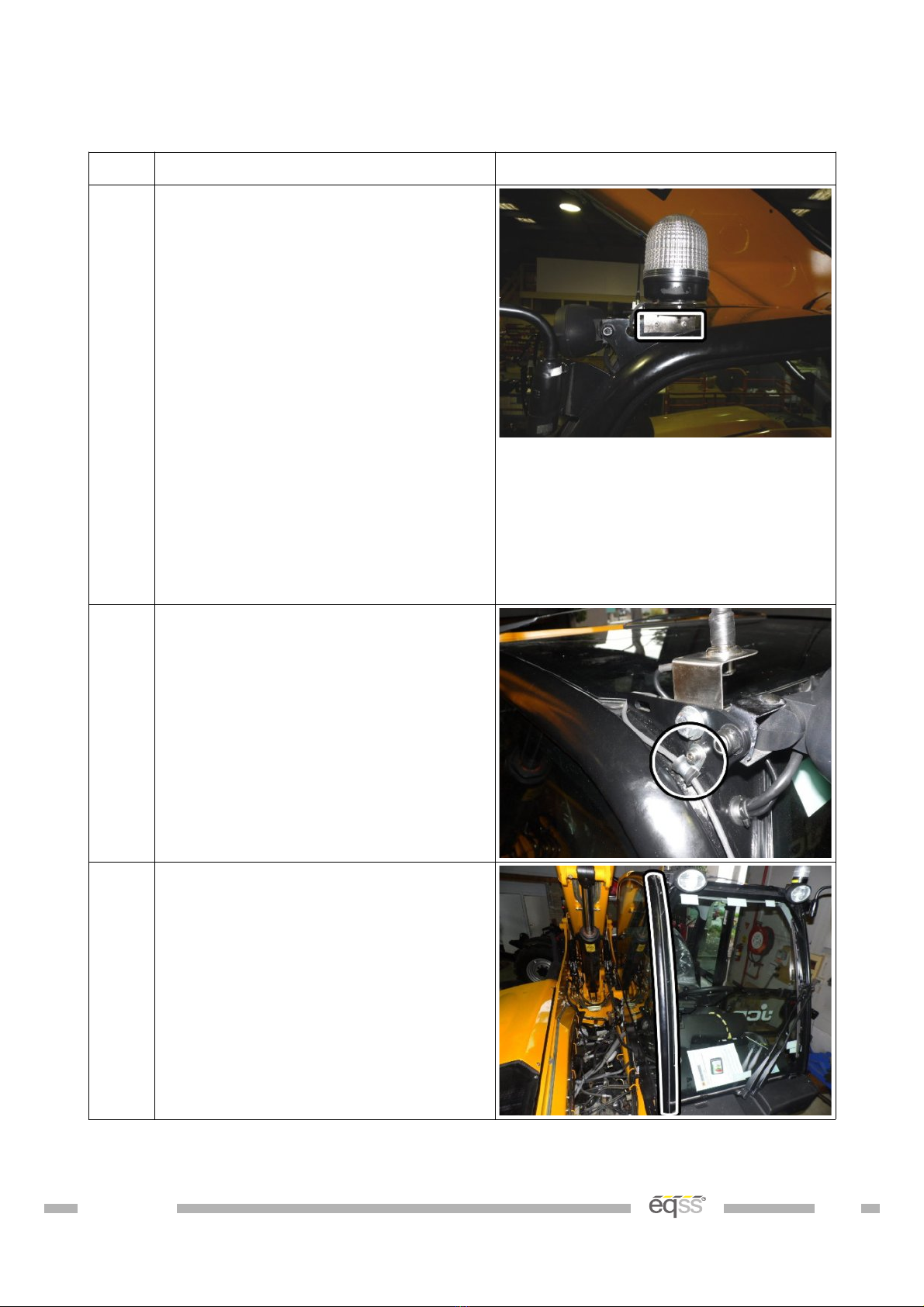
1. Remove the magnet from the bottom
of the signal light mounting bracket
and flip the signal light mounting
bracket so the mounting holes are on
the bottom.
Cut and remove 2. m of snake tube
from the end of the cable starting at
the signal light.
Drill two M4 holes to mount the
signal light bracket to the left
headlight support bracket on the
roof.
Mount using the supplied M4 bolts
and nuts.
2. Run the cable along the top of the
roof to towards the right headlight
support bracket.
Drill a single M hole to mount a
metal p-clip.
Attach the cable to metal p-clip and
secure using the supplied M bolt
and nut.
3. Run the cable down between the
edge of the windshield and cabin
frame to the base of the windshield.
Use a water proof adhesive to
ensure the cable will remain within
the gap between the edge of the
windshield and cabin frame.
VER: 1607211119 18 of 40
Step Description Diagram
4. Secure the cable to the chassis using
a cable tie.
Note: Make sure the cable is
securely tensioned, so it doesn't
move out of the groove between the
edge of the windshield and cabin
frame.
Table 8: Signal Light Installation Without Windshield Guard Bar
VER: 1607211119 19 of 40
Can Pressure Input Module (CPIM)
The CPIM is responsible for pro essing the information sent from the pressure sensors.
Accidentally swapping the pressure sensor connections will
not damage system and can be determined if the display is
showing a negative load.
Do not plug the pressure sensor cable into the far right side
boom cable. This will damage the system.
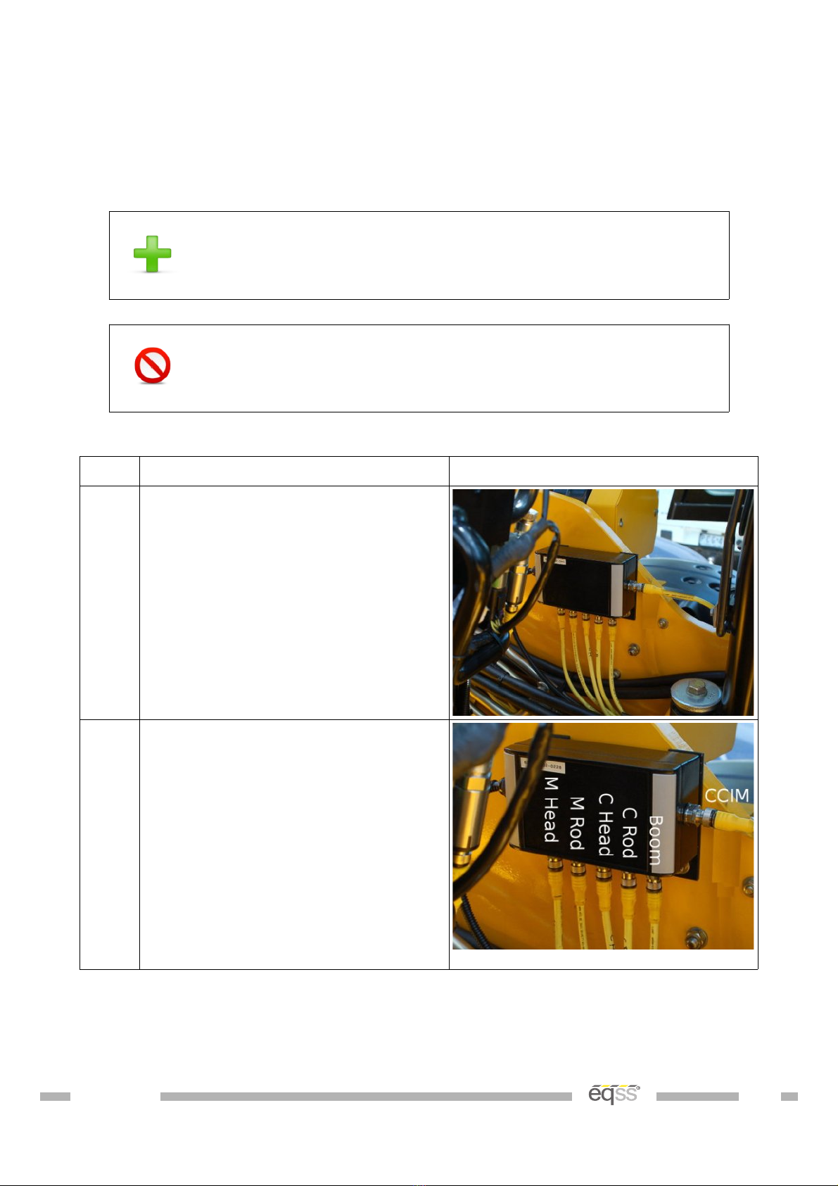
Step Description Diagram
1. Drill and tap two M8 holes for the
CPIM bracket in the chassis behind
the cabin.
Mount using the supplied M8 x
12mm bolts and washers.
2. Connect the cables for the pressure
sensors and boom cable to the CPIM
according to the picture shown.
Connect the supplied M12 4 metre
cable (CB00102 ) into the
connection out of the right side of
the CPIM for the CCIM cable.
Run the CCIM cable towards the
cabin.
Table 9: Can Pressure Input Module (CPIM) Installation
VER: 1607211119 20 of 40
Other manuals for Gen-3 LMS
11
This manual suits for next models
1
Table of contents
Other eqss Construction Equipment manuals


