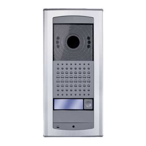
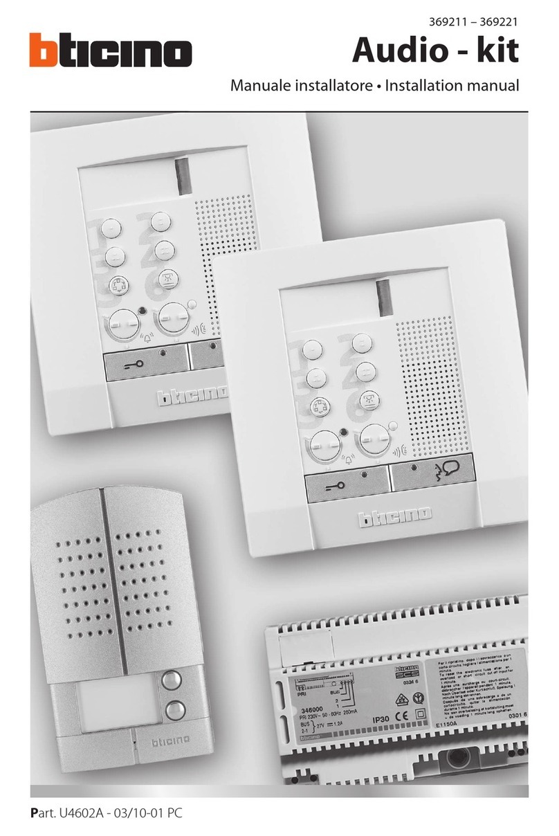
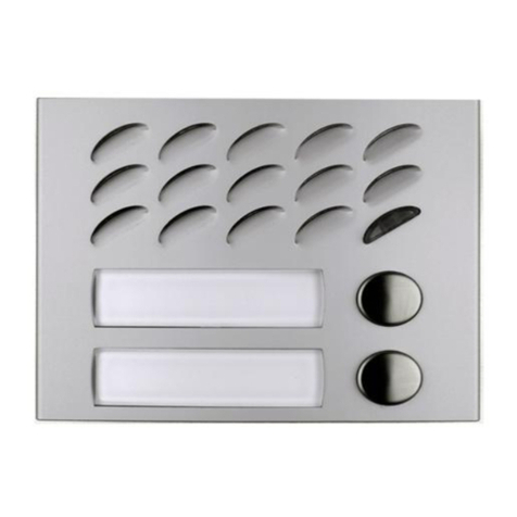
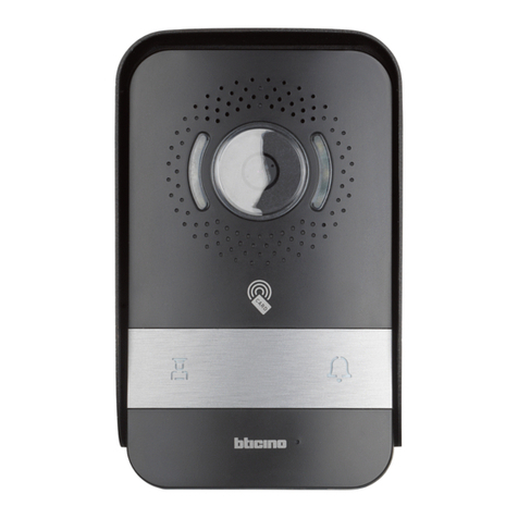
Equitel E451 User manual

Voy eco
VoIP audio intercom
VoIP audio intercomVoIP audio intercom
VoIP audio intercom
E451
E451E451
E451
Technical and installation manual
Technical and installation manualTechnical and installation manual
Technical and installation manual
IP Intercom system

This document is the technical reference of the EQUITEL module E451 for IP intercom systems.
This edition is valid for the following version
oHardware version V121
oFirmware version V1.03
© Equipos de Telecomunicación Optoelectrónicos, S.A.
Zaragoza, August 2 12.
Ed. 1.2

August 2 12 – Ed.1.2
EQUITEL – E451 Technical manual
iii
E451 Technical manual
Index
Chapter 1
Description.................................................................................................................................... 1
1.1
General description .............................................................................................................................. 1
1.1.1.
Proprietary mode ......................................................................................................................... 2
1.1.2.
SIP mode with PBX ....................................................................................................................... 3
1.1.3.
P2P-SIP mode ............................................................................................................................... 3
1.1.4.
E451 intercom block diagram ...................................................................................................... 3
1.2
Equipment elements ............................................................................................................................ 4
1.3
Audio .................................................................................................................................................... 6
1.3.1.
Loudspeaker output ..................................................................................................................... 6
1.3.2.
Microphone input ........................................................................................................................ 6
1.4
User button .......................................................................................................................................... 6
1.5
Status LED ............................................................................................................................................. 6
1.6
Power supply connector ....................................................................................................................... 6
1.7
Reset button ......................................................................................................................................... 6
1.8
Factory default values recovery ........................................................................................................... 7
1.9
Input contact connector ....................................................................................................................... 7
1.1
Output contact connector .................................................................................................................... 7
1.11
Network connectors ............................................................................................................................. 8
1.11.1.
Daisy Chain ................................................................................................................................... 8
Chapter 2
Mechanical mounting ................................................................................................................. 1
2.1
Materials and dimensions .................................................................................................................. 1
2.2
Installation .......................................................................................................................................... 11
Chapter 3
Functionality ............................................................................................................................... 13
3.1
Proprietary mode ............................................................................................................................... 13
3.1.1.
Connection with the controller .................................................................................................. 13
3.1.2.
Sending a call ............................................................................................................................. 13
3.1.3.
Audio communication establishment ........................................................................................ 13
3.1.4.
Audio communication closing .................................................................................................... 14
3.2
SIP mode with PBX ............................................................................................................................. 14
3.2.1.
SIP network basic configuration with PBX ................................................................................. 15
3.2.2.
Sending a call ............................................................................................................................. 15
3.2.3.
Call reception ............................................................................................................................. 15
3.2.4.
Audio communication ................................................................................................................ 16
3.2.5.
Closing of the audio communication ......................................................................................... 16
3.3
P2P-SIP mode ..................................................................................................................................... 16
3.3.1.
P2P-SIP network basic configuration ......................................................................................... 16
3.3.2.
P2P-SIP network communication process ................................................................................. 17
3.4
Functioning test .................................................................................................................................. 17
3.5
Audio prerecorded messages ............................................................................................................. 17
Chapter 4
Auxiliary input and output control ............................................................................................. 18
4.1
Contacts control commands............................................................................................................... 18
4.1.1.
Configuration consult ................................................................................................................. 18
4.1.2.
Output writing............................................................................................................................ 18
4.1.3.
Contacts reading ........................................................................................................................ 18
4.1.4.
Change in the inputs status ....................................................................................................... 18
4.2
Output contact activation by DTMF tones ......................................................................................... 18

August 2 12 – Ed.1.2
EQUITEL – E451 Technical manual
iv
Chapter 5
Configuration through web server ............................................................................................. 19
5.1
General information ........................................................................................................................... 2
5.2
Network configuration ....................................................................................................................... 2
5.3
Working mode configuration ............................................................................................................. 21
5.4
Audio configuration ............................................................................................................................ 24
5.5
Inputs and outputs ............................................................................................................................. 26
5.6
Credentials configuration ................................................................................................................... 27
5.7
Firmware update ................................................................................................................................ 27
5.8
Factory default and reboot ................................................................................................................ 28
Chapter 6
Maintenance ............................................................................................................................... 29
6.1
Firmware update ................................................................................................................................ 29
6.2
Factory default recovery .................................................................................................................... 29

August 2 12 – Ed.1.2
EQUITEL – E451 Technical manual
Page 1
Chapter 1 Description
1.1 General description
EQUITEL E451 is an anti-vandal IP intercom based on VoIP technology. It is especially designed to be used in
IP intercom systems.
It can be powered either through the PoE standard
(1)
, thus simplifying the unit installation and maintenance,
or by using a standard auxiliary power supply.
The most important characteristics of this equipment are:
•Double Ethernet 1 /1 Base-T/TX interface, one of them compatible with the PoE technology.
•Single channel bidirectional audio transmission, with audio quality improvements thanks to an
acoustic echo dynamic cancellation.
•Integrated SIP agent, which allows establishing a communication with external devices by means of
P2P-SIP mode or the SIP mode with a PBX.
•Calls supervision, internal operation test, contacts control and management by proprietary protocol
•One user button with one status LE.
•Electret microphone and 8 Ω loudspeaker.
•1 opto-isolate input and 1 relay output, normally open, for external connections.
•System configuration, audio messages and firmware remote update through a web server.
•Robust construction with operating temperature range from -4 ºC to +74 ºC.
•Auxiliary power supply from 9 to 14V DC.
•Consumption lower than 5 W.
•Flush or surface mounting enclosure.
(1 ) PoE (Power over Ethernet) is a technology that allows network devices to be electrically powered through the same cable used for the Ethernet network connection.
This technology is regulated in the IEEE 8 2.3af standard.

August 2 12 – Ed.1.2
EQUITEL – E451 Technical manual
Page 2
The general architecture of an intercom network, based on Voice over IP communication standards using
E451 systems, can be depicted as follows:
Figure 1. IP intercom system scheme with E451 units
Each E451 unit is connected through the Ethernet interface to a VoIP network, in which there may be a PBX,
physical SIP telephones or software based (softphone) and a controller.
By controller we refer to a computer running a software capable of communicating with the intercom E451
for management and audio transmission.
E451 has three operation modes for establishing the IP communication (see Chapter 3):
1.1.1. Proprietary mode
The EQUITEL proprietary protocol for control and communications establishment is used in the
connection between the intercom E451 and the controller. For the audio transport, we have considered a
standard VoIP protocol.
Using an industrial standard for the voice transport is important, since it eases the voice communication
establishment between an E451 unit and the standard IP telephones.
Apart from establishing the audio communication, using this protocol allows adding particular
functionalities of these systems such as: incidents recording (alarms, calls, etc) and constant knowledge of
its status, even if the SIP protocol is used for the communication initiation.
In this mode, it is possible to use the demo application supplied by EQUITEL to control several E451 and
send audio from a computer.

August 2 12 – Ed.1.2
EQUITEL – E451 Technical manual
Page 3
1.1.2. IP mode with PBX
E451 intercom incorporates a SIP agent that allows sending and receiving calls directly from an IP phone
using the SIP protocol
(2)
through a PBX, should the equipment have been configured to work in this mode.
A controller is optional in this mode, although by using one it would be possible to supervise the calls
established through the SIP protocol, in order to register them.
1.1.3. P2P- IP mode
This mode is similar to the previous one. However, in this case we can use the SIP protocol without the
need of a PBX, using “peer-to-peer” (P2P) strategies to initiate sessions.
We must take into account that the supervision control performed by a PBX is lost (expiry time,
forwarding calls, etc)
Should the auxiliary input or output be used, it is necessary a control software to remotely manage the
E451 intercom input or output, regardless the working mode chosen for the audio communication.
1.1.4. E451 intercom block diagram
Figure 2. E451 block diagram
E451 intercom contains both the electronic board and the interface passive elements with the user:
microphone, loudspeaker, user button and status LED.
(2) SIP is a protocol for establishing communications, defined in the RCF 3261 standard, and quite employed nowadays in IP telephony systems.
ATTENTION!

August 2 12 – Ed.1.2
EQUITEL – E451 Technical manual
Page 4
The equipment can be PoE powered. This allows the unit to be powered using the same cable employed
for the network connection. With this, we avoid the need of using sockets in those places where the
intercom E451 is installed.
Furthermore, in the case of not having a PoE Ethernet, it is possible to use a +9 to +14 V DC auxiliary
power supply.
Optionally, the unit can be powered at +24 V DC. If so, please contact EQUITEL commercial department or
in support@equitel.es
1.2 Equipment elements
E451 is housed in a flush or surface mounting enclosure with anti-vandal front and push-button, that confers
a high degree of ruggedness. In Chapter 2 we explain in detail the E451 mechanical mounting for a proper
installation.
We list below the unit most important elements, and in the Figure 3 and Figure 4 it is shown where they are
placed:
Element Description
1 Laudspeaker
2 Microphone
3 User button
4 Status LED
5 Power supply connector
6 Reset push button
7 Push button for factory default configuration recovery
8 Input contact connector
9 Output contact connector
1 Network connector (ETH)
11 PoE network connector (ETH/PoE)
12 ON LED
13 Network LINK LED (ETH)
14 PoE network LED (ETH/PoE)
15 RESET LED

August 2 12 – Ed.1.2
EQUITEL – E451 Technical manual
Page 5
Figure 3. E451 front elements
Figure 4. E451 inner elements
13
14
12 5
7
6
9
15
8
10
11
1
3
2
4

August 2 12 – Ed.1.2
EQUITEL – E451 Technical manual
Page 6
1.3 Audio
1.3.1. Loudspeaker output
The audio codec output is connected to an amplifier capable of providing up to 1.1 W over an 8 Ω load.
The loudspeaker is connected at the +6dB gain amplifier output ( in Figure 3), with an impedance of
8Ω and 3W input nominal power.
1.3.2. Microphone input
The audio input is composed by an “electret” type microphone ( in Figure 3) and a +1 dB gain
preamplifier.
With this, the signal range that can be captured by the microphone and delivered to the audio codec is
much higher. This provides a higher flexibility when selecting the audio volume.
1.4 User button
This button ( in Figure 4) is associated to one microprocessor input. If configured in the Proprietary Mode,
the unit requests a call to the control center when pressing it. In the case of using the SIP protocol, this
button has a triple functionality: call, answer the call and hang up.
1.5 tatus LED
E451 has a visual indicator of the audio communication status:
•When ringing (input or output call): LED blinks.
•Open bidirectional audio channel: LED on.
•Closed audio channel: LED off.
This status LED ( in Figure 4) is placed in the same call button.
1.6 Power supply connector
In the absence of a PoE Ethernet network to power the unit, E451 can be powered with an auxiliary DC power
supply between +9 and +14 volts. It can give a minimum of 5 W and .5 mA.
The auxiliary power supply is made through a 2 pins-pole ( in Figure 4).
Pin ignal Description
1 VDC Power (9 .. 14 V)
2 GND Ground
As a protection measure, the unit has an internal 2.5A rearming fuse.
When the unit is correctly powered, the ON indicator ( in Figure 4) should flash.
1.7 Reset button
It may be necessary to reset the unit in case of wrong functioning. If so, simply press the reset button ( in
Figure 4). Its associated LED is marked as in the Figure 4.
Furthermore, it is possible to remotely reset the unit through the web (see Chapter 5.8 ).
15
6
12
5
4
3
2
1

August 2 12 – Ed.1.2
EQUITEL – E451 Technical manual
Page 7
1.8 Factory default values recovery
To recover the system factory default values such as network configuration, access password, working mode,
audio parameters…please keep pressed the recovery button for 6 seconds ( in Figure 4).
1.9 Input contact connector
The input contact is “normally open” between the 2 pins male connector terminals ( in Figure 4), with the
following pin-out:
Pin ignal Description
1 IN+ Input
2 IN- Ground for input
The input contact activation is carried out by joining the corresponding line (IN+) with the common (IN-).
The opto-isolated input internal electrical scheme of is shown in the following figure:
Figure 5. Electrical scheme of the input contact
1.10 Output contact connector
The output contact is a free-of-voltage dry contact between the two male connector terminals ( in Figure
4):
Pin ignal Description
1 OUT_A Output A
2 OUT_B Output B
This contact supports a maximum current of 1A.
The internal structure of the “normally open” relay output is the one shown in Figure 6.
9
8
7

August 2 12 – Ed.1.2
EQUITEL – E451 Technical manual
Page 8
Figure 6. Output contact Electrical scheme
1.11 Network connectors
E451 has two Ethernet 1 /1 Base-T/TX interfaces (Half or Full-Duplex) with automatic detection ( and
in Figure 4), supporting MDI and Auto MDIX.
Auto MDIX interface changes automatically from MDI to MDI-X and vice versa, allowing the connection of any
cable (straight or cross) regardless the direct connection to a computer or to a switch/hub.
E451 can be PoE powered, and the connector is named as “ETH/PoE” ( in Figure 4). When the unit is
correctly powered, the ON indicator ( in Figure 4) must light.
Each one of the two network connectors has a LED indicating the correct connection status. The Link LEDs for
the connector “ETH” and for “ETH/PoE” are the ones with the numbers and respectively in Figure 4.
1.11.1. Daisy Chain
E451 intercoms can be connected using a Daisy Chain configuration (Figure 7) using their two RJ-45
connectors. This way we avoid the use of an external switch. However, in this case redundancy is lost:
should any of the E451 disconnect for any reason, all the successive intercoms will remain inaccessible.
Furthermore, it must be taken into account that E451 are not PoE injectors but passive devices. Therefore,
in a Daisy Chain only the unit connected to the PSE
(3)
will be powered through the network cable and the
others will have to be powered through an auxiliary power supply.
(3) PSE (Power Sourcing Equipment) are the units supplying power, such a s PoE switch.
14
13
12
11
1
1
10

August 2 12 – Ed.1.2
EQUITEL – E451 Technical manual
Page 9
Figure 7. E451 Daisy Chain connection

August 2 12 – Ed.1.2
EQUITEL – E451 Technical manual
Page 1
Chapter 2 Mechanical mounting
This chapter is devoted to the mechanical aspects of the equipment for its installation afterwards.
2.1 Materials and dimensions
E451 is composed of main pieces:
1. Galvanized steel sheet box. Dimensions: 2 x 12 x 56 mm.
2. Stainless steel box. Dimensions: 22 x 14 x 1.5 mm.
3. Aluminum middle plate. Dimensions: 22 x 14 x 2 mm.
The front elements are anti-vandal: button with LED and screws.
Figure 8. E451 external dimensions

August 2 12 – Ed.1.2
EQUITEL – E451 Technical manual
Page 11
2.2 Installation
E451 is supplied with the box closed. Therefore, when installing it first of all we have to remove the 4 anti-
vandal screws having a point for a special screw-driver ( in Figure 9). This way, the equipment is separated
in two pieces (see Figure 9):
PIECE 1:
Electronic board and loudspeaker attached to the aluminum middle plate. The latter is fastened to the
stainless steel front and is locked with the anti-vandal button crossing both of them. Furthermore, it is
included the microphone with a wrapping that avoids harmful vibrations for the audio quality.
PIECE 2:
Flush-mount sheet box. It has to be fixed by 4 wall bolts, two at each side. It has 5 further holes for an easy
and safe cabling.
Figure 9. E451 outer case opening
Element Description
1 Point for 2-holes anti-vandal security screw
2 Anti-vandal security screw
3 Electronic PCB
4 PCB fastening base
5 Loudspeaker
6 Microphone with its isolation
7 Anti-vandal button with LED
8 Holes for cable duct
9 Anchors fastening
8
9
PIECE 2
4
6
7
5
PIECE
1
3
2
1
1

August 2 12 – Ed.1.2
EQUITEL – E451 Technical manual
Page 12
In order to install the sheet metal box, we have to do an opening in the wall selected for mounting the
intercom E451. The box must be plastered at the surface level and placing it straight since when mounting it
there will be no more orientation possibilities.
The necessary cabling for the E451 Ethernet and power connections must be carried out through the holes in
the box intended for this purpose ( in Figure 9).
Once the power and Ethernet connections are made (explained in the points 1.6 and 1.11 espectively), the
equipment must be locked by screwing again the 4 anti-vandal screws as shown in Figure 1 ).
Figure 1 . Wall mounting
Ethernet network
and power cabling
8

August 2 12 – Ed.1.2
EQUITEL – E451 Technical manual
Page 13
Chapter 3 Functionality
In this chapter we will detail the IP intercom System functionalities based on the modules E451.
We will explain separately each one of the possible operation modes in which E451 can be configured; the event
chains taking place in each case; the pre-recorded audio messages used,…
3.1 Proprietary mode
3.1.1. Connection with the controller
In this mode, the communication establishment between E451 and the controller is made through an
EQUITEL proprietary protocol. It is described in the document “Communications protocol E4 EQUITEL
family”, where it is detailed all the information regarding the communication functioning between the
E451 and the controller.
E451 behaves as a TCP server in the port 7000 and accepts one single client connection at the same time.
3.1.2. ending a call
Once the user button is activated, the process of sending the call to the control centre begins as per the
following sequence:
1. E451 sends a TCP message to the controller indicating that the push button has been activated
and requests a call, “DEMCALL”.
2. The controller will answer with the corresponding ACK, in this case “ACK_DEMCALL”.
3. When the previous ACK message is received, E451 begins to play the prerecorded message
“calling tone”, indicating “called received” and will remain like that for a maximum of 1 minute
waiting to receive the audio activation message from the central. While playing, the status LED
(see Figure 3) will light intermittently.
4. In case of not receiving the ACK, or if one minute has passed by and the audio has not been
activated, E451 will play twice the pre-recorded message “offline tone” which indicates
“destination not available” and the LED will turn off.
3.1.3. Audio communication establishment
When a controller wants to establish audio communication with E451, either as a result of call or
asynchronously, the former sends a message of “STARTAUDIO” to E451, in which it is included the IP
address and the audio destination port.
The moment E451 receives this order, it opens the port 30000 to listen to the incoming RTP packets and
sends what it generates to the indicated address and ports.
E451 answers the controller with the corresponding ACK (“ACK_STARTAUDIO_OK”,
“ACK_STARTAUDIO_NOK”), indicating whether it has been possible to activate the audio or not.
If the audio activation has been correctly made, the LED will light and will remain like this as long as the
audio keeps open.
Should error communications arise, in order to avoid E451 to have the audio permanently activated the
controller sends refresh orders. Every time the order “STARTAUDIO” is received, the audio
communication will remain active for a maximum of 2 minutes.
The audio communication with E451 uses the RTP protocol with the codification G.711-A and a sampling
frequency of 8 kHz.

August 2 12 – Ed.1.2
EQUITEL – E451 Technical manual
Page 14
3.1.4. Audio communication closing
To close an audio communication previously established, the controller must send the message of
“STOPAUDIO”.
E451 will send the corresponding ACK (“ACK_STOPAUDIO_CLOSED”, “ACK_STOPAUDIO_NOCLOSED”). This
way, the controller will be able to know if the unit has the audio closed or not.
The LED switched off indicates that the audio circuits are correctly closed.
3.2 IP mode with PBX
E451 incorporates a SIP agent that allows receiving and making calls directly to SIP devices, and even to
analogue or mobile devices if the appropriate PBX is used.
This protocol encompasses the establishment, modification and finalization management of multimedia
services interchange sessions among several participants through digital networks.
SIP is a very complex protocol since it covers several aspects, and in E451 we have given the application of
VoIP calls management. We have implemented a small part that allows answering and making calls to the
configured device by means of a “push-to-call” function associated to the user button (see Figure 3).
E451 may register in a SIP PBX as another extension to make and receive calls. Furthermore, it supports calls
forwarding, so that (for example) the call received in an intercom can be forwarded to another extension.
Figure 11. Basic network for a E451 using IP
Through this system, it would be possible to implement an IP intercom network by using E451 units with the
need of a controller; it is simply required a SIP PBX and one or several telephones.

August 2 12 – Ed.1.2
EQUITEL – E451 Technical manual
Page 15
However, optionally it can be added a controller to this network (see Figure 11), consisting on a computer
running the appropriate software. It is possible to use a demo application supplied by EQUITEL. In the working
mode with SIP protocol, it just supervises the established calls in order to register them and controls the auxiliary
outputs and inputs. (see points 1.9 and 1.1 ).
3.2.1. IP network basic configuration with PBX
The procedure to configure the network using E451 units and SIP mode with a PBX is as follows:
1. Configure the PBX so as to register as many extensions as E451 units and telephones you wish to
use.
2. Configure the telephones so that they may be registered in the PBX with the assigned extension.
It is very important the used telephones to have the capacity of using the audio codec G711-A,
which is the one used by E451 intercoms.
3. Configure the E451 units so that they may be registered as well in the PBX with the extension
assigned to each one.
4. In each E451, configure the extension of the number to which the intercom will call when
pressing the external button. The call can be forwarded to another telephone (should E451 not
answer it) by configuring the PBX.
5. When all the units are configured, we must verify that all the units are actually registered in the
PBX and thus they are capable of communicating.
As we will see in the following chapters, the user button has a triple functionality: call, answer and hung
up.
3.2.2. ending a call
When the user button is activated and E451 is correctly registered in the PBX, begins the communication
establishment by using the SIP protocol:
1. If the device to which it is desired to call (telephone, E451…) is registered, available and accepts
the same audio codification as E451, the latter begins to play the prerecorded message “calling
tone”, which indicates “call received at destination”. It remains like that till the receiver answers
or the waiting time configured in the PBX has expired. The status LED will blink at the same time
the tone is being played.
2. Should E451 or the destination telephone not be registered, or if a problem with the
communication has occurred (the destination is busy; the audio communication is not
compatible), or if the waiting time for accepting the call has expired, the “offline tone”
prerecorded message will be played twice, indicating “destination not available” and the LED
will turn off.
3. Simultaneous to this process of communication establishment, and if there is a controller
correctly connected to the network, E451 sends TCP messages indicating the facts that are
taking place: send call request, “DEMCALLSIP”, call request to the destination indicated in the
message, “OUTCALLRINGING”.
4. If, for whatever the reason, E451 emits the “offline tone” message, it informs the controller of
the failure to the communication establishment with the message “DISCONNECTEDCALL”.
3.2.3. Call reception
Any of the SIP telephones can communicate with any of the E451 units, and any E451 unit can
communicate with another E451, as long as they are correctly registered in the PBX. Simply by calling the
corresponding extension (in the case of the telephone) or by configuring the receiver’s extension in the
E451 that makes the call:

August 2 12 – Ed.1.2
EQUITEL – E451 Technical manual
Page 16
1. When an E451 receives a request for establishing the communication and it has detected no
problems (such as audio codification not supported by E451, line engaged,...), E451 begins to
play the prerecorded message “ring tone” which indicates “incoming call received” and remains
like that until the communication establishment is confirmed (by pressing the user button or, if
the automatic answer is configured, till the configured time passes by); or till the waiting time
has expired (configured in the PBX). The LED blinks while the tone is being played.
2. E451 sends a TCP message to the controller, should there be anyone connected, showing an
income call request, “INCALLRINGING”, and informing furthermore about the audio
communication establishment with the message “CONNECTEDCALL”.
3. If, due to any reason, this call is rejected by E451, it informs the controller with the message
“DISCONNECTEDCALL”.
3.2.4. Audio communication
Once a call, initiated by any of the links, progresses correctly, E451 opens the audio channel to listen to
the incoming RTP packets and to send what it generates.
The audio communication using E451 uses the RTP protocol with the codification G.711-A and a sampling
frequency of 8 kHz.
As long as the intercom is in use, that is, while the audio is open, the LED will be lighting.
3.2.5. Closing of the audio communication
An audio communication previously established can be finished by any of the links. In the case of E451 the
connection is cut by pressing the user button.
In this case, if the audio deactivation has been correctly made, the status LED will turn off.
3.3 P2P- IP mode
This working mode is quite similar to the previous one, with the exception that it is not necessary the use of a
PBX to make the communication establishment.
Once the destination extension is configured in the E451, it is possible to make and receive calls with other IP
devices not requiring the registration in a PBX, as well as to make calls directly among the E451 intercoms.
The main drawback of working in this mode instead of SIP with PBX, explained in the point 3.2 , is precisely
the absence of PBX, which allows managing the communications with surveillance tasks in the links; calls
forwarding, etc.
3.3.1. P2P- IP network basic configuration
The procedure for configuring the network using E451 and P2P-SIP mode is as follows:
1. Configure the IP telephone not requiring to be registered in a PBX: you have to assign it its own
extension and the data required to make a call
(4)
. It is very important the telephone to have the
capability of using the audio codec G711-A, since it is the one used by E451 intercoms.
2. Configure the E451 units by assigning one extension to each one.
3. In each one of the E451 models, configure the extension and the IP address of the device to
which it is required to call in a “push-to-call” application. In this working mode, it is not possible
to forward the call.
4. Should all the equipments be correctly configured, they are already capable of communicating
among them.
(4) The goal of this document is not to explain the configuration of the different IP telephones available in the market; please refer to the manufacturer for this purpose.
Table of contents
