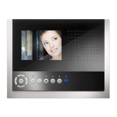
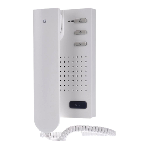
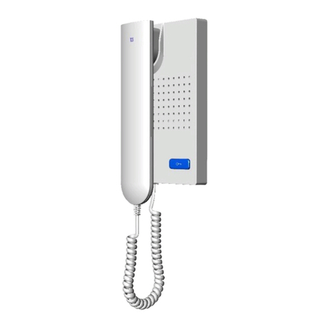
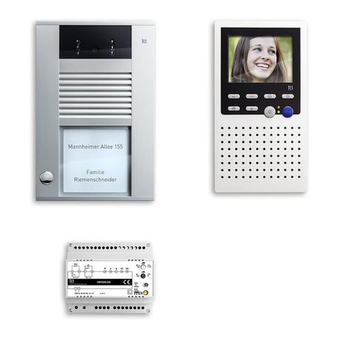
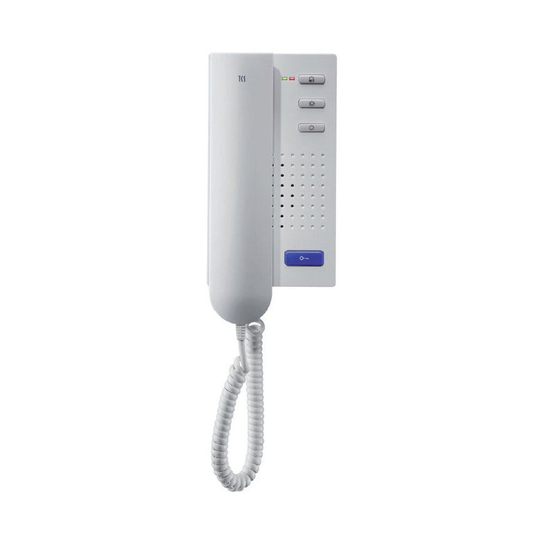
TCS IMM2500 User manual

TCS TürControlSysteme AG, TCS Hotline Germany: +49 41 94/ 9 88 11 88 Subject to technical changes.
FAX: +49 41 94/ 9 88 129 Mail: hotline@tcsag.de PI_IMM2500 1A
Product information
Indoor station with special functions
for hands-free talking
IMM2500

2 09/2013
TCS TürControlSysteme AG, TCS Hotline Germany: +49 41 94/ 9 88 11 88 Subject to technical changes.
FAX: +49 41 94/ 9 88 129 Mail: hotline@tcsag.de PI_IMM2500 1A
Table of contents
Scope of delivery .................................................................................................................3
Safety instructions................................................................................................................4
Intended use........................................................................................................................5
Short description..................................................................................................................5
Basic module....................................................................................................................5
Module with special functions...........................................................................................5
Call functions................................................................................................................6
Surveillance functions...................................................................................................6
Signal functions ............................................................................................................6
Device overview...................................................................................................................7
Technical data .....................................................................................................................7
Indication and operating elements.......................................................................................8
Basic module....................................................................................................................8
Module with special functions...........................................................................................8
Installation............................................................................................................................9
Montageort auswählen.....................................................................................................9
mounting height..............................................................................................................10
Install the lower cover.....................................................................................................10
Connect the basic module..............................................................................................10
Connect the external push button...................................................................................11
Snap-on the upper covers of the modules......................................................................11
Open the device.............................................................................................................11
Notes on voltage supply.................................................................................................12
Wiring diagram...............................................................................................................12
Connection diagram.......................................................................................................12
Notes on LSA-terminal points.........................................................................................12
Commissioning ..................................................................................................................13
Settings..............................................................................................................................13
Factory settings..............................................................................................................13
Button assignment......................................................................................................13
Pre-adjusted times......................................................................................................13
Set the ring tone volume for door calls...........................................................................13
Set the sensitivity of the motion sensor..........................................................................13
Adjust the microphone sensitivity for acoustic room surveillance...................................14
Ring tone selection.........................................................................................................14
Programming.....................................................................................................................15
Legende zur Programmierung........................................................................................15
Basic principle................................................................................................................15
Programming the basic module......................................................................................15
Programming the special functions ................................................................................18
Reload basic setting of the special function module...................................................20
Train radio sensors.........................................................................................................21
Programming the basic module with the Service Device TCSK-01................................22
Notes for configuring with configo ™ .................................................................................23
Select door call signalling by motion sensor...................................................................23
Set the response delay time of the motion sensor .........................................................23
Configure the external push button ................................................................................23
Only for systems with central.............................................................................................24
Configure call and announcement groups......................................................................24
09/2013 3
TCS TürControlSysteme AG, TCS Hotline Germany: +49 41 94/ 9 88 11 88 Subject to technical changes.
FAX: +49 41 94/ 9 88 129 Mail: hotline@tcsag.de PI_IMM2500 1A
Listen-in and speaking-into rooms (TTN function)..........................................................24
Labelling the function keys ................................................................................................24
Cleaning ............................................................................................................................25
Conformity .........................................................................................................................25
Information on disposal......................................................................................................25
Warranty............................................................................................................................25
Accessory..........................................................................................................................26
Build in a radio receiver board........................................................................................26
Conformity .........................................................................................................................26
Information on disposal......................................................................................................27
Warranty............................................................................................................................27
Important note for the installer...........................................................................................28
Service...............................................................................................................................28
Scope of delivery
1 x indoor station IMM2500
(lower cover, upper cover basic module, upper cover special functionality module)
Product information
instruction manual

4 09/2013
TCS TürControlSysteme AG, TCS Hotline Germany: +49 41 94/ 9 88 11 88 Subject to technical changes.
FAX: +49 41 94/ 9 88 129 Mail: hotline@tcsag.de PI_IMM2500 1A
Safety instructions
!
Mounting, installation, commissioning and repair of electronic devices have to be car-
ried out only by qualified electricians!
For working on systems with a main connection of 230 V alternating voltage, the safety
regulations according to DIN VDE 0100 must be observed.
When installing TCS:BUS systems the general safety regulations for telecommunication
systems according to VDE 0800 must be observed.
separated guidance of heavy and low current lines,
minimum distance of 10 cm in case of a common conduit,
use of separators between heavy and low current lines within shared cable ducts,
use of standard telecommunication lines, e.g. J-Y (St) Y with 0.8 mm diameter,
already existing lines (modernisation) with deviating cross-sections can be used in
compliance with the loop resistance.
!
With suitable measures to protect against lightning, it has to be ensured that a voltage
of each 32 V DC is not exceeded at the TCS:BUS wires a and b.
The indoor station IMM2500 must not be used in call systems according to DIN
VDE 0834 and EN50134.
According to DIN 77800, a separate safeguard for emergency calls has to be in-
stalled.
A system equipped with an indoor station IMM2500 is not an emergency call sys-
tem according to the above mentioned standards.
The system equipped with an indoor station IMM2500 must not be used in life-
saving or life-sustaining systems.
Further, the combination of system parts which fulfill the above mentioned
standards is not permitted.

09/2013 5
TCS TürControlSysteme AG, TCS Hotline Germany: +49 41 94/ 9 88 11 88 Subject to technical changes.
FAX: +49 41 94/ 9 88 129 Mail: hotline@tcsag.de PI_IMM2500 1A
Intended use
The application supports people living in their home environment and who have the possi-
bility to contact a call central located within the residential unit. Also suitable for further ap-
plications in the private area such as room surveillance, announcements, etc.
!
The indoor station IMM2500 must not be used in call systems according to DIN
VDE 0834 and EN50134.
According to DIN 77800, a separate safeguard for emergency calls has to be in-
stalled.
A system equipped with an indoor station IMM2500 is not an emergency call system
according to the above mentioned standards.
The system equipped with an indoor station IMM2500 must not be used in life-
saving or life-sustaining systems.
Further, the combination of system parts which fulfill the above mentioned stand-
ards is not permitted.
The indoor station is suitable for the operation within TCS audio systems and combined
audio / video systems.
The IMM2500 is suitable for surface-mount.
With a desktop accessory, the indoor station can be operated on a desk.
Short description
Basic module
duplex communication, handset
light switch button
blue door release button with floor door release function (can be activated)
function key (ex works allocated with control function) with alternative allocation (can be
activated) internal call, door release automatic, call diversion
ring tones can be adjusted by the resident, 13 ring tones can be selected
acoustic call distinction between 2 doors, floor call (flat door) and internal call
ring tone volume can be adjusted manually
ring tone mute with optical indication
optical indication of door calls
optical display of a busy line in case of an established voice connection
one parallel call can be activated
audio privacy function and automatic call cut-off
Module with special functions
3 coloured buttons (red, yellow, green) for the optional sending of different control func-
tions or internal calls
indication for function and internal call 3 LEDs for status indication, allocated to the but-
tons
labeling field

6 09/2013
TCS TürControlSysteme AG, TCS Hotline Germany: +49 41 94/ 9 88 11 88 Subject to technical changes.
FAX: +49 41 94/ 9 88 129 Mail: hotline@tcsag.de PI_IMM2500 1A
Call functions
internal call to 3 call destinations can be configured
call diversion can be configured
connection terminal for external push button
can be extended with radio receiver board (article number 0022930), controlled by radio
sensor, 1-channel, wristband (article number: 0022931), or radio sensor, 1-channel,
necklace (article number: 0022932)
Surveillance functions
motion sensor to detect longer breaks in activity - sends control function after a deter-
mined period of time (15min-63h, can be deactivated), sensitivity can adjusted
microphone for room surveillance, sensitivity can be adjusted
listen-in and speaking-into rooms: can be realised only in combination with the user
program call central PCSWxxxx or concierge stations PFSxx-EN.
Signal functions
announcement function can be realised only in combination with the user program call
central PCSWxxxx or concierge stations PFSxx-EN
optical signalling of incoming calls and announcement via bright LEDs which are inte-
grated in the motion sensor

09/2013 7
TCS TürControlSysteme AG, TCS Hotline Germany: +49 41 94/ 9 88 11 88 Subject to technical changes.
FAX: +49 41 94/ 9 88 129 Mail: hotline@tcsag.de PI_IMM2500 1A
Device overview
Technical data
supply voltage: +24 V ± 8 % (via supply unit)
housing: plastics
dimensions (in mm): H 148 x W 172 x D 27
weight: 430 g
acceptable ambient temperature: 0 °C ... +40 °C
degree of protection: IP 30
input current standby (3-wire operation) I(a) = 0.42 mA, I(P) = 12.2 mA
max. input current: I(Pmax) = 87.7 mA
3-wire technique necessary!
indication call OFF
(red LED)
indication additional
functions (green LED)
door release
button
function key
light switch button
call OFF-button
ring tone volume
control
loudspeaker
button RED
motion sensor and
door call signalling
(red)
Basic module
door commu-
nication
Module with
special functions
button labelling
(labelling strip with
cover)
microphone
button YELLOW
button GREEN
Anzeigen (rot)
control microphone
sensitvity*
control for motion sensor
sensitivity*
speech button
* below the key labelling

8 09/2013
TCS TürControlSysteme AG, TCS Hotline Germany: +49 41 94/ 9 88 11 88 Subject to technical changes.
FAX: +49 41 94/ 9 88 129 Mail: hotline@tcsag.de PI_IMM2500 1A
Indication and operating elements
Basic module
Speech button
speaking to the door
end communication
○
function key
in the basic module
pre-setting ex works: control function 8
alternative allocation (can be activated)
internal call (to the indoor station),
door release automatic
call diversion 1
ring tone selection internal call (from indoor station)
indication additional
functions (green)
call, communication is activated
door release automatic or call diversion
door status indication
light switch button
switching lights
ring tone selection floor call (from the flat door)
call OFF-button
ring tone stopper
programming
display call OFF (red)
ON: call OFF is activated
Blinks: indication speech channel is busy
door release button
open the door
trigger light switch function (if light switch function is ac-
tivated in the front-door station)
ring tone selection door call from front-door station
ring tone volume con-
trol
ring tone volume can be adjusted continuously
Module with special functions
button RED, configurable
acoustic room surveillance on/off
send internal call 3
send control function 10 (=factory setting)
indication for button RED
ON: acoustic room surveillance is activated
Blinks: in case of an incoming internal call
from an indoor station, send internal call and
when triggering the room surveillance (here
the internal call is sent) and sending internal
call 3
(control function 10: no indication)
button YELLOW, configurable
Send control function 1 and 2 (alternating), in
combination with a PC central the function
can be used, e.g. as indication for pres-
ence/absence.
send internal call 2
switching lights (=factory setting)

09/2013 9
TCS TürControlSysteme AG, TCS Hotline Germany: +49 41 94/ 9 88 11 88 Subject to technical changes.
FAX: +49 41 94/ 9 88 129 Mail: hotline@tcsag.de PI_IMM2500 1A
indication for button YELLOW
ON: send control function 2,
OFF: send control function 1 (or vice versa,
depending on the configuration)
Blinks: send internal 2
(switching lights: no indication)
button GREEN, configurable
call diversion 3 on/off
send control function 8 (=factory setting)
send internal call 1
indication for button GREEN
ON: call diversion activated
Blinks: in case of an incoming internal call
from an assigned indoor station and sending
internal call 1
(control function 8: no indication)
motion sensor
with response delay
After detecting a longer break in the activity of
the resident within the coverage, a control
function 9 is sent automatically after the de-
termined period of time has run out. When in-
stalling the IMM2500 on a desktop accessory,
the motion sensor must be deactivated (off)!
door call signalling
(6 bright LEDs integrated)
ON: during a running announcement and
when listen-in
Blinks: in case of an incoming call (from the
front-door, floor or internal)
control microphone sensitivity
microphone sensitivity can be adjusted continu-
ously
control for motion sensor sensitiv-
ity
motion sensor sensitivity can be adjusted con-
tinuously
WE: Factory setting
Installation
Find an installation site
The view of the motion sensor to the coverage must not be restricted (e.g. by furniture).
The motion sensor must not be point directly to windows, heatings, solar radiation, open
flames or moving heat sources.
Ensure that no pets are within the coverage, their movements might be detected.
When installing the IMM2500 on a desktop accessory, the motion sensor must be deac-
tivated (off)!

10 09/2013
TCS TürControlSysteme AG, TCS Hotline Germany: +49 41 94/ 9 88 11 88 Subject to technical changes.
FAX: +49 41 94/ 9 88 129 Mail: hotline@tcsag.de PI_IMM2500 1A
Coverage diagram
Mounting height
recommended mounting height 1.5 m (upper edge of the device above the ground).
Install the lower cover
Position the lower cover of the
device with the cable gland
over a flush-mount socket.
Install the lower cover via the
attachment holes (5) with suit-
able screws to the wall, as
shown in the illustration.
lower cover
Connect the basic module
Minimize the length of the lines above the lower
cover to place the lines without any problems
and do not clamp the lines when snapping-on
the upper cover.
Connect the lines according to the labelling.

09/2013 11
TCS TürControlSysteme AG, TCS Hotline Germany: +49 41 94/ 9 88 11 88 Subject to technical changes.
FAX: +49 41 94/ 9 88 129 Mail: hotline@tcsag.de PI_IMM2500 1A
Connect the external push button
The connection terminal is located on the PCB
within the upper cover of the module with special
functions.
Via a pluggable screw terminal with 2 pins, an ex-
ternal push button can be connected.
The switch time of the external push button must
be at least 1 second!
Snap-on the upper covers of the modules
1. Place the upper cover at both adjustment in-
crement of the lower cover (1).
2. Place the handset cord correctly within the re-
cess of the upper cover (avoid damages) and
snap-on the upper cover (2)
Open the device
1. There is a rectangular re-
lease openings at the under-
side of the device for each
module. Insert a small
screwdriver (around 7 mm
width) straight and with slight
pressure into this opening.
2. The upper cover can be re-
moved separately at the un-
derside of the device.
3. Lift the upper cover out of
the two upper adjustment in-
crements.

12 09/2013
TCS TürControlSysteme AG, TCS Hotline Germany: +49 41 94/ 9 88 11 88 Subject to technical changes.
FAX: +49 41 94/ 9 88 129 Mail: hotline@tcsag.de PI_IMM2500 1A
Notes on voltage supply
!
For supply a VBVS05 is to be used. Max. 5 indoor stations can be connected to the
VBVS05.
To supply more than 5 devices, additionally a NGV1011 must be used!
To supply large systems NBV3200 or NBV3210 must be used.
Wiring diagram
Connection diagram
Notes on LSA-terminal points
!
It is not allowed to use any form of LSA-terminal points to build up a TCS:BUS system.

09/2013 13
TCS TürControlSysteme AG, TCS Hotline Germany: +49 41 94/ 9 88 11 88 Subject to technical changes.
FAX: +49 41 94/ 9 88 129 Mail: hotline@tcsag.de PI_IMM2500 1A
Commissioning
Install the devices of the system completely.
Check the a-, b- and P-wire against each other for short-circuits.
Switch on the main voltage.
Settings
Factory settings
Button assignment
basic module function key control function 8
Module with special functions
button RED, send control function 10
button YELLOW switching lights
button GREEN send control function 8
Pre-adjusted times
communication time
max. 2 min
blinking period of the red LED, if
speech channel is busy when
pressing the speech button
3 sec
6 x blinking
internal standby time
around 2 min, if the device was called
around 30 seconds, if the device itself is calling
and waiting for call acceptance
motion detector
12 hours
Set the ring tone volume for door calls
can be adjusted continuously at the ring tone volume control (see device overview)
Set the sensitivity of the motion sensor
can be adjusted at the control for motion sensor sensitivity below the labelling of the
function keys
Set the control of the motion sensor sensitivity with a suitable screwdriver to the maxi-
mum sensitivity (clockwise until the stop). When unintended triggering is caused, reduce
the sensitivity by turning the controller counter-clockwise.
When installing the IMM2500 on a desktop accessory, the motion sensor must be deac-
tivated (off)!

14 09/2013
TCS TürControlSysteme AG, TCS Hotline Germany: +49 41 94/ 9 88 11 88 Subject to technical changes.
FAX: +49 41 94/ 9 88 129 Mail: hotline@tcsag.de PI_IMM2500 1A
Adjust the microphone sensitivity for acoustic room surveillance
If it was detected that the limit level was exceeded when the room surveillance is activat-
ed, the programmed internal call to the required indoor station is triggered. The function
indication for button RED is blinking shortly then is switched on again.
can be adjusted continuously at the control for motion sensor sensitivity (below the la-
belling of the function keys)
Set the control of the motion sensor sensitivity with a suitable screwdriver to the maxi-
mum sensitivity (clockwise until the stop). When unintended triggering is caused, reduce
the sensitivity by turning the controller counter-clockwise.
The function can be switched on / off with the button RED. The red LED between the but-
ton is on, if the function is activated.
Ring tone selection
For 4 different incoming calls (door calls from 2 front-door stations, floor call, internal call)
the ring tones can be selected.
1
End voice communication. Press call OFF button for around 8 sec.
Both LEDs are ON and an acknowledgement tone sounds, the ring tone selection
is activated.
By pressing the following buttons, a ring tone can be selected. You can choose be-
tween 13 tones. 7 alpha tones, 6 gong tones.
2a
select door ring tone
of the front-door sta-
tion*
Press the door release button until the required ring tone
sounds. The ring tone selected last, will be stored.
2b
select door ring tone
of the floor door
Press the light switch button until the required ring tone
sounds. The ring tone selected last, will be stored.
2c
select internal call to-
ne
Press the control key until the required ring tone sounds.
The ring tone selected last, will be stored.
2d
select door ring tone
of the second front-
door station
(if available)
Press the function key for around 8 seconds until the sig-
nal tone sounds again.
Then, press the door release button until the required ring
tone sounds. The ring tone selected last, will be stored.
3
Press call OFF button shortly.
If no button is pressed for around. 8 sec, the device ends the ring tone selection
automatically. With the output of a signal tone, the ring tone selection is deactivat-
ed.
* The first selection of this door ring tone is adopted for the second front-door station.
Only after selecting the ring tone for second front-door station separately (2b) once, it always has to be selected inde-
pendently.

09/2013 15
TCS TürControlSysteme AG, TCS Hotline Germany: +49 41 94/ 9 88 11 88 Subject to technical changes.
FAX: +49 41 94/ 9 88 129 Mail: hotline@tcsag.de PI_IMM2500 1A
Programming
Legend for programming
Press the button until...
acknowledgement tone
press button shortly
LED blinks slowly
release the button
LED flashes
go on
LED is ON
repeat
LED is OFF
Basic principle
Programming the basic and special function module is realised in 4 steps:
1
2
3
4
Initiate the programming
Function selection
Allocation to button...
End the programming
Initiating the programming is only necessary once at the beginning of the programming
work.
Only after all programming work is finished the programming should be terminated.
Programming the basic module
1
Initiate the programming
Basic module
Press the call OFF-button (8 sec), release
until an acknowledgement tone sounds shortly
Module with special
functions
All indication are blink-
ing: indoor station is in
programming mode

16 09/2013
TCS TürControlSysteme AG, TCS Hotline Germany: +49 41 94/ 9 88 11 88 Subject to technical changes.
FAX: +49 41 94/ 9 88 129 Mail: hotline@tcsag.de PI_IMM2500 1A
Programming func-
tion
2
Function selection
3
Allocation
Press the button (8 sec) until an
acknowlegdement tone sounds shortly and
the green LED blinks, release the button
Shortly press the button,
an acknowledgement tone sounds
shortly and the green LED expires
Door release automatic
Call diversion (basic
module)
Note:
Before programming
the call diversion, the
AS-address of the front-
door station is to be
fixed and blocked.
Execute at the required indoor station: lift
the handset or press the speech button
or
Internal call
(on function key)
Execute at the required indoor station: lift
the handset or press the speech button
or
Control function 8
(on function key)
Switch on floor door
release function (if
switched off) or
switch off (if switched
on)

09/2013 17
TCS TürControlSysteme AG, TCS Hotline Germany: +49 41 94/ 9 88 11 88 Subject to technical changes.
FAX: +49 41 94/ 9 88 129 Mail: hotline@tcsag.de PI_IMM2500 1A
Programming function
2
Function selection
3
Allocation
Activate parallel call
Note:
Switch off the function
with programming func-
tion reload basic set-
ting.
Execute at the required indoor station: lift
the handset or press the speech button
or
Select door call 2
Block ring tone selec-
tion
Block extended pro-
gramming
Deactivate program-
ming lock
Attention!
Switch on the pro-
gramming mode of
the system at the
BVS first.
Execute the steps 1
to 4.
Switch off the pro-
gramming mode of
the system.
Reload basic setting of
the basic module
press door release button for 8 sec

18 09/2013
TCS TürControlSysteme AG, TCS Hotline Germany: +49 41 94/ 9 88 11 88 Subject to technical changes.
FAX: +49 41 94/ 9 88 129 Mail: hotline@tcsag.de PI_IMM2500 1A
4
End the programming
Module with special functions
all indication are OFF
Shortly press the call OFF-button or automatically, if no button is pressed for 30 seconds.
Programming the special functions
By programming the button, the prior function is overwritten automatically. A previous
deletion of the button is not necessary.
The programming can be realised manually or via the configuration software configoTM.
1
Initiate the programming
Press the call OFF-button (8 sec), release
until an acknowledgement tone sounds shortly
Module with special functions
all indication are blinking:
indoor station is in
programming mode

09/2013 19
TCS TürControlSysteme AG, TCS Hotline Germany: +49 41 94/ 9 88 11 88 Subject to technical changes.
FAX: +49 41 94/ 9 88 129 Mail: hotline@tcsag.de PI_IMM2500 1A
2
Function selection
3
Allocation
Programming function on button …
Execute BUS action
at the required
indoor station:
lift the handset or
press the speech
button
Button (RED,
YELLOW,
GREEN)
shortly press
Button (RED,
YELLOW, GREEN)
shortly press
Control function 10 (call triggering) on RED
Control function 1 / 2 alternating on YELLOW
Control function 8 on GREEN
o
o
o
RED
RED
YELLOW
GREEN
Internal call 3 on RED
Internal call 2 on YELLOW
Internal call 1 on GREEN
x
x
x
YELLOW
RED
YELLOW
GREEN
Acoustic room surveillance on RED
Switching lights on YELLOW
Call diversion on GREEN
x
o
x
GREEN
RED
YELLOW
GREEN
Reaction of the LEDs between the buttons
all indications
are blinking
all indications
are blinking
destination
selected
function
selected
The function is allo-
cated to the button.
The next button can
be programmed
xtrigger BUS action, odo not trigger BUS action
** Note: Before programming the call diversion, the AS-address of the front-door station is to be fixed and blocked. So a
call diversion to TKI and PFS can be realised.

20 09/2013
TCS TürControlSysteme AG, TCS Hotline Germany: +49 41 94/ 9 88 11 88 Subject to technical changes.
FAX: +49 41 94/ 9 88 129 Mail: hotline@tcsag.de PI_IMM2500 1A
Reload basic set-
ting of the special
function module
Press the button GREEN
(longer than 4 sec) until
only the indication for but-
ton GREEN blinks.
Press the button GREEN
(longer than 4 sec) again.
The basic setting is re-
loaded. All indications are
blinking again.
4
End the programming
Module with special functions
all indication are OFF
Shortly press the call OFF-button or automatically, if no button is pressed for 30 seconds.
Table of contents
Other TCS Intercom System manuals

TCS
TCS ISW5010-0145 Instruction manual

TCS
TCS PVE14 0-0010 Series User manual

TCS
TCS AVC11010-0010 User manual

TCS
TCS ISW3030 User manual

TCS
TCS Tasta Series Instruction manual

TCS
TCS SKYLINE:TEN BASIC User manual

TCS
TCS AMI Series User manual

TCS
TCS AMI Series User manual

TCS
TCS ISH3022-0140 User manual

TCS
TCS PSC2 0 Series User manual