ERA PRO TYPHOON Original operating manual

Axial-flow duct electric fans of the combined
type
Ventiladores eléctricos de conductos axiales de
tipo mixto
-
TYPHOON
RU
EN
AR
ES
KZ
Passport/Service instruction
Pasaporte/ Manual de mantenimiento
Пайдалану жөніндегі паспорт/
Нұсқаулық
Паспорт/ Инструкция по эксплуатации
RU
EN
AR
ES
KZ

AR
2

AR
3

AR
4

AR
5

AR
6

AR
7

EN
8
Axial-flow duct electric fans of the combined type
Purpose
TYPHOON axial-flow duct electric fans are intended for use in ventilation systems of industrial, public, and residential buildings. The duct
funs are connected to round ducts.
Electric fans are designed to remove air and other non-explosive gas-air mixtures that do not contain sticky substances and fibrous
materials, with a dust and other solid impurities content of no more than 10mg/m³, at a temperature of transported air not lower than
-10 °C and above +55 °C
Safety requirements
According to the shock-hazard protection type, the fans refer to Class II devices (for models 100-200), Class I (for models 250-
315), in accordance with GOST 12.2.007.0 -75. The degree of the fan protection against access to hazardous parts and water
ingress is IP44 and the degree of the motor protection is IP44.
ATTENTION!
The fan should not be operated outside the specified temperature range (from -10 °C to +55 °C). It is forbidden to install
the fan in the same ventilation line with the smoke injector pipe from devices with fuel burners
ATTENTION!
• All work on installation and connection of fans should be carried out only with the mains voltage removed.
• The fans shall be connected by electricians who have a special permit for the work performed. Means for disconnecting
from the mains supply should be built into the fixed wiring, in accordance with the installation regulations. The disconnecting
device should disconnect all poles. The grounding conductor should not break.
• The device is not intended for use by persons (including children) with reduced physical, mental capacity, or mental abilities or lack of
experience or knowledge, unless they are supervised or instructed to use the device by a person responsible for their safety. Children should
be supervised to ensure that they do not play with the device.
The fans are manufactured by ERA Company, in accordance with TU 28.25.20-008-96059883-2020, current norms and
standards. The fans are designed to be connected to an alternating current with a voltage of 220-240V and a frequency of
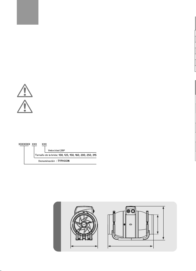
50Hz. They have a motor on ball bearings (rolling bearings). TYPHOON fan is available in seven standard sizes, depending
on the installation diameter of the casing. Fan designation, their appearance, overall and mounting dimensions are shown in
Figure 1 and Table 1.
TYPHOON main dimensional characteristics
Example of designation:
TYPHOON 100 2SP
C
D
B A
Figure 1
Model Speed Voltage /
Frequency
Power
(W)
Speed
(RPM)
Performance
(m3/h)
Air
pressure
(Pa)
Noise
level
(dB)
TYPHOON 100 2SP L2
L1 220~240V/50Hz 25
23
2500
1850
250
180
190
110
40
31
TYPHOON 125 2SP L2
L1 220~240V/50Hz 29
25
2450
1800
355
240
190
110
39
30
TYPHOON 150 2SP L2
L1 220~240V/50Hz 50
42
2600
2000
570
415
305
225
49
40
TYPHOON 160 2SP L2
L1 220~240V/50Hz 50
42
2600
2000
570
415
305
225
49
40
TYPHOON 200 2SP L2
L1 220~240V/50Hz 130
105
2350
1850
1200
1020
380
325
48
46
TYPHOON 250 2SP L2
L1 220~240V/50Hz 225
165
2450
1650
1405
1064
488
371
66
58
TYPHOON 3152SP L2
L1 220~240V/50Hz 390
275
2350
1650
2206
1750
693
435
69
61
Type of current – alternating, single-phase.
Type
Dimensions, m Weight, kg, no more
A B C D
TYPHOON 100 2SP 371 173 216 100 2,3
TYPHOON 125 2SP 291 173 216 125 2,3
TYPHOON 150 2SP 323 190 238 150 3,3
TYPHOON 160 2SP 340 190 238 160 3,3
TYPHOON 200 2SP 400 240 261 200 4,0
TYPHOON 250 2SP 450 290 323 250 7,5
TYPHOON 315 2SP 510 360 410 315 11,5
Installation
TYPHOON fan is suitable for the following types of installation: - on a
wall, a ceiling, or a floor; - for self-assembly or as a part of air ducts;
- for horizontal and vertical installation. For horizontal installation, the
length of the air duct should be at least 0.5m; for vertical installation, a
ventilation hood should be installed to prevent moisture from entering
the device.

EN
9
Axial-flow duct electric fans of the combined type
Purpose
TYPHOON axial-flow duct electric fans are intended for use in ventilation systems of industrial, public, and residential buildings. The duct
funs are connected to round ducts.
Electric fans are designed to remove air and other non-explosive gas-air mixtures that do not contain sticky substances and fibrous
materials, with a dust and other solid impurities content of no more than 10mg/m³, at a temperature of transported air not lower than
-10 °C and above +55 °C
Safety requirements
According to the shock-hazard protection type, the fans refer to Class II devices (for models 100-200), Class I (for models 250-
315), in accordance with GOST 12.2.007.0 -75. The degree of the fan protection against access to hazardous parts and water
ingress is IP44 and the degree of the motor protection is IP44.
ATTENTION!
The fan should not be operated outside the specified temperature range (from -10 °C to +55 °C). It is forbidden to install
the fan in the same ventilation line with the smoke injector pipe from devices with fuel burners
ATTENTION!
• All work on installation and connection of fans should be carried out only with the mains voltage removed.
• The fans shall be connected by electricians who have a special permit for the work performed. Means for disconnecting
from the mains supply should be built into the fixed wiring, in accordance with the installation regulations. The disconnecting
device should disconnect all poles. The grounding conductor should not break.
• The device is not intended for use by persons (including children) with reduced physical, mental capacity, or mental abilities or lack of
experience or knowledge, unless they are supervised or instructed to use the device by a person responsible for their safety. Children should
be supervised to ensure that they do not play with the device.
Model Speed Voltage /
Frequency
Power
(W)
Speed
(RPM)
Performance
(m3/h)
Air
pressure
(Pa)
Noise
level
(dB)
TYPHOON 100 2SP L2
L1 220~240V/50Hz 25
23
2500
1850
250
180
190
110
40
31
TYPHOON 125 2SP L2
L1 220~240V/50Hz 29
25
2450
1800
355
240
190
110
39
30
TYPHOON 150 2SP L2
L1 220~240V/50Hz 50
42
2600
2000
570
415
305
225
49
40
TYPHOON 160 2SP L2
L1 220~240V/50Hz 50
42
2600
2000
570
415
305
225
49
40
TYPHOON 200 2SP L2
L1 220~240V/50Hz 130
105
2350
1850
1200
1020
380
325
48
46
TYPHOON 250 2SP L2
L1 220~240V/50Hz 225
165
2450
1650
1405
1064
488
371
66
58
TYPHOON 3152SP L2
L1 220~240V/50Hz 390
275
2350
1650
2206
1750
693
435
69
61
Type of current – alternating, single-phase.
TYPHOON main specifications
Table 2.
Table 1.
Type
Dimensions, m Weight, kg, no more
A B C D
TYPHOON 100 2SP 371 173 216 100 2,3
TYPHOON 125 2SP 291 173 216 125 2,3
TYPHOON 150 2SP 323 190 238 150 3,3
TYPHOON 160 2SP 340 190 238 160 3,3
TYPHOON 200 2SP 400 240 261 200 4,0
TYPHOON 250 2SP 450 290 323 250 7,5
TYPHOON 315 2SP 510 360 410 315 11,5
TYPHOON fan installation
Installation
TYPHOON fan is suitable for the following types of installation: - on a
wall, a ceiling, or a floor; - for self-assembly or as a part of air ducts;
- for horizontal and vertical installation. For horizontal installation, the
length of the air duct should be at least 0.5m; for vertical installation, a
ventilation hood should be installed to prevent moisture from entering
the device.
In case of non-compliance with these
requirements, the IP44 degree will not
be provided.

EN
10
It is prohibited to install and to use TYPHOON fan with the terminal box
facing down.
The level of inclination of the TYPHOON fan terminal box should not be
lower than the central axis.
1
1. Disconnect power supply.
2. Open the clamp by pulling the tab upwards.
3. Remove the fan casing from the base.
4. Attach the base to the mounting surface and mark the screw hole.
5. Drill holes; fix the fan base to the mounting surface with screws.
6. Install the body by tightly connecting the clamp.
TYPHOON fan installation instructions:
Figure 2aFigure 3a

EN
11
1. Disconnect power supply.
2. Open the clamp by pulling the tab upwards.
3. Remove the fan casing from the base.
4. Attach the base to the mounting surface and mark the screw hole.
5. Drill holes; fix the fan base to the mounting surface with screws.
6. Install the body by tightly connecting the clamp.
ATTENTION!
By installing the speed switch button, the protection level is reduced to IP42.
45
1. Remove the cover with a wide flat screwdriver. To do this, insert a screwdriver into the groove of the plug on the terminal
box casing and knock out the plug with a sharp blow.
2. Install the button in the drilled hole.
3. Connect, according to the diagram using RPI-M(n) 1.5-6.3 connectors (3 pcs., not included). To connect, it is necessary to
bring the wires into flat connectors and clamp them with a crimping tool. You can also connect the contacts in other safe
ways: by twisting, soldering, and welding.
Installation instructions for the speed switch button:
Figure 2.
TYPHOON wiring connection diagram
Wiring connection diagram for models with flange
diameter 100-200 (for fans without speed switch button)
Wiring connection diagram for models with flange
diameter 100-200 (for fans with speed switch button)
Wiring connection diagram for models with flange
diameter 250, 315 (for fans without speed switch button)
Wiring connection diagram for models with flange
diameter 250, 315 (for fans with speed switch button)
Figure 3.
N
(Neutral)
N
(Neutral)
Figure 2aFigure 3a
Figure 2bFigure 3b
N
(Neutral)
N
(Neutral)

EN
12
Maintenance
ATTENTION! The fan and auxiliary control equipment should be isolated from the power supply during
installation and/or maintenance. The equipment should be grounded (for 250, 315 models).
Malfunction Probable cause Troubleshooting method
When connected to the mains, the
fan does not rotate, it does not
respond to controls.
Power supply is not connected.
It was necessary to address a specialist.
Malfunction in the internal connection
Low air consumption. Clogged ventilation system. Clean the ventilation system.
Increased noise or vibration.
Impeller is clogged. Clean the impeller
Fan is not secured or it is incorrectly
mounted. Eliminate the installation error.
Clogged ventilation system. Clean the ventilation system.
Burning odor. The mains wire is connected to L1 and L2. Connect the wires correctly.
Connecting the fan to the mains
The fan has two speeds. Depending on the required fan performance, the phase of the power supply is switched between
the terminals:
For models with flange diameter from 100mm to 315mm
• L1 Low Speed
• L2 High Speed
When setting a high fan speed, depending on the model, it is necessary to connect the fan as follows: L2 (phase of the
supply network), N (neutral of the supply network), protective earth (for models 250, 315).
When setting a low fan speed, it is necessary to switch the phase of the supply network from terminal blocks L2 (phase)
to terminal blocks L1 (phase), connection N (neutral of the supply network), the protective ground remains unchanged (for
models 250, 315).
ATTENTION! In order to avoid damage to the fan, do not simultaneously connect a phase of the supply mains to
terminals L1 and L2.
ATTENTION! All work on installation and connection of fans should be carried out only with the mains voltage
removed.
The fans shall be connected by electricians who have a special permit for the work performed.
Means for disconnecting from the mains supply should be built into the fixed wiring, in accordance with the installation
regulations. The disconnecting device should disconnect all poles. The grounding conductor should not break.
The fan and auxiliary control equipment should be isolated from the power supply during installation and/or maintenance.
The equipment should be grounded (for 250, 315 models).
Please remove the cover from the terminal box, study the wiring diagram (Fig. 2 or Fig. 3), and make the necessary
connections. Check whether a ground connection exists (for 250, 315 models).
After finishing the connection work and checking the connections to the terminal box, move the cover and make sure it is
fixed.
Installation: The length of the firmly installed piping from the fan should be at least 500mm on each side.
When connecting TYPHOON fan with IP44, it is required to pass a network cable with a diameter of at least 4 mm through
a cable gland.
The cable gland is designed for sealed input-output of cables from wires in switchboard enclosures.
The compression nut design has special locking notches to prevent self-loosening. A protective diaphragm
prevents dust from entering the enclosure and achieves a degree of protection IP44 and above.
Maintenance
• Disconnect the fan from the mains;
• Dismantle the fan by disconnecting the middle unit and removing it from the installation site;
• Remove dust from impeller blades using a soft dry brush or cloth;
• Clean the fan impeller blades using a detergent solution;
• Wipe all plastic parts with a soft cloth dampened with soapy water;
• Wipe all surfaces dry;
• Assemble the fan and reinstall;
• Cleaning is recommended every 6 months.

EN
13
Maintenance
ATTENTION! The fan and auxiliary control equipment should be isolated from the power supply during
installation and/or maintenance. The equipment should be grounded (for 250, 315 models).
Malfunction Probable cause Troubleshooting method
When connected to the mains, the
fan does not rotate, it does not
respond to controls.
Power supply is not connected.
It was necessary to address a specialist.
Malfunction in the internal connection
Low air consumption. Clogged ventilation system. Clean the ventilation system.
Increased noise or vibration.
Impeller is clogged. Clean the impeller
Fan is not secured or it is incorrectly
mounted. Eliminate the installation error.
Clogged ventilation system. Clean the ventilation system.
Burning odor. The mains wire is connected to L1 and L2. Connect the wires correctly.
Connecting the fan to the mains
The fan has two speeds. Depending on the required fan performance, the phase of the power supply is switched between
the terminals:
For models with flange diameter from 100mm to 315mm
• L1 Low Speed
• L2 High Speed
When setting a high fan speed, depending on the model, it is necessary to connect the fan as follows: L2 (phase of the
supply network), N (neutral of the supply network), protective earth (for models 250, 315).
When setting a low fan speed, it is necessary to switch the phase of the supply network from terminal blocks L2 (phase)
to terminal blocks L1 (phase), connection N (neutral of the supply network), the protective ground remains unchanged (for
models 250, 315).
ATTENTION! In order to avoid damage to the fan, do not simultaneously connect a phase of the supply mains to
terminals L1 and L2.
ATTENTION! All work on installation and connection of fans should be carried out only with the mains voltage
removed.
The fans shall be connected by electricians who have a special permit for the work performed.
Means for disconnecting from the mains supply should be built into the fixed wiring, in accordance with the installation
regulations. The disconnecting device should disconnect all poles. The grounding conductor should not break.
The fan and auxiliary control equipment should be isolated from the power supply during installation and/or maintenance.
The equipment should be grounded (for 250, 315 models).
Please remove the cover from the terminal box, study the wiring diagram (Fig. 2 or Fig. 3), and make the necessary
connections. Check whether a ground connection exists (for 250, 315 models).
After finishing the connection work and checking the connections to the terminal box, move the cover and make sure it is
fixed.
Installation: The length of the firmly installed piping from the fan should be at least 500mm on each side.
When connecting TYPHOON fan with IP44, it is required to pass a network cable with a diameter of at least 4 mm through
a cable gland.
The cable gland is designed for sealed input-output of cables from wires in switchboard enclosures.
The compression nut design has special locking notches to prevent self-loosening. A protective diaphragm
prevents dust from entering the enclosure and achieves a degree of protection IP44 and above.
Maintenance
• Disconnect the fan from the mains;
• Dismantle the fan by disconnecting the middle unit and removing it from the installation site;
• Remove dust from impeller blades using a soft dry brush or cloth;
• Clean the fan impeller blades using a detergent solution;
• Wipe all plastic parts with a soft cloth dampened with soapy water;
• Wipe all surfaces dry;
• Assemble the fan and reinstall;
• Cleaning is recommended every 6 months.
ATTENTION!
Do not get the cleaning solution on the electric motor!
Water entering the fan is not allowed!
Decommissioning and disposal
At the end of their service life or failure of the fan or its components, they should be disposed of. Disposal shall be carried out
separately, according to material groups: plastic elements, metal fasteners.
ATTENTION!
Dismantling and disassembly of the fan should be carried out by qualified specialists with a complete disconnection
from the power supply.
Service life The established service life is 5 years. At the end of its service life, if the fan has not lost its
functionality, it is used until it fails.
Manufacturer’s warranty
The manufacturer shall guarantee the normal operation of the fan for 3 years (for models 100-160) and 1 year (for models 200-
315) from the date of sale in a retail network, provided that the rules for transportation, storage, installation, operation, and
other requirements of this instruction. In the absence of a mark on the date of sale, the warranty period shall be calculated
from the date of manufacture. In case of malfunctions in the fan operation due to the manufacturer’s fault during the warranty
period, the consumer has the right to replace the fan at the manufacturing plant, provided that the serial numbers on the
product and in the passport match.
The product meets the requirements of
TR CU 004/2011 On the Safety of Low-Voltage Equipment;
TR CU 020/2011 Electromagnetic Compatibility of a Technical Equipment;
TR CU 037/2016 On the Restriction of the Use of Hazardous Substances in Electrical and Electronic Products.
Certificate details:
EAEU Certificate of Conformity No. RU C-RU.АД07.В.01907/20
Valid from September 4, 2020, to September 3, 2025
Series RU No. 0223890
Issued by the product certification body VELES Certification Center, LLC. Address: Nikolsky Lane, building 4, letter A, room 8H,
190068, St. Petersburg, Russian Federation.
Declaration details:
EAEU Declaration of Conformity N RU Д-RU.КА01.В32655/20.
Valid from August 31, 2020, to August 30, 2025
Disposal
This appliance is marked, in accordance with European Directive 2012/19/EU on the disposal of old electrical and electronic
equipment (waste electrical and electronic equipment – WEEE). This Directive defines the EU-wide rules for the collection and
disposal of old appliances.
Storage and transportation rules
It is necessary to store the fan only in the manufacturer’s packaging in a ventilated room at a temperature from -10 °C to +40
°C and a relative humidity of no more than 80% (at T = 25 °C). Shelf life is 2 years from the date of manufacture. Products
shall be transported by any type of transport, provided that consumer or shipping containers are protected from the direct
impact of atmospheric precipitation, from the absence of displacement of transport places during transportation, from the
absence of mutual shocks during transportation and while ensuring the safety of the fans. Transportation shall be carried out,
in accordance with the rules in force for this mode of transport.
Thank you for choosing us!
ES
14
V
Utilización
Los ventiladores de conductos axiales TYPHOON están destinados a ser utilizados en sistemas de ventilación de edificios industriales,
públicos y residenciales. Este tipo de ventiladores están conectados a conductos circulares.
Los ventiladores eléctricos están diseñados para la eliminación de aire y otras mezclas de gas no explosivas que no contienen
sustancias pegajosas y materiales fibrosos, que contienen polvo y otros contaminantes sólidos que no excedan de 10 mg/m3, a una
temperatura del aire transportado no inferior a -10°C y superior a +55°C.
Requisitos de seguridad
Según el tipo de protección contra descargas eléctricas los ventiladores se refieren a la clase II (para los modelos 100 - 200),
clase I (para los modelos 250 – 315) según GOST 12.2.007.0 -75., el grado de protección del ventilador, así como de se motor,
contra el acceso a partes peligrosas y la penetración de agua es IP44.
¡ADVERTENCIA!
Está prohibido hacer funcionar el ventilador fuera del rango de temperatura especificado (de
-10°C a +55°C). Está prohibido instalar el ventilador en la misma línea de ventilación con el conducto de humos de los
aparatos que tienen quemadores de combustible.
¡ADVERTENCIA!
• Todos los trabajos de instalación y conexión de los ventiladores deben realizarse únicamente con la red desconectada.
• Los ventiladores deben ser conectados por electricistas cualificados y autorizados para realizar el trabajo. El dispositivo
de desconexión de la red debe incorporarse al cableado fijo de acuerdo con las normas de instalación. El dispositivo de
desconexión debe desconectar todos los polos. El conductor de puesta a tierra no debe romperse.
• Este aparato no está destinado a ser utilizado por personas (incluidos los niños) con capacidades físicas, sensoriales o mentales reducidas,
o con falta de experiencia y conocimientos, a menos que hayan sido supervisados o instruidos en el uso del aparato por una persona
responsable de su seguridad. Los niños deben ser supervisados para garantizar que no jueguen con el aparato.
Los ventiladores son fabricados por la empresa ERA de acuerdo con las normas y estándares vigentes TU 28.25.20-008-
96059883-2020. Los ventiladores están diseñados para su conexión a la red de corriente alterna con una tensión de
220-240 V y una frecuencia de 50 Hz. Están equipados con un motor accionado por rodamientos de bolas (rodamientos
antifricción). El ventilador TYPHOON está disponible en siete tamaños en función del diámetro de montaje de la carcasa. La
designación de los ventiladores, su aspecto, dimensiones y conexiones se muestran en la imagen 1 y la tabla 1.
Las principales características dimensionales de TYPHOON
Ejemplo de designación:
TYPHOON 100 2SP
C
D
B A
imagen 1
Modelo Velocidad Tensión/
Frecuencia
Potencia
(W)
Velocidad
(RPM)
Rendimiento
cuantitativo
(m3/h)
Presión del
aire
(Pa)
Nivel de
ruido
(dB)
TYPHOON 100 2SP L2
L1 220~240V/50Hz 25
23
2500
1850
250
180
190
110
40
31
TYPHOON 125 2SP L2
L1 220~240V/50Hz 29
25
2450
1800
355
240
190
110
39
30
TYPHOON 150 2SP L2
L1 220~240V/50Hz 50
42
2600
2000
570
415
305
225
49
40
TYPHOON 160 2SP L2
L1 220~240V/50Hz 50
42
2600
2000
570
415
305
225
49
40
TYPHOON 200 2SP L2
L1 220~240V/50Hz 130
105
2350
1850
1200
1020
380
325
48
46
TYPHOON 250 2SP L2
L1 220~240V/50Hz 225
165
2450
1650
1405
1064
488
371
66
58
TYPHOON 3152SP L2
L1 220~240V/50Hz 390
275
2350
1650
2206
1750
693
435
69
61
Tipo de corriente: alterno, monofásico
Tipo
Dimensiones, mm Peso, kg, no más de
A B C D
TYPHOON 100 2SP 371 173 216 100 2,3
TYPHOON 125 2SP 291 173 216 125 2,3
TYPHOON 150 2SP 323 190 238 150 3,3
TYPHOON 160 2SP 340 190 238 160 3,3
TYPHOON 200 2SP 400 240 261 200 4,0
TYPHOON 250 2SP 450 290 323 250 7,5
TYPHOON 315 2SP 510 360 410 315 11,5
Instalación
El ventilador TYPHOON es adecuado para los siguientes tipos de
instalación:
— en la pared, en el techo o en el suelo;
— para instalación separada o en conductos de aire;
— para instalación horizontal o vertical. En caso de instalación
horizontal, la longitud del conducto no debe ser inferior a 0,5 m; en
caso de instalación vertical, debe instalarse un capillo de ventilador
para evitar la entrada de humedad en el aparato.

ES
15
Modelo Velocidad Tensión/
Frecuencia
Potencia
(W)
Velocidad
(RPM)
Rendimiento
cuantitativo
(m3/h)
Presión del
aire
(Pa)
Nivel de
ruido
(dB)
TYPHOON 100 2SP L2
L1 220~240V/50Hz 25
23
2500
1850
250
180
190
110
40
31
TYPHOON 125 2SP L2
L1 220~240V/50Hz 29
25
2450
1800
355
240
190
110
39
30
TYPHOON 150 2SP L2
L1 220~240V/50Hz 50
42
2600
2000
570
415
305
225
49
40
TYPHOON 160 2SP L2
L1 220~240V/50Hz 50
42
2600
2000
570
415
305
225
49
40
TYPHOON 200 2SP L2
L1 220~240V/50Hz 130
105
2350
1850
1200
1020
380
325
48
46
TYPHOON 250 2SP L2
L1 220~240V/50Hz 225
165
2450
1650
1405
1064
488
371
66
58
TYPHOON 3152SP L2
L1 220~240V/50Hz 390
275
2350
1650
2206
1750
693
435
69
61
Tipo de corriente: alterno, monofásico
Las principales características técnicas de TYPHOON
Tabla 2.
Tabla1.
Tipo
Dimensiones, mm Peso, kg, no más de
A B C D
TYPHOON 100 2SP 371 173 216 100 2,3
TYPHOON 125 2SP 291 173 216 125 2,3
TYPHOON 150 2SP 323 190 238 150 3,3
TYPHOON 160 2SP 340 190 238 160 3,3
TYPHOON 200 2SP 400 240 261 200 4,0
TYPHOON 250 2SP 450 290 323 250 7,5
TYPHOON 315 2SP 510 360 410 315 11,5
Instalación del ventilador TYPHOON
Instalación
El ventilador TYPHOON es adecuado para los siguientes tipos de
instalación:
— en la pared, en el techo o en el suelo;
— para instalación separada o en conductos de aire;
— para instalación horizontal o vertical. En caso de instalación
horizontal, la longitud del conducto no debe ser inferior a 0,5 m; en
caso de instalación vertical, debe instalarse un capillo de ventilador
para evitar la entrada de humedad en el aparato.
El incumplimiento de estos requisitos
hará que no se mantenga el grado
IP44.

ES
16
El ventilador TYPHOON no debe montarse ni utilizarse con la caja de
bornes hacia abajo.
El nivel de inclinación de la caja de bornes del ventilador TYPHOON no
debe estar por debajo del eje central.
1
1. Desconecte la fuente de alimentación.
2. Abra el casquillo tirando de la orejeta hacia arriba.
3. Retire la carcasa del ventilador de la base.
4. Coloque la base contra la superficie de montaje y marque el agujero para los tornillos.
5. Taladre los agujeros y fije la base del ventilador a la superficie de montaje con tornillos.
6. Monte la carcasa con el casquillo bien apretado.
Instrucciones para instalar un ventilador TYPHOON:
1. Retire el tapón ciego con un destornillador plano ancho. Para ello, introduzca el destornillador en la ranura del tapón
ciego de la carcasa de la caja de bornes y saque el tapón ciego con un golpe de la mano.
2. Monte el botón en el agujero recién creado.
3. Conecte según el diagrama de cableado con la ayuda de los conectores RPI-M(n) 1.5-6.3 (3 piezas, no incluidas en el kit).
Para conectar, inserte los cables en los conectores planos y utilice las mordazas de presión. También es posible conectar
los contactos por otros métodos seguros: torciendo o soldando.
Instrucciones para instalar el botón de cambio de velocidad:
imagen 2a
imagen 3a

ES
17
1. Desconecte la fuente de alimentación.
2. Abra el casquillo tirando de la orejeta hacia arriba.
3. Retire la carcasa del ventilador de la base.
4. Coloque la base contra la superficie de montaje y marque el agujero para los tornillos.
5. Taladre los agujeros y fije la base del ventilador a la superficie de montaje con tornillos.
6. Monte la carcasa con el casquillo bien apretado.
¡ADVERTENCIA!
El nivel de protección se reduce a IP42 cuando se instala el botón de cambio de velocidad.
45
1. Retire el tapón ciego con un destornillador plano ancho. Para ello, introduzca el destornillador en la ranura del tapón
ciego de la carcasa de la caja de bornes y saque el tapón ciego con un golpe de la mano.
2. Monte el botón en el agujero recién creado.
3. Conecte según el diagrama de cableado con la ayuda de los conectores RPI-M(n) 1.5-6.3 (3 piezas, no incluidas en el kit).
Para conectar, inserte los cables en los conectores planos y utilice las mordazas de presión. También es posible conectar
los contactos por otros métodos seguros: torciendo o soldando.
Instrucciones para instalar el botón de cambio de velocidad:
imagen 2.
Diagrama de cableado de TYPHOON
Diagrama de cableado de para los modelos con diámetro
de brida 100 - 200 (para los ventiladores sin botón de
cambio de velocidad)
Diagrama de cableado de para los modelos con diámetro
de brida 100 - 200 (para los ventiladores con botón de
cambio de velocidad)
Diagrama de cableado de para los modelos con
diámetro de brida 250, 315 (para los ventiladores sin
botón de cambio de velocidad)
Diagrama de cableado de para los modelos con
diámetro de brida 250, 315 (para los ventiladores con
botón de cambio de velocidad)
imagen 3.
imagen 2a
imagen 3a
imagen 2b
imagen 3b
L1
(Low speed / Baja velocidad)
L2
(High speed / Alta velocidad)
white
blanco
black
negro
N
(Neutral)
blue
azul
L1
(Low speed / Baja velocidad)
L2
(High speed / Alta velocidad)
white
blanco
black
negro
N
(Neutral)
blue
azul
amarillo
white
blanco
black
negro
blue
azul
N
(Neutral)
amarillo
white
blanco
black
negro
blue
azul
N
(Neutral)

ES
18
Mantenimiento
¡ADVERTENCIA! El ventilador y el equipo de control auxiliar deben estar aislados de la fuente de
alimentación durante la instalación y/o el mantenimiento. El equipo debe estar conectado a tierra (para
los modelos 250, 315).
Mal funcionamiento Causa probable Solución
El ventilador no gira o no responde
a los controles cuando está
enchufado.
La red eléctrica no está conectada.
Es necesario contactar con un especialista.
Fallo en la conexión interna
Bajo flujo de aire. El sistema de ventilación está bloqueado. Limpie el sistema de ventilación.
Ruido o vibración excesivos.
Засорена крыльчатка. Limpie el impulsor.
Ventilador no fijado o mal montado. Rectificar el error de instalación.
El sistema de ventilación está bloqueado. Limpie el sistema de ventilación.
El olor a quemado. El cable de alimentación se conecta a
L1 y L2. Conecte los cables correctamente.
Conexión del ventilador a la red eléctrica
El ventilador tiene dos velocidades de funcionamiento. En función de la capacidad de ventilador requerida, el cambio de fase
de la red eléctrica se realiza entre los terminales:
Para modelos con diámetros de brida de 100 a 315 mm.
• L1 Low Speed – Baja velocidad
• L2 High Speed – Alta velocidad
Al ajustar la velocidad alta del ventilador, según el modelo, es necesario realizar la conexión del ventilador de la siguiente
manera: L2 (fase de red), N (neutro de red), puesta a tierra de protección (para los modelos 250, 315).
Al ajustar la velocidad baja del ventilador, es necesario cambiar la fase de la red de los terminales L2 (fase) a los terminales
L1 (fase), la conexión N (neutro de la red), la puesta a tierra de protección permanece sin cambios (para los modelos 250,
315).
¡ADVERTENCIA! Para evitar el fallo del ventilador, no conecte la fase de red a los terminales L1 y L2 al mismo
tiempo.
¡ADVERTENCIA! Todos los trabajos de instalación y conexión de los ventiladores deben ser realizados sólo
cuando la tensión de la red esté desconectada.
Todos los trabajos de instalación y conexión de los ventiladores deben realizarse únicamente con la red desconectada.
El dispositivo de desconexión de la red debe incorporarse al cableado fijo de acuerdo con las normas de instalación. El
dispositivo de desconexión debe desconectar todos los polos. El conductor de puesta a tierra no debe romperse.
El ventilador y el equipo de control auxiliar deben estar aislados de la fuente de alimentación durante la instalación y/o el
mantenimiento. El equipo debe estar conectado a tierra (para los modelos 250, 315).
Retire la tapa de la caja de conexiones, revise el diagrama de cableado (imagen 2 o imagen 3) y realice las conexiones
necesarias. Asegúrese de que la puesta de tierra está conectada (para los modelos 250, 315).
Después de completar el trabajo de cableado y comprobar las conexiones con la caja de conexiones, mueva la tapa y
asegúrese de que está bien sujeta.
Instalación: La longitud de la tubería instalada firmemente desde el ventilador debe ser de al menos 500 mm en cada lado.
Al conectar un ventilador TYPHOON con IP44 es necesario pasar el cable de alimentación de al menos 4 mm
de diámetro por un prensaestopas.
El prensaestopas está diseñado para la entrada-salida hermética de los cables de la carcasa de los paneles
de equipo eléctrico.
El diseño de la tuerca del prensaestopas tiene unas muescas especiales de bloqueo que impiden que se
autodesenrosque. Una membrana protectora impide la entrada de polvo en el interior de la cascara y
permite alcanzar un grado de protección IP44 o superior.

ES
19
Mantenimiento
¡ADVERTENCIA! El ventilador y el equipo de control auxiliar deben estar aislados de la fuente de
alimentación durante la instalación y/o el mantenimiento. El equipo debe estar conectado a tierra (para
los modelos 250, 315).
Mal funcionamiento Causa probable Solución
El ventilador no gira o no responde
a los controles cuando está
enchufado.
La red eléctrica no está conectada.
Es necesario contactar con un especialista.
Fallo en la conexión interna
Bajo flujo de aire. El sistema de ventilación está bloqueado. Limpie el sistema de ventilación.
Ruido o vibración excesivos.
Засорена крыльчатка. Limpie el impulsor.
Ventilador no fijado o mal montado. Rectificar el error de instalación.
El sistema de ventilación está bloqueado. Limpie el sistema de ventilación.
El olor a quemado. El cable de alimentación se conecta a
L1 y L2. Conecte los cables correctamente.
Conexión del ventilador a la red eléctrica
El ventilador tiene dos velocidades de funcionamiento. En función de la capacidad de ventilador requerida, el cambio de fase
de la red eléctrica se realiza entre los terminales:
Para modelos con diámetros de brida de 100 a 315 mm.
• L1 Low Speed – Baja velocidad
• L2 High Speed – Alta velocidad
Al ajustar la velocidad alta del ventilador, según el modelo, es necesario realizar la conexión del ventilador de la siguiente
manera: L2 (fase de red), N (neutro de red), puesta a tierra de protección (para los modelos 250, 315).
Al ajustar la velocidad baja del ventilador, es necesario cambiar la fase de la red de los terminales L2 (fase) a los terminales
L1 (fase), la conexión N (neutro de la red), la puesta a tierra de protección permanece sin cambios (para los modelos 250,
315).
¡ADVERTENCIA! Para evitar el fallo del ventilador, no conecte la fase de red a los terminales L1 y L2 al mismo
tiempo.
¡ADVERTENCIA! Todos los trabajos de instalación y conexión de los ventiladores deben ser realizados sólo
cuando la tensión de la red esté desconectada.
Todos los trabajos de instalación y conexión de los ventiladores deben realizarse únicamente con la red desconectada.
El dispositivo de desconexión de la red debe incorporarse al cableado fijo de acuerdo con las normas de instalación. El
dispositivo de desconexión debe desconectar todos los polos. El conductor de puesta a tierra no debe romperse.
El ventilador y el equipo de control auxiliar deben estar aislados de la fuente de alimentación durante la instalación y/o el
mantenimiento. El equipo debe estar conectado a tierra (para los modelos 250, 315).
Retire la tapa de la caja de conexiones, revise el diagrama de cableado (imagen 2 o imagen 3) y realice las conexiones
necesarias. Asegúrese de que la puesta de tierra está conectada (para los modelos 250, 315).
Después de completar el trabajo de cableado y comprobar las conexiones con la caja de conexiones, mueva la tapa y
asegúrese de que está bien sujeta.
Instalación: La longitud de la tubería instalada firmemente desde el ventilador debe ser de al menos 500 mm en cada lado.
Al conectar un ventilador TYPHOON con IP44 es necesario pasar el cable de alimentación de al menos 4 mm
de diámetro por un prensaestopas.
El prensaestopas está diseñado para la entrada-salida hermética de los cables de la carcasa de los paneles
de equipo eléctrico.
El diseño de la tuerca del prensaestopas tiene unas muescas especiales de bloqueo que impiden que se
autodesenrosque. Una membrana protectora impide la entrada de polvo en el interior de la cascara y
permite alcanzar un grado de protección IP44 o superior.
Mantenimiento
• Desconecte el ventilador de la red eléctrica;
• Desmonte el ventilador desconectando la unidad central y sacándola de su lugar de instalación;
• Elimine el polvo de las palas del impulsor con un cepillo o un paño suave y seco;
• Limpie las palas del impulsor con una solución detergente;
• Limpie todas las piezas de plástico con un paño suave humedecido en una solución jabonosa;
• Seque todas las superficies;
• Vuelva a montar y a instalar el ventilador;
• Se recomienda limpiar cada 6 meses.
¡ADVERTENCIA!
No permita que la solución detergente entre en contacto con el motor eléctrico.
No permita que agua entre dentro del ventilador.
Desmantelamiento y reciclaje
Al final de su vida útil o en caso de fallo del ventilador o de sus componentes, los aparatos deben ser reciclados. El reciclaje se
realiza por separado por grupos de materiales: elementos de plástico, elementos de fijación metálicos.
¡ADVERTENCIA!
El desmontaje y el desmantelamiento del ventilador deben ser realizados por personal cualificado y con el ventilador
completamente desconectado de la red eléctrica.
Vida útil La vida útil prescrita es de 5 años. Al final de la vida útil, si el ventilador no ha perdido su capacidad de servicio,
se utiliza hasta que falla.
Garantía del fabricante
El fabricante garantiza el funcionamiento normal del ventilador durante 3 años (para los modelos 100 - 160) y 1 año (para los
modelos 200 - 315) a partir de la fecha de venta en la red de distribución minorista, siempre que se respeten las normas
de transporte, almacenamiento, instalación, funcionamiento y demás requisitos de este manual. Si no hay designación de
la fecha de venta, el período de garantía se calcula a partir de la fecha de fabricación. En caso de mal funcionamiento del
ventilador por culpa del fabricante durante el periodo de garantía, el consumidor tiene derecho a que el fabricante le sustituya
el ventilador siempre que los números de serie del producto y de la ficha técnica coincidan.
Los bienes cumplen
con los requisitos del reglamento técnico de la Unión Aduanera 004/2011 «Sobre la seguridad de los equipos de baja tensión»;
reglamento técnico de la Unión Aduanera 020/2011, «Compatibilidad electromagnética de los dispositivos técnicos»;
reglamento técnico de la Unión Aduanera 037/2016 «Sobre la limitación del uso de sustancias peligrosas en los productos de
equipos eléctricos y electrónicos».
Información sobre el certificado:
Certificado de Conformidad No. EEU RU C-RU.АД07.В.01907/20 Válido desde el 04.09.2020 hasta el 03.09.2025 Serie RU
No. 0223890 Emitido por el Organismo de certificación de productos Centro de Certificación «VELES» SA. Dirección: 190068,
Federación de Rusia, San Petersburgo, calle Nikolsky pereulok, 4, cuerpo A, sala 8H.
Información sobre la declaración:
eclaración de conformidad EEU N RU Д-RU.КА01.В32655/20. Válido desde el 31.08.2020 hasta el 30.08.2025
Disposición
Este aparato está marcado según la Directiva Europea 2012/19/UE sobre residuos de aparatos eléctricos y electrónicos (RAEE).
Esta directiva define las normas de la UE para la recogida y la disposición de los aparatos viejos.
Normas de almacenamiento y transporte
El ventilador debe almacenarse únicamente en el embalaje del fabricante en una habitación ventilada a una temperatura
de -10°С a +40°С y una humedad relativa no superior al 80% (a Т=25°С). Vida útil: 2 años a partir de la fecha de producción.
Los bienes pueden ser transportados por cualquier medio de transporte bajo la condición de proteger la tara de consumidor
o de transporte contra la exposición directa a las precipitaciones atmosféricas, la ausencia de desplazamiento durante el
transporte, la ausencia de golpes mutuos durante el transporte y la garantía de seguridad de los ventiladores. El transporte
se realiza de acuerdo con la normativa vigente para el tipo de transporte en cuestión.
Gracias por habernos elegido.

20
KZ
TYPHOON осьтік желдеткіштері өндірістік, қоғамдық және тұрғын үй ғимараттарының желдету жүйелерінде қолдануға арналған.
Арна желдеткіштері дөңгелек ауа өткізгіштерге қосылады.
Электр желдеткіштері ауаны жоюға және құрамында жабысқақ заттар мен талшықты материалдар жоқ, шаңы мен басқа да
қатты қоспалары 10 мг/м3 аспайтын, ауыспалы ауаның температурасы -10 °С төмен емес және +55 °С жоғары болатын басқа да
жарылыс қаупі жоқ газ-ауа қоспаларын жоюға арналған.
Электр тоғының зақымдануынан қорғау түрі бойынша желдеткіштер МЕМСТ 12.2.007.0-75 бойынша II сыныпты (100 –
200 модельдері үшін), I сыныпты (250 – 315 модельдері үшін) аспаптарға жатады. Желдеткішті қауіпті бөліктерге кіруден
және қозғалтқышының енуінен қорғау дәрежесі - IP44, судың енуінен қорғау дәрежесі – IP44.
!
Желдеткішті көрсетілген температуралық диапазоннан (-10 °С-тан +55 °С-қа дейін) тыс пайдалануға тыйым
салынады. Желдеткішті отын жанарғылары бар құрылғылардан түтін шығаратын құбыры бар бір желдету
магистраліне орнатуға тыйым салынады.
!
• Желдеткіштерді монтаждау және қосу бойынша барлық жұмыстарды тек желі кернеуі алынған кезде жүргізу қажет.
• Желдеткіштерді қосуды орындалатын жұмыстарға арнайы рұқсаты бар электрик-мамандар жүргізеді. Қоректендіру
желісінен ажырату құралдары монтаждау жөніндегі қағидаларға сәйкес стационарлық өткізгішке кіріктірілуі тиіс.
Ажыратқыш құрылғы барлық полюстерді өшіруі керек. Жерге қосу өткізгіші үзілмеуі тиіс.
• Аспап физикалық, психикалық немесе ақыл-ой қабілеттері төмен адамдардың (балаларды қоса алғанда) пайдалануына немесе
олардың тәжірибесі немесе білімі болмаған кезде, егер олар бақылауда болмаса немесе олардың қауіпсіздігіне жауапты адам-
ның аспапты пайдалануы туралы нұсқау берілмеген болса, пайдалануға арналмаған. Аспаппен ойнауды болдырмау үшін балалар
бақылауда болуы тиіс.
Желдеткіштер «ЭРА» компаниясымен ТШ 28.25.20-008-96059883-2020-ға, қолданыстағы нормалар мен стандарттарға
сәйкес шығарады. Желдеткіштер 220-240 V жиіліктегі 50 Hz айнымалы ток желісіне қосылуға арналған. Шарикті мой-
ынтіректерде (жылжымалы мойынтіректерде) қозғалтқышы бар. TYPHOON желдеткіші корпустың орнату диаметріне
байланысты жеті өлшемді шығарылады. Желдеткіштердің белгіленуі, олардың сыртқы түрі, габариттік және қосылатын
өлшемдері 1-суретте және 1-кестеде көрсетілген.
TYPHOON
:
TYPHOON 100 2SP
C
D
B A
1-
-
/
(W)
(
))
(m3/h)
(Pa)
(dB)
TYPHOON 100 2SP L2
L1 220~240V/50Hz 25
23
2500
1850
250
180
190
110
40
31
TYPHOON 125 2SP L2
L1 220~240V/50Hz 29
25
2450
1800
355
240
190
110
39
30
TYPHOON 150 2SP L2
L1 220~240V/50Hz 50
42
2600
2000
570
415
305
225
49
40
TYPHOON 160 2SP L2
L1 220~240V/50Hz 50
42
2600
2000
570
415
305
225
49
40
TYPHOON 200 2SP L2
L1 220~240V/50Hz 130
105
2350
1850
1200
1020
380
325
48
46
TYPHOON 250 2SP L2
L1 220~240V/50Hz 225
165
2450
1650
1405
1064
488
371
66
58
TYPHOON 3152SP L2
L1 220~240V/50Hz 390
275
2350
1650
2206
1750
693
435
69
61
Тоқтың түрі – айнымалы, бірфазалық
TYPHOON желдеткіші келесі монтаждау түрлеріне жарамды:
- қабырғаға, төбеге немесе еденге;
- өздігінен монтаждау үшін немесе ауа каналының бөлігі ретінде;
- көлденең және тік монтаждау үшін. Көлденең монтаждау кезін-
де түтіктің ұзындығы кемінде 0,5 м болуы керек, тік болған кезде
құрылғыға ылғалдың түсуіне жол бермейтін желдету қолшатыры ор-
натылуы керек.
This manual suits for next models
7
Table of contents
Languages:
Other ERA PRO Fan manuals

Popular Fan manuals by other brands


Excelsior
Excelsior Excelair EPF46 instruction manual

Home Decorators Collection
Home Decorators Collection 56006 Use and care guide

Loren Cook
Loren Cook Centri-Vane CV Series Installation, operation and maintenance manual

Hinkley
Hinkley CONCUR 66 instruction manual

Vortice
Vortice PUNTO VORTICE M 90 Instruction booklet

Morris
Morris MTF-16227 user manual