eRapta AYX103 Operating instructions

eRapta HD Wired 10" Backup Camera System
(AYX103)
Installation and Operation Guide

I
PLEASE NOTE:
Before operating this backup system, please read these
instructions completely.
We recommend that you retain this guide with the system as a
ready reference.
If you have any questions, or if you require technical support,
We will respond with 24-hours to provide you with the support
you require.
Please record our email for future refence, if needed.
If you encounter the following:
1. When opened, it is found to be defective or missing parts;
2. You don’t like it when you received;
3. Need technical support and help during the installation process;
4. Camera or monitor gets accident during use;
5. You order a wrong item;
6. Any other after-sales problems that need help.
Please contact us in time, we will provide you with the best service
and technical support, and solve the problems.
This is our contact Email: (24 hours online)

II
TABLE OFCONTENTS
1 WHATS IN THE PACKAGE.........................................................................1
2 SAFETY PRECAUTIONS.............................................................................2
3 SYSTEM DESCRIPTION.............................................................................2
3.1 Monitor.......................................................................................... 2
3.2 Camera...........................................................................................5
3.3 Camera Cable.................................................................................5
3.4 Remote Control..............................................................................6
4 SYSTEM INSTALLATION............................................................................6
4.1 Take the Time to Make an Installation Plan..................................6
4.2 Suggested System Installation Sequence...................................... 7
5 SYSTEM OPERATION............................................................................12
5.1 Read before use......................................................................... 13
5.2 Movie Mode Panel.....................................................................13
5.3 Still Capture Panel......................................................................15
5.4 Clock Settings Panel...................................................................15
5.5 Media Tool Panel....................................................................... 16
5.6 General Settings Panel...............................................................16
5.7 Language................................................................................... 17
6 Troubleshooting..................................................................................18
7 Warranty.............................................................................................20

eRapta
1
1 WHATS IN THE PACKAGE
Congratulations! Our back-up camera system will provide many
years of reliable service, because our monitors, cameras and cables are of
the highest quality. Please examine the shipping box to see if there are
any signs of rough handling. Unpack the box carefully and verify that
each item shows no signs of shipping damage. The image below provides
an overview of all of the items that are part of this system. If any parts
appear damaged or are missing, please contact us at the email address:
1
Meter cable X3
2
2 SAFETY PRECAUTIONS
To operate properly, this back-up system requires the monitor to be
connected to a 9-36 Volt Direct Current power source (Current limited
1~2A). To avoid an electric shock injury or damage to the system, we
recommend that a qualified technician with appropriate training and
experience be obtained to perform this critical connection. A wiring
diagram to make this connection is provided below at paragraph 4.2.2.
3 SYSTEM DESCRIPTION
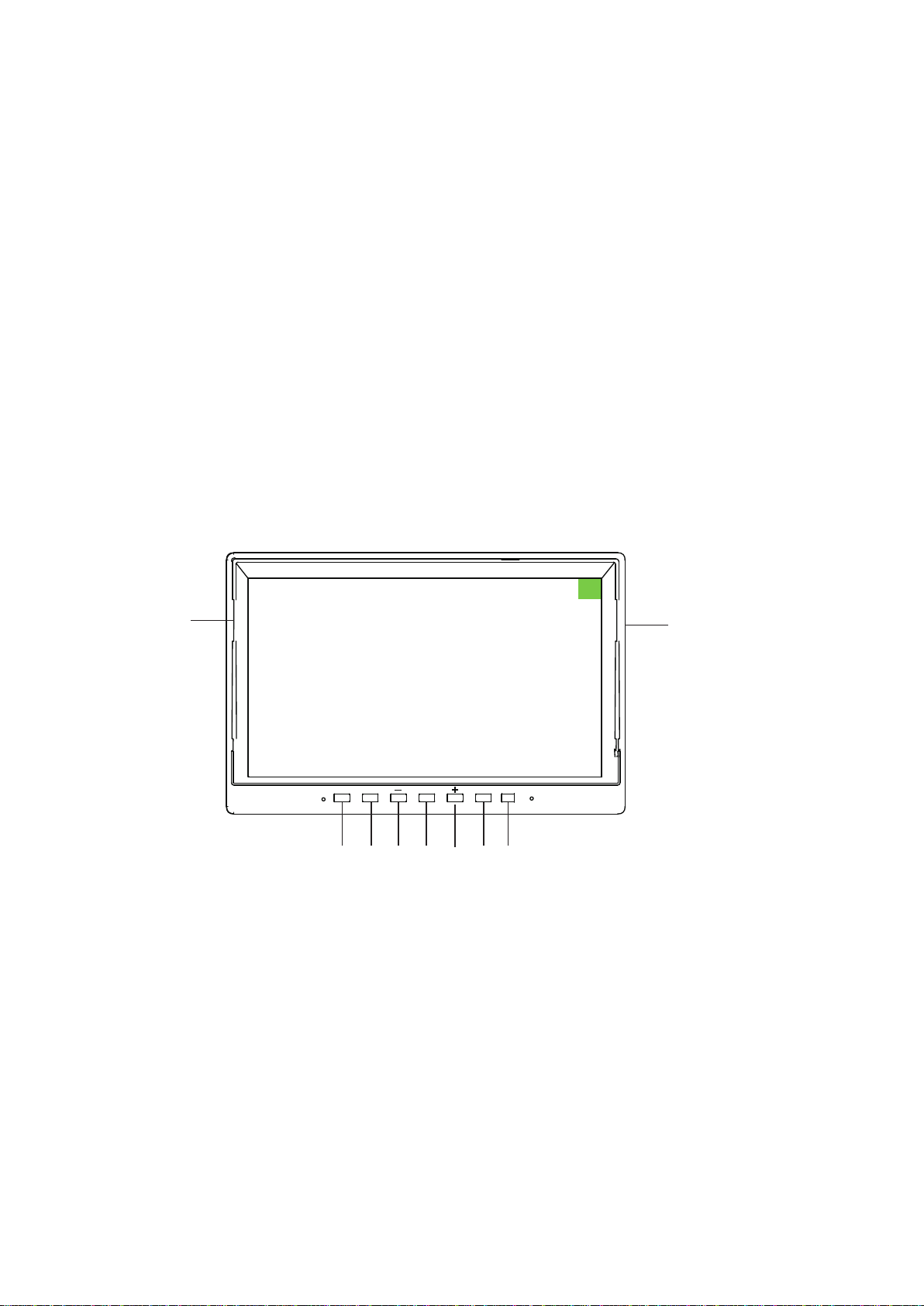
3.1 Monitor
①②
③ ④ ⑤ ⑥ ⑦⑨⑧
MODE V1/V2 M POWER IR
①SD Card Placement
②Sunshade(Unremovable)
③Select/Confirm Button (Start Recording)
④Camera/Channel Switch Button
⑤Function Decrease Button
⑥Menu Button
⑦Function Increase Button
⑧Power ON/OFF Button (power)
⑨Infrared

3
3.1.1 SD Card Access Port
3.1.2 Green Tag
3.1.3 Monitor Bu�ons
An SD card access port is located on the top right side of the monitor.
The SD card is the primary storage device on the monitor, onto which
camera video imagery is captured. You just need to press the memory
card hard and it will pop out or get stuck in. The monitor contains a
32GB SD Card. (Supports 32-128GB SD card.)
There is a protective film on the screen, it is used to remove it. Please
be careful to remove.
(1) MODE : When in menu mode, use to active selection
In the main interface: you can press the MODE button to turn on/off
recording, you can see “·REC ”on the left of the screen (if you have
SD card inside the system). *Recording does not start until press MODE
button.
In the options of menu: you can press it to confirm selection. Such as,
if you want to adjust brightness, you need to: press MENU to enter
menu setting - press + / - button to choose “PICTURE”
option - and then press MODE button to confirm and enter “PICTURE”
option - under “PICTURE” setting, press + / - button to select
the Brightness - if you confirm to adjust the Brightness, please press
MODE button to confirm and then press + / - button to adjust it;
finally press SEL button to confirm and exit this option, and press
+ / - button to select other parameter. (Press MENU button
can return to the previous panel)
(2)V1V2 : Monitor Channel Selection Button

4
As illustrated above, this button allows the user to select various camera
screen displays. Pressing the button repeatedly cycles each camera
channel display one-by-one, and then it will display a two or four camera
channels grouped on the screen(if you turn on a split mode). These
single and multiple display options provide the user with great viewing
flexibility. Before installing the cameras, it is important to decide which
cameras will be paired to which channel numbers so that so that when
the channel selections are made, the screen will display the ideal
grouping of channels. (If you need renumber the cameras, you can
re-pair them, Pairing Method refer to 5.2.1)
* According to the actual situation, you can:
1. Turn on or off a certain camera via CAM-SETUP panel. For example,
(5) : Function Increase Button
No effect on the main interface.
In the menu state, press it to select between these 8 menu options.
In the parameter, press it to increase, for example, if the “Brightness”
control is selected, press this button can increase the brightness of
the screen.
(4) MENU : Monitor System Menu Button
Press this button to enter menu settings.
When under menu/other options’ state, press it can exit and back to
previous panel.
Note: Only in full screen, you can use the MENU button to enter the
menu interface. Please switch the screen to full screen first.
if you choose to close #1, the camera's image will no longer be displayed.
(Path: Menu - CAM-SETUP - Turn ON/OFF the camera.)
2. Turn off or select split screen mode via MODE panel. There are a
variety of split screen modes to choose from, and only supports 2 or 4
cameras display at the same time. (Path: MENU - MODE - Choose split
mode or OFF it.)
(3) : Function Decrease Button
No effect on the main interface.
In the menu state, press it to select between these 8 menu options. In
the parameter, press it to discrease, for example, if the “Brightness”
control is selected, press this button can decrease the brightness of the
screen.
(6) POWER : Power ON/OFF Button
When this button is pressed once the monitor powers-on. The next time
this button is pressed the monitor powers-off.

5
①POWER
Turn on or off monitor
②Video SELECT
Channel switch
③MENU
Enter in menu setting
④MODE SELECT
Start/stop video, take photos,
menu selection
⑤
DOWN-, Reduce when in setting
page
⑥
UP+, Increase when in setting
page
⑤
①
⑥
②
④
3.1.4 Main Screen Interface
(1) Camera 1 : Each display will indicate its CAM# and signal
strength in its upper left.
(2) REC : Recording video, there will be red REC in upper middle
left of display. In the event of SD card issues, re-format the SD card
(RECORD menu).
(3) Rewrite : Shows this sign once you switched on the rewrite
function.
(4) Memory card protection : Try to slide the little yellow
tab if you can’t write data and format on the computer.
(5)If the system does not recognize the memory card, a
prompt will pop up on the right side of the screen: NO
CARD. Please try to reinsert the memory card or format
the memory card.
The system is equipped with a remote control, the remote control is
equipped with electronics, only need to unplug the transparent plastic
sheet at the bottom, you can use it.
3.1.5 Remote Con trol
①POWER Turn on or off monitor
②Video SELECT Channel switch
③MENU Enter in menu setting
④MODE SELECT Start/stop video, take photos,
menu selection
⑤DOWN-, Reduce when in setting
page
⑥UP+, Increase when in setting
page
⑤
①
⑥
②
④
③

6
4 SYSTEM INSTALLATION
The system components are designed to be assembled without difficulty
and with simple tools.
4.1 Take the Time to Make an Installation Plan
We recommend that that you make plan before you begin the installation
of your system components. This approach will eliminate the likelihood
of running into problems with cable routing, camera mount locations and
power supply.
4.2 Suggested System Installation Sequence
Based on our experience, we recommend that you follow this installation
sequence:
Assemble Installation Tools
Install the Monitor
Connect the Power Supply
Connect the Trigger Wire(s)
Install the Cable
Install the Cameras
Connect the Camera Cable to the Monitor
Test and Calibrate the System
Adjust the Camera View
Secure the Camera Cable

7
4.2.1 Install the Monitor
The monitor is delivered with a metal U-shaped bracket and a Fan-shaped
bracket.
U-shaped Bracket Installation:

8
4.2.2 Wiring Schematic Diagram
4.2.3 Power Supply Safety
If you are not confident that you can make the following electrical
connections safely, then please have these connections completed by a
technician.
Before connecting the power supply to the system, please ensure that
voltage of the battery or power source is 9-36 DC Volts.
We recommend that you use shrink wrap electrical connectors in you
wiring circuit so that the insulation on the power wires will not
short-circuit the battery.
4.2.4 Power Supply Connection Options
The monitor is delivered with the system harness plugged into the
monitor socket which can be unplugged if needed to simplify the
mounting or installation of the monitor and camera cables. There are two
options to connect the power to the monitor:

9
Option 1–System is mounted in a Vehicle
Option 2–System is mounted in a Static Location such as a bus
station monitoring system, site security system, etc.
*The green wire only triggers the CH2 camera with Parking Lines. And under
parking mode, other buttons will be locked and can't be used for safety.
4.2.5 Option 1–Vehicle Power Installation
The power supply is normally a storage battery (9-36 Volts).
Connect the Yellow wire to the (+) positive terminal.
Connect the Black wire to the (–) negative terminal.
Connect the Red wire to the vehicle ignition “ACC”switch,
which is the gear switch setting in the ignition that is
immediately before the vehicle’s starter motor switch setting.
With this connection when the vehicle key is turned on, the
monitor will start automatically, and turn-off automatically when
the vehicle key is turned off.
Define which rear view camera will be the back-up camera in
your camera channel (CH) layout. For example, if you have
decided that it will be the CH2 camera to conform to your
preferred CH organization of screens that will be displayed on your
monitor; then connect the Green trigger wire (CH2 trigger) to the
vehicle’s reversing light. This configuration will automatically display
the CH2 camera on the screen whenever the vehicle is in reverse gear.
You can connect the trigger wire according your need, or ignore it.
4.2.6 Option 2–Static Power Installation
Strip the end wires of the Yellow and Red wires.
Twist the end wires together.
Connect Yellow and Red joined wires to the (+) positive
terminal of the power source (9-36V).
Connect Black wire to the (-) negative ground terminal.
Ignore the trigger wire, unless there is a particular useful
application for them in your camera deployment.
Vehicle Installation
Static Installation

10
4.2.7 Install the Camera Cable
Your plan will define the routing of each of the camera cables. When the
cables are being installed, please observe the following procedures:
Use light color tape to label each end of the camera cable to mark its
designated CH number so that there is no confusion when you
connect the cameras and their cables to their respective harness CH
sockets. In addition, mark the end of the short cable attached to each
camera with its designated CH number.
Do not pull aggressively on the connector head of the cable when you
are routing the cables though channels or tight spaces as this may
damage the fine wires in the cable. Use a fish tape to thread the cables
though these areas. Tape the cable securely to the fish tape to
distribute the load when the tape is pulling the cable though the tight
spots.
Install all camera cables so that they cover the distance from the
monitor harness to the position where each camera will be installed.
4.2.8 Install the Camera
Using the appropriate tools install each of the camera in the locations
defined in your layout plan.
The rear-view camera can be installed with screws or bolts using
either the rear mount or ceiling mount units.
Cameras offer the option to drill through the mounting base to pass
the camera cable through in order to have a concealed mount. If this
option is chosen, then you should use sealing compound and/or
rubber grommets to secure the pass-through hole.
The Upgrade Bracket for rear camera included in the package is
optional.
Upgrade Bracket Use the screws to install
Attach it to camera

11
4.2.9 Connect the CameraCables to the Monitor
Please exercise care when you connect the cables together. Both the 8-pin
harness cable and the 4-pin aviation video cables have pins one end that
line up with holes on the other end. In addition, there is an obvious guide
channel that orients to the connectors before they are pushed together.
When all of the cameras are installed, connect the cables for each
camera from the camera to the monitor. Please take care when
aligning the connectors to ensure that the pins are aligned to the holes
before making the connection.
Turn on the monitor.
Cycle the CH- button on the monitor to verify that each of the
cameras is working properly and that all of the screen views or
functioning properly.
4.2.10 Adjust the Camera View
Cycle through the CH- button on the monitor to select a full-screen
view of each camera.
It may be necessary to have a friend assist you to adjust the view of
each camera so that the optimal observation is set for the system.
When the preferred view for each camera is obtained, screw the
retaining screws in snugly.
4.2.11 Calibrate the Monitor Settings
Using the “Menu” button on the monitor, cycle through each of the Menu
options to set the optimal camera brightness, color, contrast, horizontal
position, vertical position, auto, zoom, and language.
4-Pin Aviation Video Cable
Connectors
8-pin connector to Monitor

12
4.2.12 Secure the Cables
When the system is set-up the cables may now be properly secured
and stowed.
Use plastic split-shield cable covers where appropriate to protect the
cables in open areas.
Secure the cables using adhesive 3M type ¼” cable clips and/or zip
ties.
You may have surplus cable length remaining in your installation. If
this is the case, find a convenient place to bundle the cable with zip
ties and securely hide it out of site. We do not recommend shortening
the cable by cutting and rejoining it.
Please note that we offer additional shorter or longer compatible 4-pin
aviation video cables to support the requirements of your installation.
5 SYSTEM OPERATION
The following graphic illustrates the layout of the software management
system (SMS) panels and their associated sub-panels. Please note that
you can press the buttons of monitor or use the remote to access or
modify the SMS panels. While they may appear to be complicated, they
are not.

13
Software Management System Panels and Sub-panels
Logo Main-panels Sub-panels
Movie Mode Movie Quality, Movie Clip Time, Movie Off Time, Auto
Record, Sound Record, To MoviePlayback
Still Capture Still Quality, To PhotoPlayback
Clock Settings Set the Year, Month, Day and Time
Media Tool Format SD-Card
General Settings
Rotate, Car ACC Line, AHD1 Mirror,AHD2 Mirror, Date
Format, Stamp, LCD Power Save, Reset Setup, FW Version,
Contrast, LCD Brightness, Saturation, ColorTemp, VCOM
Language English, Vietnamese, Simplified Chinese,Traditional Chinese
5.1 Read before use
Before enter the MENU setting, please press SEL button to stop
recording firstly.
Press the MENU button of Monitor Or Remote to Enter the
Main-panel.
Under Main-panel, press UP+ /DOWN- button to select the option
from 6 options, and then press SEL button to confirm and enter it.
Press MENU button again to return previous panel.
5.2 Movie Mode Panel
Press SEL button to enter the option, and press UP+ /DOWN- button to
select, and then press SEL button to confirm.
5.2.1 Movie Quality
There are two options for choose: Super Fine, Fine.
5.2.2 Movie Clip Time
This determines the length of each video: Off, 1 min, 2 min, 3 min, 5

14
min, 10 min.
If you choose “Off”, then the system will keep recording a long video
until you stop or power off it.
5.2.3 Movie Off Time
This is the time of the system's flameout recording: 0 min, 5 sec, 30 sec, 1
min, 3 min.
5.2.4 Auto Record
You can choose: On or Off.
If you set it “On”, the system will record automatically when it turns
on (if there is an SD card in the monitor).
5.2.5 Sound Record
Please ignore this function. In order to make our camera more robust and
waterproof, the camera doesn’t have a built-in microphone, so our system
cannot record sound. Thanks for your understanding.
5.2.6 To MoviePlayback
You can switch to the AHD1 video playback panel, press “CH-”
button to switch toAHD2 video playback.
When under theAHD1/2 video playback panel, press UP+ /DOWN-
button to select the video you want to playback, and press SEL button
to confirm.
And press MENU button, it will pop up a window showing options:
Delet, Protect, To PreviewMode. (Delect: delect the videos; Protect:

15
protect the videos; To PreviewMode: the screen can exit it and back
to the main panel.) Press UP+ /DOWN-” button to select and press
SEL button to confirm.
When the video is palying, you can press UP+ /DOWN- button to
speed up the playback speed: 2X, 4X, 8X.
5.3 Still Capture Panel
5.3.1 Still Quality
This means the quality of photo, you can choose: Super Fine, Fine.
5.3.2 To PhotoPlayback
You can switch to the AHD2 photo playback panel, press CH- button
to switch to AHD2 photo playback.
When under theAHD1/2 photo playback panel, press UP+ /DOWN-
button to select the photo you want to see, and press SEL button to
confirm.
And press MENU button, it will pop up a window showing options:
Delet, Protect, To PreviewMode. (Delect: delect the photos; Protect:
protect the photo; To PreviewMode: the screen can exit it and back to
the main panel.) Press UP+ /DOWN- button to select and press
SEL button to confirm.
5.4 Clock Settings Panel
When you enter the “Date Setting” panel, press SEL button to select
the options you want: Year / Month /Day /Hour / Minute / Second /
OK, and then Press UP+ /DOWN- button to change the number.
For example, if you confirm the Year and want to change Month, just
press SEL button to the next.
Finally, choose the “OK” and press the SEL button to save and back

16
to previous panel.
5.5 Media Tool Panel
5.5.1 Format SD-Card
You can format the SD Card with this function. But please careful and
make sure you have saved the important videos to the computer when you
use this.
5.6 General Settings Panel
5.6.1 Rotate
This will rotate the image and the text will also rotate, please careful
to use this function.
If you accidentally use it and flip the screen and text, please select this
option and press the SEL button 6 times, it will return to the original
normal screen.
5.6.2 Car ACC Line
You can turn On/Off the Parking guide line.
Only the CH2 screen will be triggered for full screen with Parking
Lines through Green wire.
Only CH2(BACK) screen can show the Parking guide line.
We recomend you connect the Green wire to the reverse light, then
CH2(BACK) screen can be triggered with parking lines to help you
reversing.
5.6.2 AHD1 Mirror
The AHD1 image can be set Mirrored with this function.
Fox example, if you install theAHD1 camera on the front of your
vehicle, you can mirror it to get the correct image.
5.6.3 AHD2 Mirror
The AHD2 image can be set Mirrored with this function.
Fox example, if you install the AHD2 camera on the front of your
vehicle, you can mirror it to get the correct image.
5.6.4 Date Format

17
There are 4 styles to choose from: None, YYYY MM DD, MM DD
YYYY, DD MM YYYY.
5.6.5 Stamp
There are 4 styles to choose from: Date+Logo, Date, Logo, Off.
5.6.6 LCD Power Save
There are 3 options for choose from: Off, 1 min, 3 min.
If you set the 1 min or 3 min, then the monitor will turn off after 1
min or 3 min if there is no operation.
5.6.7 Reset Setup
Please be careful when you use this feature, it will reset your system.
5.6.8 FW Version
The version information of this system.
5.6.9 Contrast, LCD Brightness, Saturation
You can adjust the screen images’parameters by these options.
Press SEL button to enter the parameter you want to adjust, press
UP+ /DOWN- buttons to increase or discrease, and then press SEL
button to confirm and back to previous panel.
5.6.10 ColorTemp
You can choose the screen color temperature according to your own
habits: Off, Warm Color, Cool Color. It is “Off” by default.
5.6.10 VCOM DC
It can change the brightness of the screen. It is “80” by default.
And we don’t recommend you to change this parameter.
5.7 Language Panel
There are 4 language: English/Vietnamese/Simplified
Chinese/Traditional Chinese, it defaults to English.
You can press UP+ /DOWN- button to choose the language you
want, and then press SEL button to confirm. (Pressing MENU button
can return to previous panel.)
Table of contents
Other eRapta Automobile Accessories manuals


Popular Automobile Accessories manuals by other brands


Camcar
Camcar 40070 Fe Mounting instructions

Alexo Sweden
Alexo Sweden 652-230 Series Installation and operating instructions

Autoenterprise
Autoenterprise Single instruction manual

WIX
WIX WP6806 Installation instruction

Griots Garage
Griots Garage Battery Manager IV manual

Steinhof
Steinhof S-279 user manual