EGR FF935 User manual

FENDER FLARES
INSTALLATION INSTRUCTIONS
COMPONENTS LIST
NO.
1
2
3
4
5
6
7
8
9
10
11
12
13
14
15
16
17
18
19
7
1
1
1
1
1
1
20
12
4
2
4
16
1
4
4
1
1
2
2
Front LHS Fender Flare
Front RHS Fender Flare
Front LHS Bumper Flare
Front RHS Bumper Flare
Rear LHS Fender Flare
Rear RHS Fender Flare
Screw 25mm
Speed Clip 8.5mm hole centre
Speed Clip 11mm hole centre
Phillips Head Screw
Alcohol Wipe
6mm Plastic Scrivet
Rust Inhibitor
10mm Plastic Scrivet
5mm Spacer
Sensor Blanking Molding LHS
Sensor Blanking Molding RHS
Star Washer
Blanking Plate
COMPONENT QTY
NOTES:
• Ensure that both left and right hand Fender Flares suit the profile of the vehicle. Note the areas where the Fender Flares come
in contact with the vehicle.
• Before fitting Fender Flares remove any mouldings, strips or existing flares from the wheel arch. If there is a body side moulding,
mark where the moulding is to be cut, alternatively the Fender Flares can be cut to go around the moulding. Be sure to allow
enough room for the extrusion.
• Read instructions carefully. This product must be installed exactly as specified in these instructions.
Failure to do so may result in improper fit and/or retention.
• Short Phillips head Screwdriver
• Flat head Screwdriver
• Drill & 8mm & 10.5mm Drill Bit
• Steel Ruler
• Tin Snips
• 7mm,8mm & 10mm Socket or Spanner
• Masking Tape
• Mild Soapy Water & Clean Cloths
• Felt Tip Marker
• Utility Knife
Page 1 of 7
FF935
24/05/19
TOOLS REQUIRED:
12
34
56
8 9 10 11
FORD PX3 RANGER 2019MY-
12
13 14 15 16 17 18 19
Rust
Inhibitor
AUTOMOTIVE
SURFACE CLEANER
IMPREGNATED WITH 70% ISOPROPYLALCOHOL
For use in cleaning painted metal,
glass and other vehicle surfaces.
For external use only.
Dispose of properly after use.
LH
RH
FENDER FLARES INSTALLATION INSTRUCTIONS FF935
24/05/19 Page 2 of 7
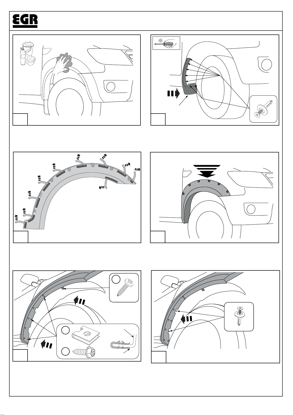
On the inside of the fender flare remove approximately
25mm of the protective liner from the double sided tape
locations. Fold the liner over and secure with masking tape
to the outside of the bumper flare.
Fit the fender flare to the vehicle in the uppermost vertical
position, before final fixings and tape application is com-
pleted as shown.
4
5
MUD FLAP
1 2
Remove the mud flaps by removing the (7) scrivets from
inside the wheel arch as shown.
Wash the areas of contact on the vehicle and wipe dry.
Wipe the fender where the flare will contact, using provided
Alcohol wipes.
3
(x7)
INSTALL
Hold the splash guard inwards and push the supplied (3x) 8.5
Speed Nuts onto the front guard into the 3 hole positions as
shown. Fold the plastic Tab inwards over the fender and secure
with one Phillips head screw.
SPEED NUT
FENDER
7
8
10
+
6
Reattach the wheel arch liner with two factory scrivets.

FENDER FLARES INSTALLATION INSTRUCTIONS FF935
24/05/19 Page 3 of 7
9
11 12
Remove and retain screw and scrivet from the wheel arch
on the front bumper. Remove and retain the Hex head
screw located under the bumper.
x1
x1
x1
Fit the Mud Flap to the Fender Flare aligning with all the
holes. Mark and drill a 10.5mm hole in the liner for the
bottom scrivet as shown.
7
Prepare the Front Mud Flaps by cleaning them & covering
the marked areas with masking tape.
FRONT-LEFT FRONT-RIGHT
FRONT-RHS MUD FLAP
8
Measure and mark Mud Flap area to be removed, as
shown. Using tin snips remove the white area. Repeat for
the LHS Mud Flap. Remove all the masking tape.
REMOVE
MATERIAL
38mm
51mm
10
Fit the Mud Flaps to the Fender Flare and secure with (5)
6mm Plastic Scrivets. Secure the bottom part of the mud flap
with one 10mm Plastic Scrivet and place the 5mm spacer
behind the Mud Flap.
+
10mm
Ø10.5mm 12
14 15
44mm
35mm
3mm
Important FOR VEHICLES
WITH ACTIVE PARK ASSIST
CONTINUE TO STEP 13.
Important FOR ALL OTHER VEHICLES
SKIP TO STEP 17.
FENDER FLARES INSTALLATION INSTRUCTIONS FF935
24/05/19 Page 4 of 7
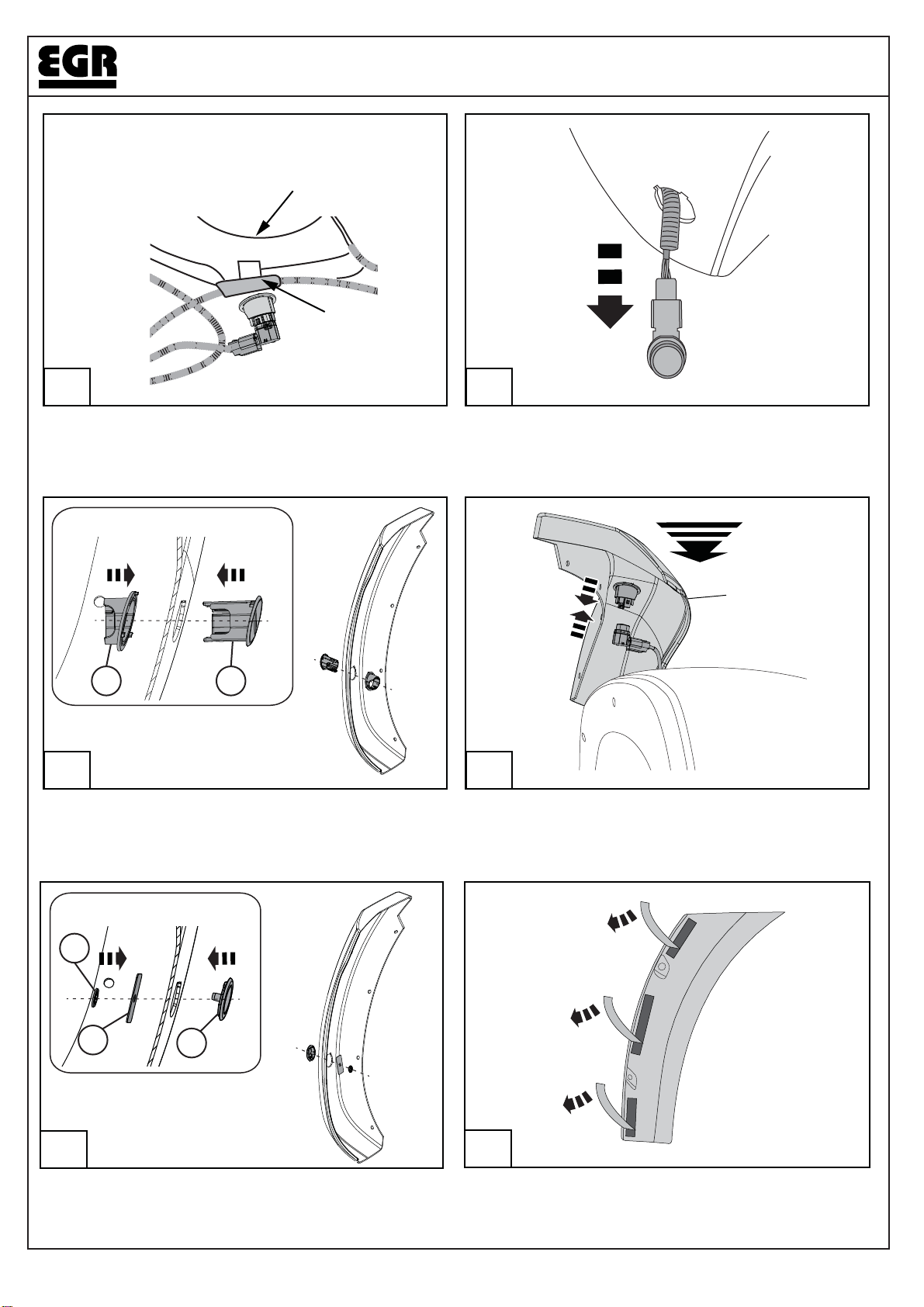
On the inside of the bumper flare remove approximately
25mm of the protective liner from the double sided tape
locations. Fold the liner over and secure with masking tape
to the outside of the fender flare.
18
INSTALL
13
Follow the wiring harness that supports Active park assist
sensor up to the edge clip located under the driving lamp
assembly – dislodge the edge clip from the bumper & leave
off permanently.
14
Pull extra harness length gently through the OEM hole in
the bumper & refit in the Active park assist sensor; leave
loosely ready to fit to the fender flare.
FRONT
QUARTER FLARE
DRIVING LIGHT
HOUSING
DISLODGE CLIP
15
Fit inner (2) & outer (1) escutcheon for the Active park
assist sensor to the fender flare assembly.
16
Hold fender flare assembly close to the bumper & fit Active
park assist sensor to the escutcheon as per the Ford Work-
shop Manual (note the audible ‘click’ when the sensor is
fully home). Skip to step 18.
21
VIEW INSIDE THE FENDER
17
18
19
Fit the sensor cap and retaining strap to the fender flare,
and secure with the starlock washer.
17
SECTION VIEW
SECTION VIEW

Secure the flare using previously removed screw and
scrivet as shown.
Fit the bumper flare to the vehicle as shown.
19 20
21
Ensure that flares are aligned. Remove the tape liner.
Apply firm pressure on the flare to ensure the tape is
contacting the vehicle surface around the full perimeter of
the flares.
FOR THE LHS FRONT FENDER FLARE
INSTALLATION REPEAT STEPS 1 TO 21
FENDER FLARES INSTALLATION INSTRUCTIONS FF935
24/05/19 Page 5 of 7
22 LHS SHOWN
CONTINUE WITH STEP 22 FOR THE REAR
LHS FENDER FLARE INSTALLATION
Wash the areas of contact on the vehicle and wipe dry.
Wipe the fender where the flare will contact, using provided
Alcohol wipes.
x1
x1
x1
On the inside of the fender flare remove approximately
25mm of the protective liner from the double sided tape
locations. Fold the liner over and secure with masking tape
to the outside of the bumper flare.
Fit the fender flare to the vehicle in the uppermost vertical
position, before final fixings and tape application is com-
pleted as shown.
26 LHS SHOWN
LHS SHOWN
27 28
10mmØ8mm
FENDER FLARES INSTALLATION INSTRUCTIONS FF935
24/05/19 Page 6 of 7
23 24
LHS SHOWN LHS SHOWN
MUD FLAP
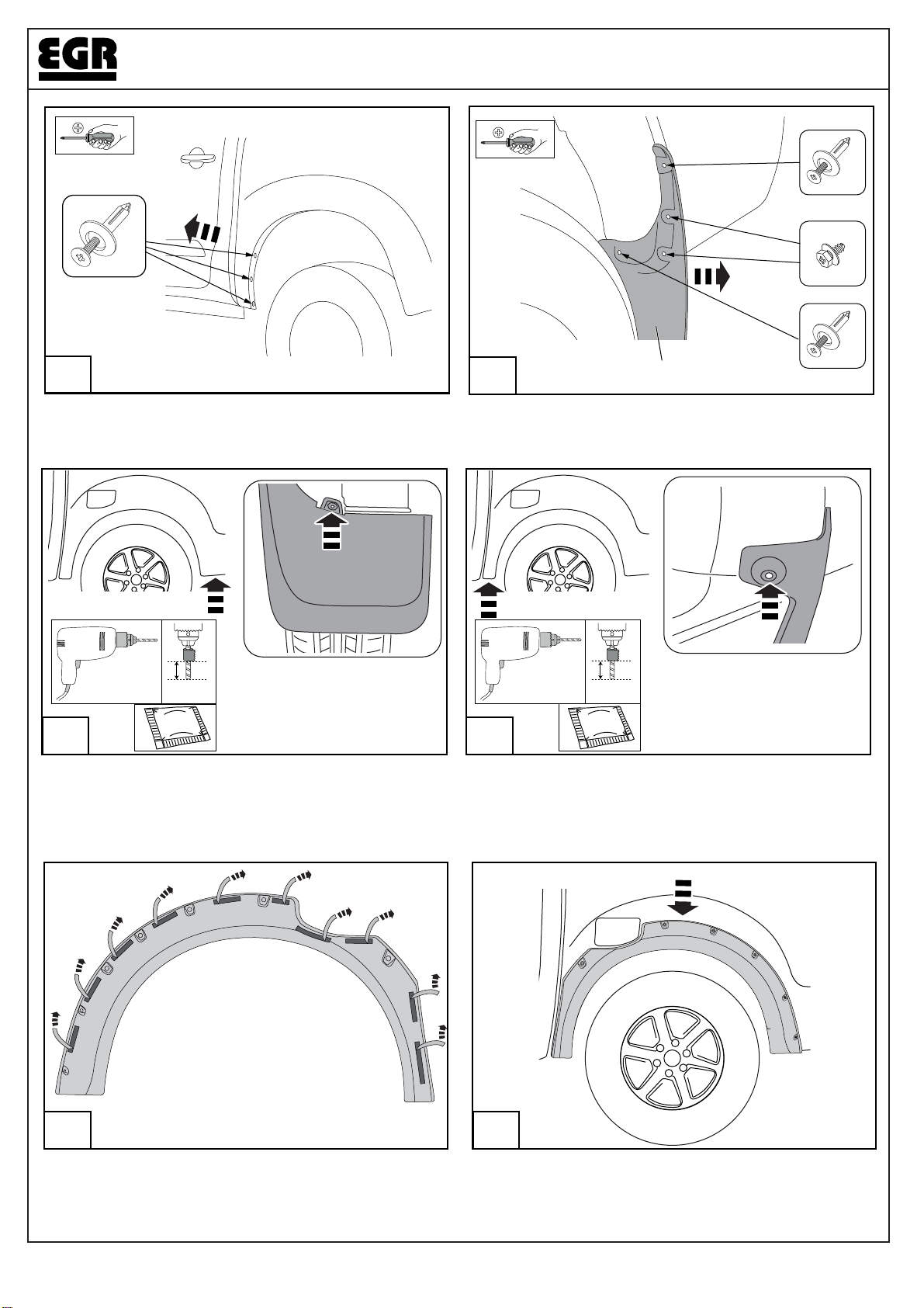
Remove the rear mud flaps by removing and retaining the
(2) screws and (2) scrivets from inside the wheel arch
as shown.
Remove the (3) scrivets from inside the rear wheel arch
as shown.
(x3)
(x1)
(x1)
(x2)
Rust
Inhibitor
25 LHS SHOWN
10mmØ8mm
Carefully drill through centre of rivet holding the liner behind
the rear mud flap, with a Ø8mm drill bit & and 10mm drill
stop as shown. Carefully remove the reminder of the rivet
using needle nose pliers. Apply rust inhibitor to the holes.
Carefully drill through centre of rivet holding the liner with a
Ø8mm drill bit & and 10mm drill stop as shown. Carefully
remove the reminder of the rivet using needle nose pliers.
Apply rust inhibitor to the holes.
Rust
Inhibitor

FENDER FLARES INSTALLATION INSTRUCTIONS FF935
24/05/19 Page 7 of 7
FOR THE RHS REAR FENDER FLARE
INSTALLATION REPEAT STEPS 22 TO 33
Attach the front part of the rear fender flare with (3) Hex
head screws and Speed nuts as per front fender process.
Reuse one factory plastic scrivet as shown.
29 LHS SHOWN
33 LHS SHOWN
31
Ensure that flares are aligned. Remove the tape liner.
Apply firm pressure on the flare to ensure the tape is
contacting the vehicle surface around the full perimeter of
the flares.
+
+
32
Fit the Mud Flap to the Fender Flare and secure with (3)
6mm plastic scrivets and one 10mm scrivet at the bottom,
with one 5mm spacer.
Fit the Mud Flap to the Fender Flare aligning with all the
holes. Mark and drill a 10.5mm hole in the liner for the
bottom scrivet as shown.
10mm
Ø10.5mm
12
7
8
9
x1
Attach the rear part of the rear fender flare with (3) Hex
head screws and factory plastic nuts. Secure the rear lower
part with one hex head screw and Speed nuts as shown.
30 LHS SHOWN
+7
7
79
+
14 15
8
SPEED NUT
FENDER
Table of contents
Other EGR Automobile Accessories manuals


