Erde 213 Parts list manual

58401311-05/06
Coupling lock
MANUFACTURER’S WARRANTY
This trailer is designed to fit B.S.I. / T.U.V approved towing hitches. The manufacturer’s warranty is limited to the repair or replacement
of merchandise which proves defective in materials and/or workmanship, for a period up to one year (6 months for moving parts) after
the purchase date (as shown in sales receipt), provided that the instructions are correctly followed and the product is properly used. If
any article is found to be defective, the purchaser should return it with proof of purchase (sales receipt is proof of purchase and
guarantee starting date), to the place of purchase. Repair or replacement is at the discretion of the manufacturer and no unauthorized
returns will be accepted. If the trailer is found to be defective upon discretion, the manufacturer will repair or replace the trailer at its
discretion, without charge. Freight is not included. This does not affect your statutory rights.
ASSEMBLY AND USAGE INSTRUCTIONS
ERDÉ TRAILERS - Models
!ERDÉ 213
!ERDÉ 233
Accessories avalaible as options
Available for the 233 model only :
Side height
Load bars for ABS
hard top cover
Universal load bars
ABS hard top cover
High trailer cover
With frame 30 cm.
Flat soft cover High trailer cover
with frame 60 cm.
Hydraulic shock
absorber kit
Spare wheel
With or without carrier
Telescopic jockey wheel
Rear stabilising
propstands (pair)
Mesh sides Cover for mesh sides

ASSEMBLY INSTRUCTIONS
FOR ERDÉ TRAILERS MODEL 213-233
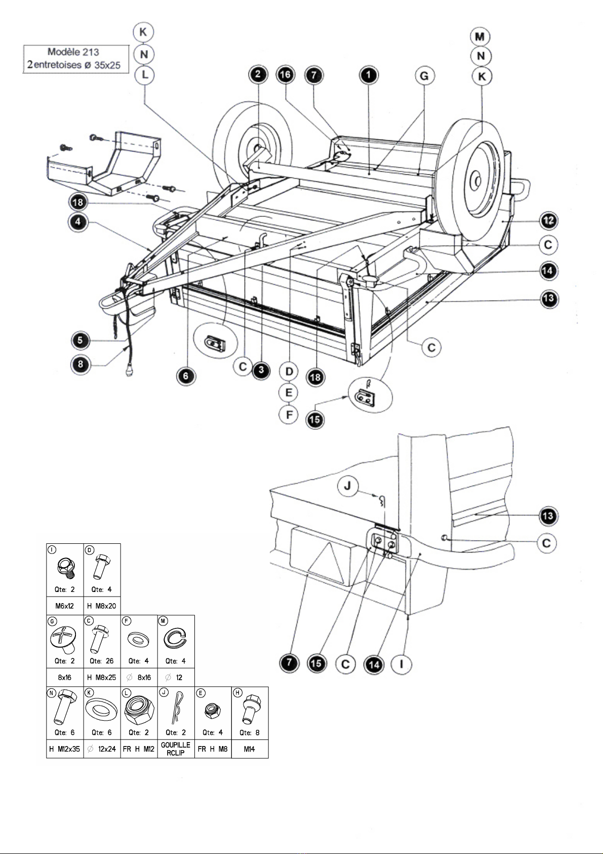
A. ASSEMBLY OF THE CHASSIS
Turn the trailer base panel upside down and place on two trestles or a table and follow
these instructions. DO NOT tighten all the bolts (unless instructed) until all these elements
are assembled (axle, drawbar and lighting board). This ensures that when you finally
tighten all bolts/screws, there is a better fit overall.
1. Fit the tipping hook (3)to the base of the trailer (1). __________________________
2. Mount the axle as per (2). Onto the base of the trailer (1). Hubs facing towards the
back of the trailer (the bolts/non-slip washers/flat washer. screw down onto the nuts
already soldered into position on the axle support reinforcing bars). _________________
3. Assemble the drawbar (partly assembled already)
Unscrew and temporarily take out the bolt HM 10x100 and spread the draw bar arms (4 &
5) and place between the axle supports (2). Screw in place firmly. Rescrew the bolt HM
10x100 and spacer, back in place. _______________________________________
4. Assembly of the lighting board to the base of the chassis (1). Fit the light cluster box
under the central support – Please note the position of the two holes (G) must be
upwards._______________________________________________________________
5. Unroll the lighting cable (8) and fit the yellow and green plugs in their respective
yellow and green connectors on the lighting board. ATTENTION, in connecting the plug
and connector, make sure that the small male lug lines up and fits into the notch of the
female plug.
6. Fit the drawbar A frame support, between the drawbar arms (4 & 5). ____________
Please note : face the flat side with the tipping latch – (already fitted) towards the top of
the A, so that the latch will hook on. Before securing firmly, ensure that the A frame
support, lines up with the base chassis and adjust if required.
TIGHTEN FIRMLY ALL THE BOLTS/SCREWS FITTED SO FAR
7. Line up and Fit the wheels (valves must be on the outside when fitting). __________
Very important, please ensure that you fit the wheel bolts diagonally, tighten to
resistance and once all 4 fitted and when trailer turned over and standing on its
wheels, tighten all the bolts diagonally very firmly and securely (torque 50/55 lbs).
For the following assembly instructions - turn the trailer onto its wheels.
B. ASSEMBLY OF THE SIDE PANELS
1. Fit the two side panels (13) to the trailer base (1). ___________________________
Secure the lighting board base (7) to the side panels (diagram O) using the self tapping
screws (I). _____________________________________________________________
2. Assemble the side bumper protectors (14) and the hinge plates (15) as per diagram
« O ». Both hinge plate pins must face in the same direction. _____________________
ATTENTION : Please ensure you use one hinge plate with hole and one without, for the
front panel fitting and the same for the back panel. The small bumpers fit to the rear half
of the trailer. Attach the front lighting cable on both sides of the front of trailer (18).
3. Fit the front and rear panels, by slipping the panels onto the base hinges and secure
in place using the cotter pin to lock in position. _________________________________
4. Fix the mudguards (12) onto the side panels (13) and to the chassis (1) and tighten all
bolts. _______________________________________________________________
DOUBLE CHECK ALL SCREWS AND BOLTS TO ENSURE ALL ARE TIGHTENED
FULLY. It is important to have the tipping latch firmly in position. Small alterations
in tension are possible by turning the latch ring clockwise or anticlockwise –
always remember to fit the Cotter safety pin, once firmly latched.
VERY IMPORTANT – after short journey towing your trailer, check all the bolts and
ensure none have worked loose – especially the wheel bolts.
SAFETY - Please be safety conscious at ALL TIMES :
* in the trailer assembly
* in towing the trailer
* by regular maintenance checks
* by never exceeding maximum load capacities
* by driving slowly over road humps
PARTS REQUIRED
2 non-slip bolts HM 8x25
4 bolts 12x30
4 non-slip washers 12x24
4 flat washers 12x24
2 spacers 35x25 for model 213 only
2 bolts HM 12x30
2 non-slip washers HM 12
2 flat washers 12x24
3 dome head bolt 8x16
4 bolts HM 8x20
4 non-slip washers
4 flat washers
8 wheel bolts
4 non-slip bolts HM 8x24
2 self tapping screws M 6x12
12 non-slip bolts HM8x25
2 Cotter pins
8 non-slip bolts HMx25
PARTS
REF.
C
N
M
K
N
L
K
G
D
E
F
H
C
I
C
J
C
USE AND MAINTENANCE OF ERDÉ TRAILERS 213/233
These trailers are light duty luggage road trailers and are not suitable for industrial use.
1) COUPLING
On the drawbar: all ERDÉ trailers are equiped with a 50 MM ball coupling with safety
catch, which prevents the trailer becoming detached.
COUPLING AND UNCOUPLING OF TRAILER:
Proceed as follows: lift the end of the handle attaching the coupling to the towball,
operating at the same time the locking trigger on the handle.
Option: It is possible to install an antitheft device that locks the coupling and provides
added security. This is a recommended optional extra.
On the car : towing brackets of a recognised standard should be fitted. Preferably these
should comply with the relevant British and international standards (UL standards AU113
and 114 and international standards ISO1103 and 3553). European standard for towball
is 50 MM diameter. (Tow bars 400 to 600 kgs sufficient for all ERDÉ trailers)
For additionnal security a safety chain is fitted as standard. This should be secured to
the towing bracket at all times, so that in the event of uncoupling the trailer will still be
attached to the towing vehicle. (UK Reg.1995)
2) MAINTENANCE VERY IMPORTANT
Road trailers must be kept in a road-worthy condition and it is a legal requirement that all
trailers be maintained and comply with the different regulations. While there is very little
maintenance required on ERDÉ trailers, it is important that the unit should be checked
annually.
After assembly and the first 60 miles, check the tightness of all nuts/bolts of the following
main parts :* wheels * axle * drawbar
* coupling head * mudguard * lighting
3) HUBS
The wheel hubs including bearing are pregreased for life. No greasing needs to be
done. When necessary, replacement hubs and bearing are available as spares. Do not
put trailer in sea water, damage may occur if hubs/axle immersed in salt water.
4) LOADING VERY IMPORTANT
For your own safety it is important that the trailer is not over loaded. The suspension
units and tyres are designed to carry the following maximum weights.
MAXIMUM LOAD PERMISSABLE
- MODEL ERDÉ 213 310 Kilos
- MODEL ERDÉ 233 305 Kilos
It is an offence to load the trailer to more than its marked gross weight.
The responsability for loading the trailer must be that of the user and as a guide, the
following table will give some typical loads :
QUANTITY/LOAD APPROXIMATE UNIT WEIGHT TOTAL WEIGHT
4 suitcases 25 Kilos 100 Kilos
3 tents 18 Kilos 80 Kilos
6 rucksacks 40 Kilos 240 Kilos
70 logs 3 Kilos 210 Kilos
To obtain good road holding, it is important that the load is loaded with
sufficient weight on the drawbar (5% to 10% of the load). A load on the rear
will cause pitching of the trailer. Once loaded, ensure that the trailer drawbar
is always kept horizontal or slightly on its nose, towards the car. If this is not
the case, change the height of your bracket by using a drop plate which will allow you to
change the height of the coupling.
If fitting a drop plate, refer to drop plate instructions.
Spares can be obtained from Wilstow Ltd 01284-852007
5) TYRE PRESSURE
Inflation pressure should be checked regularly to avoid any risk of abnormal wear and
punctures.
350x8 wheel : 2,5 bar/36 LBS per SQ inch - 480x8 wheel : 2,5 bar/36 LBS per SQ inch
400x10 wheel: 3,5 bar/50 LBS per SQ inch - 500x10 wheel: 3,5 bar/50 LBS per SQ inch
135x13 wheel: 2,5 bar/36 LBS per SQ inch - 145x13 wheel: 2,5 bar/36 LBS per SQ inch
If heavily loaded, or for long trips, it is necessary to increase tyre pressure by 0,50 bars.
Please note : all trailers wheels and tyres fitted to these trailers must be pneumatic and
capable of taking the maximum gross unit weight. They must
be rated to 60 MPH and maintained at the correct tyre pressures. As with
motor vehicles, it is illegal to drive with a mix of radial and crossply tyres on
the same axle. Option: a spare wheel and fixing kit is available and is highly
recommended for safety and convenience.
6) ELECTRICAL CONNECTIONS
The electrical fitments are based on the European standars system equiva-
lent BS 149A.
!Contact Block N° 1 - Left indicator (Yellow or orange wire)
!Contact Block N° 2 - Fog lamp (Blue wire)
!Contact Block N° 3 - Earth (White wire)
!Contact Block N° 4 - Right indicator (Green or violet wire)
!Contact Block N° 5 - Right tail + N° plate lights (Brown wire)
!Contact Block N° 6 - Stop lights (Red wire)
!Contact Block N° 7 - Left tail + N° plate lights (Black wire)
7) REGISTRATION
The number plate of the trailer must be identical to the towing vehicle.
The size of the number plate should be as per BSI standard 520 MM.
Hand written number plates are not acceptable and are illegal.
(Total gross weight of an unbraked trailer includes the weight of the trailer
and the load). It is an offence to load the trailer to more than its marked
gross weight.
TRAILER LAW
The following brief explanation of legislation governing the construction and use of trailer is
given as a guide.
Because legislation and regulation is subject to interpretation, we cannot be held reponsible,
this is not a statement of regulations, only a guide if you are in any doubt you should consult
the DEPT OF TRANSPORT.
THE TRAILER
TOWING WEIGHTS
MGVS (Maximum Gross Vehicle Weight) - WEIGHT OF TRAILER + LOAD.
1 - MGVW of a trailer fitted with over-run brakes 3 500 Kgs
2 - MGVW of an unbraked trailer must not exceed 750 Kgs
or 50% of the kerb weight of the towing vehicle, whichever the lower.
SUSPENSION:All trailers must be fitted with a suspension device on all wheels.
COUPLING : Either a ball (50 MM) or an eye type may be used.
Braked trailers must be fitted with auto-reverse brakes and the coupling must be
hydraulically damped. This is now a requirement but some older trailers may be exempt.
NUMBER PLATE : A rear number plate must be fitted and must be yellow reflecting
with the same registration number as the towing vehicle. The plate and numbers must
conform to BSAU145A. They cannot be hand written.
WHEELS AND TYRES : All trailer wheels and tyres for road use must be pneumatic
and capable of carrying MGVW. They must be rated up to 60 MPH and be maintened at
the correct pressure. As with cars, it is illegal to mix radial and crossply tyres on the
same axle.
MUDGUARDS : Mudgards must be fitted to all wheels, if adequate protection is not
given by the body of the trailer.
DIMENSIONS :
* Max length of 2 or 4 wheel trailers 7 metres
* Max length of 4 wheel trailers 12 metres
(Providing the max gross weight of the towing vehicle exceeds 3500 Kgs)
* Max length of trailer and vehicle 12 metres
* Max width of trailer or vehicle 2,3 metres
* Max width, if towing vehicle MGVW exceeds 3500 Kgs 2,5 metres
BRAKES : When brakes are required on the trailer they must be fitted to all wheels.
LIGHTS AND PROTECTORS : Trailer must be fitted with lights and reflectors. Bulbs
and reflectors must be 'E' or 'e' marked.
MAINTENANCE : it is requirement that all trailers are maintained and used in a
roadworthy condition and comply with the various regulations at all times.
LABELS: the maximum gross trailer weight of an unbraked trailer (up to
750 Kgs MGVW) must be marked on the trailer.
THE TOWING VEHICLE
The maximum gross trailer weight of an unbraked trailer (in the U.K.) is
750 Kgs or 50 PCT of the kerb weight of the towing vehicle.
The maximum gross weight of both braked and unbraked trailers should not however
exceed those stated in your vehicle hand book or the weight rating of your tow bracket.
TOW BRACKET
A towing bracket which conforms to the British standard AU24/1989, should be fitted to
the towing vehicle.
LIGHTING
Trailer lights are generally connected to the towing vehicle by means of a 12N plug and
12S socket. It is recommended that these are wired to BS AU149A.
If the towing vehicle is fitted with rear fog lights, a CUT-OUT is advisable.
A means of audible or visual warning is required to be fitted in the towing
vehicle to detect such failure of indicator lamp.
Care should be taken in stowage of the 12N and 12S plugs when not
connected, to avoid unnecessary damage.
USING THE TOWING VEHICLE AND TRAILER AS A COMBINATION
A trailer being towed by a passenger vehicle or commercial vehicle less that
7,5 tonnes GVW, must conform to the following maximum speeds:
!60 MPH on motorways
!60 MPH on dual carriageways and roads
!50 MPH on other roads
Unless lower speeds are in operation.
A trailer must not be towed in the outside lane of a 3 lane road or motorway
LOADS
It is critical to your safety that trailers are never overloaded beyond their
design capability in such a way as to make it unsafe.
All loads should be evenly distributed and secured.
This manual suits for next models
1
Other Erde Utility Vehicle manuals


