ERGONEERS DIKABLIS User manual

Updated 5/2016

Manual
Dikablis Eye Tracking Glasses Professional
CONTENT
1 General information.........................................................................................................2
2 Dikablis hardware................................................................................................................5
3 First steps..........................................................................................................................10
4 Technical data...................................................................................................................17
5 Warranty and liability claims..............................................................................................20
6 Glossary............................................................................................................................21

Manual
1
Dikablis Eye Tracking Glasses Professional
Dear Customer,
By choosing the Dikablis eye tracking system from Ergoneers, you have opted for innovation,
quality, performance and reliability. Dikablis will provide you with maximum support on all of
your eye tracking experimentation projects and guarantees to offer you the utmost in effi-
ciency and benefits. Ergoneers are providing you with a complete and consistent hardware
and software system for scientific eye tracking. Compatibility problems between hardware
components or limitations in terms of internal data flow are therefore a thing of the past.
Dikablis is used to capture and analyze the direction of your test subject's gazes, as well as
the movements of their eyes and heads, in experimental situations. The integration of the key
system components into the head unit means that the system offers unrestricted freedom of
movement. The live view integrated into the recording software means that the viewing be-
havior of test subjects who are able to move around the room freely can be recorded and
monitored simultaneously on the screen.
The list of potential uses for Dikablis is endless, ranging from the assessment of design and
structural objects to the behavior-optimized design of user interfaces or for eye behavior as-
sessment in safety-critical situations. The degree of experience in the field of eye tracking is
irrelevant for the user, since beginners as well as experts are able to harness the system's
potential with equal effectiveness.
The supplied package includes D-Lab Essential, the basic version of the measurement and
analysis software, which allows the results of your experiments to be processed intuitively
and in a straightforward manner. This standard software allows you to edit your empirical da-
ta manually. Ergoneers also offer the option of multiple expansion modules for D-Lab, such
as modules for automatic analysis and preparation of the data obtained. With D-Lab,
the manual processing of data becomes redundant and you have the option of high-quality
graphics and informatively-presented representations of the measured eye behavior.
Our product portfolio currently comprises the two versions Dikablis Eye Tracking Glasses
Professional Cable and Dikablis Eye Tracking Glasses Professional Wireless . Which of
these two versions you choose depends greatly on where your applications will be used.
This manual provides a detailed description of your system's hardware. The fundamental
steps of assembly are explained and illustrated with graphics.
We are delighted that you have chosen a product from Ergoneers, and we very much hope
you enjoy using the Dikablis eye tracking system.
Your Ergoneers team

Manual
2
Dikablis Eye Tracking Glasses Professional
1 GENERAL INFORMATION
Safety information
Read these instructions for use carefully before connecting and commissioning the
system! As with all technical systems, flawless function and operating safety can only
be guaranteed if the usual safety precautions are taken during operation and the spe-
cific safety information contained in this manual is complied with.
Note
The following information must be noted in order to reduce the risk of fire or electric shock.
Failure to do so can result in death or serious injury.
1. The mains plug must not be connected or disconnected from a socket with wet hands. Do
not use the power packs in damp environments (e.g. bathroom).
2. The power packs must not be exposed to direct sunlight.
3. Dikablis must not be used if the mains cable or power pack are damaged.
4. The plugs on the power pack must never be connected with force.
5. To avoid damaging them, the system components must be handled with care and must
not be dropped.
6. The housings do not contain any parts that can be maintained by the user. The device
housing must only be opened and repairs carried out by an Ergoneers employee.
7. Before commissioning the system, ensure that the mains voltage specified on the type
plate of the individual components matches the mains voltage being supplied. An incor-
rect mains voltage can destroy the device.
8. The system must only be operating with original Ergoneers accessories or Ergoneers-
approved accessories. No liability is accepted for damage caused by the use of unap-
proved accessories or third-party components.
9. If modifications are made without the written consent of Ergoneers, the warranty and EU
declaration of conformity issued shall be rendered null and void.
Explanation of the symbols used in this manual:
General caution
Caution, hazardous electrical voltage: Danger of electric shock!
Caution, hot surface!
Information: Read the information carefully
Note: Failure to observe this information can damage or destroy your device or
impair its performance

Manual
3
Dikablis Eye Tracking Glasses Professional
FAQs
Detailed documentation of all of the questions that have arisen so far and their associated
answers can be found online at www.ergoneers.com/faq.
If you have any questions for which you cannot find an answer, please send an e-mail to
Supplied package
1.3.1 Dikablis Cable
Figure 1 - Cable supplied package
The following parts are included in your Dikablis Cable eye tracking system:
Head unit
Connector box incl. power pack
USB 3.0 cable (3 meters)
Licensing dongle incl. software
Two attachable lenses for the scene camera

Manual
4
Dikablis Eye Tracking Glasses Professional
1.3.2 Dikablis Wireless
Figure 2 - Wireless supplied package
The Dikablis Wireless eye tracking system contains all of the components of the Cable
system and also the following parts:
Rechargeable batteries (at least one; optionally a second one)
Backpack for transporting the transmitter unit
Router
Microsoft Surface Pro Tablet with pre-installed D-Lab Mini
Associated power packs
1.3.3 Optional upgrades
It is possible to upgrade from Dikablis Cable to Dikablis Wireless at any time. To do this,
simply acquire the digital radio path (comprising a router and tablet).
Dikablis Wireless, just like Dikablis Cable, can be used with cables by linking the Dikablis
system directly to the recording computer, i.e. without a tablet or router.
1.3.4 Software
The supplied package includes a USB licensing dongle on which the installation files for
D-Lab Essential are located. The installation and commissioning of the software are de-
scribed in point 3.1.3. If you have purchased a notebook from Ergoneers along with the
eye tracking system, the D-Lab software is already pre-installed on it.

Manual
5
Dikablis Eye Tracking Glasses Professional
2 DIKABLIS HARDWARE
This section explains the eye tracking system's hardware components. First, the version-
neutral system parts such as the head unit and recording computer are described. This is
then followed by a version-specific description of the components for Dikablis Cable and
Dikablis Wireless.
When establishing plug connections, please always check the compatibility of the plugs be-
ing used. The connections involved represent complex plug connections that can be dam-
aged by the use of external force. If you feel strong resistance while trying to establish or re-
lease a plug connection, please check that the plugs and connecting elements are a match
for each other.
Each plug has a different number of pins and therefore only fits into one specific jack. Red
markings on the power plug and the associated jack make connecting these easier. Ensure
that the markings overlap, as shown in Figure 3. Please ensure that the plug and jack
match before connecting the plug!
If the plug is connected incorrectly, damage to the jack and/or plug can
result.
Before connecting a plug, check that the number of pins on the
plug matches the pattern of the jack.
When connecting the USB 3.0 plug, ensure that you only screw
in the plug once it has been properly inserted.
To release the plug, grasp it by the fluted section and pull it out.
Never pull the plug out by the cable!
The connector box is permanently attached to the head unit.
Any attempt to remove the cable can damage the eyewear!
Figure 3 - Overlap of the markings

Manual
6
Dikablis Eye Tracking Glasses Professional
Head unit
One system-neutral component of your Dikablis system is the head unit, which is shown in
Figure 4. It has an identical structure for all system versions, however the connection to the
recording computer varies: either a direct cable connection is used or a wireless one is es-
tablished via the Microsoft Surface tablet and the router. The head unit itself is made from
resilient titanium.
Figure 4 - Head unit
The functions of the individual parts of the head unit, as shown in Figure 4, are explained be-
low:
The eye cameras are linked to the frame of the head unit via a mobile swan neck and
are aligned with the wearer's eyes. The camera records a black/white video of the
eye with a resolution of 640 x 480 pixels and up to 60 frames per second.
The field camera records a high-resolution, color video of the surroundings that are
observed in the test subject's field of vision during the recording. The resolution in this
case is 1920 x 1080 pixels at 30 frames per second. To adjust the image of the field
camera to the test subject's field of vision, the field camera can be realigned vertical-
ly. Magnetic clip-on lenses can also be used to adjust the field of vision between 40°
and 90°.
The nose piece, the brow rest, the side arms and the elastic strap ensures a secure
and comfortable position for the head unit on the test subject's head.
The connecting cable to the cable box or transmitter provides the power supply to the
electrical components of the head unit and ensures the flow of data to the relevant
system components.
Scene Camera
Eye Camera

Manual
7
Dikablis Eye Tracking Glasses Professional
The infrared LED allows adequate illumination of the eye area.
If someone wearing the head unit (test subject) impacts with another
object (e.g. car airbag, fall), they may sustain injuries.
Avoid dangerous situations
Notify the test subject of this potential danger and ask him or
her to pay particular attention to safety issues. Ensure that the
test subject has understood this and agrees.
Recording computer
One important element of the eye tracking system is the recording computer. Whatever the
design of your Dikablis system, the recording computer represents the central entity for re-
cording and processing the eye tracking data. The software required to capture the data is
supplied on the licensing dongle. If the recording laptop was purchased from Ergoneers, the
software is already pre-installed.
Please note that no other additional programs or data may be installed on the recording lap-
top. The laptop is designed for real-time eye tracking. The installation of additional software
may mean that this function can no longer operate correctly.
The recording computer must satisfy the performance requirements
specified for the operation of Dikablis and D-Lab. Ergoneers recom-
mend using a Dell Precision M4800 or equivalent computer. Minimum
recommendations:
CPU: Intel™ Core i7
RAM: 8GB 1600MHz DDR3
Graphics: Nvidia Quadro K2100M 2GB GDDR3
Hard drive: 2.5 inch SATA 750 GB @ 7200 RPM
OS: Windows 7 Professional 64 Bit
Only the Dell Precision M4800 has been tested by Ergoneers and ap-
proved for operation with D-Lab. As a result, we are only able to guar-
antee smooth operation of the software with this computer. It can be
ordered as an option with the Dikablis system from Ergoneers.
Dikablis Cable
2.3.1 Connector box
The connector box contains some of the electronics required for Dikablis Cable and is shown
along with the power pack which supplies current in Figure 5. Figure 6 then shows a detailed
frontal view of the connector box. The connections are labeled according to their function and
explained below.

Manual
8
Dikablis Eye Tracking Glasses Professional
Figure 5 - Connector box with power pack
Status LED
USB 3.0 port
Power connection
Figure 6 - Connector box
When establishing plug connections, please always check the compatibility of the plugs be-
ing used. The connections involved represent complex plug connections that can easily be
damaged by the use of external force. If you feel strong resistance while trying to establish or
USB 3.0 Socket
Status LED
Electrical connection

Manual
9
Dikablis Eye Tracking Glasses Professional
release a plug connection, please recheck that the plugs and connecting elements are a
match for each other. All plugs are designed so that there is only one jack into which they fit.
The red markings on the plug and jack make connecting them easier; ensure that the mark-
ings overlap.
Dikablis Wireless
In addition to the head unit and the connector box described in 2.3, the Wireless system also
includes a number of other components.
2.4.1 Router
The WLAN router included in the supplied package is used to transfer the live image cap-
tured by Dikablis to a remote recording or monitoring computer.
Optionally, it can also act as an access point if it is equipped with a LAN cable. The router
can establish a fast 5 GHz network and a normal network for older computers.
2.4.2 Tablet
The data from the Dikablis eyewear is recorded by a Microsoft Surface Pro 3 tablet and the
live image is transferred simultaneously via WLAN to the remote computer. Once the eye
tracking study is complete, the highly accurate data stored on the tablet can be transferred
via WLAN to the analysis computer.
2.4.3 Rechargeable Battery
To operate the tablet and connector box independently of a fixed power source, the Dikablis
Wireless system comes with a rechargeable battery that allows Dikablis to be used on the
move. The battery supplied is intended for the operation of the Dikablis eyewear. An optional
further battery can be purchased from Ergoneers to prolong the tablet's internal battery. One
battery charge with Dikablis allows uninterrupted use of the system for around 2 hours.
2.4.4 Backpack
The backpack included has been created to directly address the needs of Dikablis Wireless
users. The inlay is designed so that all equipment is held securely in place inside the back-
pack. The inlay also features a cable management system that ensures the secure position
of plug connections.

Manual
10
Dikablis Eye Tracking Glasses Professional
3 FIRST STEPS
Commissioning
3.1.1 Dikablis Cable
The complete setup of Dikablis Eye Tracking Glasses Professional Cable with all of the com-
ponents included in the supplied package can be seen in Figure 7. The system is cable-
linked and can therefore only be used within a radius of 3 m from the recording computer.
Ergoneers also offer a 5 m cable which can be purchased as an optional alternative. Dikablis
Cable is particularly appealing for applications in which the separate handling of the head
unit and recording computer is of secondary importance, such as in a fixed-location driving
simulator or for use in a usability laboratory.
To commission your Dikablis Cable eye tracking system, proceed as follows:
Set up the parts of the eye tracking system as shown in Figure 7.
Start the recording computer and connect the licensing dongle to a USB port. Wait
around 1 minute until the hardware components on the recording computer have ini-
tialized.
Start the recording software via the D-Lab icon, which can be found on the desktop of
the recording computer.
The D-Lab interface opens. Configure the eye camera as described in the D-Lab in-
structions.
The eye tracking system is now ready for use. To record eye data, follow the instructions in
the D-Lab manual.
Figure 7 - Flowchart for Cable
Link the
connector
box to the
PC via
USB
Supply power to
the connector box

Manual
11
Dikablis Eye Tracking Glasses Professional
3.1.2 Dikablis Wireless
The structure of the Dikablis Wireless system is shown in Figure 8. A special inlay has been
provided to secure components in place in the backpack. The use of this inlay is described in
the Dikablis Wireless Quickstart Guide. To use the Wireless system, however, other settings
must be made to the software and hardware. Once these settings have been made, the
Wireless system has a range of around 50 meters in open spaces, making it ideal for motion
and outdoor studies.
To set up the system, proceed as follows:
Connect the router to the power supply and switch it on. Now wait a few seconds until
the router is ready for operation. This is indicated by the Power LED lighting up
green.
Now open the network settings of your Surface tablet and connect to the router's
WLAN network (Dikablis-Wireless-XXXX-5GHz). Authentication is performed by
pressing the WPS button on the reverse of the router or manually by entering the
password which can also be found on the reverse.
Repeat these steps on your recording computer and connect to the network. If you
are using an older computer which does not support 5 GHz networks, use the other
network available (Dikablis-Wireless-XXXX) on both devices (laptop and Surface).
Now launch the D-Lab Mini App on your tablet. Once it starts, the program displays
the status message "Awaiting connection".
Now launch D-Lab on your recording computer. D-Lab detects the Surface tablet and
the status message on the tablet changes to "Connected".
You can now use the Dikablis Wireless system. To be able to process analysis data after re-
cording it on the recording computer, right-click on the session and download the data. You
will find more information in the D-Lab manual.
Figure 8 - Flowchart for Wireless
For more information about the backpack inlay, see the Dikablis Wireless Quickstart Guide.
Supply
power to
the con-
nector box
Link the con-
nector box to
the PC via
USB
Supply
power to
the router

Manual
12
Dikablis Eye Tracking Glasses Professional
3.1.3 Software installation
Please note that you will need local administrator rights on the computer on which you plan
to install the software. To install one or more of the three Dikablis applications, proceed as
follows:
Connect the licensing dongle to a free USB port on your computer.
Launch Setup, which can be found on the licensing dongle or which can be obtained
from an Ergoneers employee.
Press "Install" to start the installation process. Confirm the prompts. D-Lab is installed
and shortcuts to it are created on the desktop. An Ergoneers Dikablis directory with
shortcuts to the installed applications is added to the computer's Start menu.
Please note that the applications must be installed for each user who wishes to work with
them.
Figure 9 - D-Lab installation

Manual
13
Dikablis Eye Tracking Glasses Professional
3.1.4 Eyewear positioning and calibration
To ensure that your experiments work as well as possible, it is important to secure the head
unit properly to the test subject's head and to set the cameras' recording range correctly. To
adjust the cameras, however, the recording computer must be switched on and D-Lab must
be running.
To ensure the best possible fit of the head unit on the test subject's head, be aware of the fol-
lowing:
1. To attach the head unit correctly, hold the elastic head strap with one hand and the
brow rest with the other. Position the nose rest like a normal spectacle frame on the
top of the test subject's nose and pull the elastic head strap over the head so that the
forehead rest lies on the forehead. The figure below shows an example of a correctly
fitted head unit.
2. Secure the head strap, adjusting the elastic head strap to the required length by
pushing and moving the push button. The equipment must not be uncomfortably tight
or pinch at any point. The ergonomic design of the head unit improves comfort for the
wearer and ensures that experiments can be carried out without hindrance and with
greater comfort.
Figure 10
Figure 11
Comment: Dikablis can also be used by spectacle and contact lens wearers. Spectacle
wearers should place the head unit over their spectacles, as shown in Figure 11.
Open D-Lab and create a new study. Now open a new visualization and drag the eye tracker
to the visualization window as described in the D-Lab manual. The eye camera must be ad-
justed so that the eye is in the middle of the image, as horizontal as possible and in focus.
The eye camera is attached to a flexible swan neck cable. This type of fastening allows easy
adjustment of the camera in front of the eye. The position of the eye camera can be adjusted
horizontally and vertically and its orientation changes (cf. figure below).
The text below describes the steps required to achieve the best possible settings of the eye
camera. Starting from a completely incorrect setting, the example will show how this can be
changed in stages until the result shown in Figure10 is achieved.

Manual
14
Dikablis Eye Tracking Glasses Professional
Figure 12 - Positioning in front of the eye
Starting out
The starting position is shown in the figure below. The settings contain the following errors:
Camera too close to the eye
Eye skewed in the image
Camera too far to the side
Eye too far up
Setting the distance between the eye camera and the eye
You can set the distance between the eye and the eye camera by moving the eye camera
towards or away from the eye. You will know when you have reached the correct distance by
the fact that the eye camera image comes into focus, as shown.

Manual
15
Dikablis Eye Tracking Glasses Professional
Setting the angle of the eye within the eye camera image
As show on the left, the eye is skewed in the eye camera image. This can be rectified by ro-
tating the eye camera to the correct position. The figure on the right shows the correct setting
in which the eye lies horizontally in the image.
Setting the horizontal position of the eye within the eye camera image
As can be seen on the left, the eye is pushed very much to the right in the eye camera image
and therefore the camera is unable to permanently record it. Move the camera to the right or
left in front of the eye to adjust the horizontal position of the eye in the eye camera image.
The figure on the right shows the horizontal position after successful adjustment.
Setting the vertical position of the eye within the eye camera image
The final step of the adjustment process is the correct vertical setting of the eye in the eye
camera image. To do this, move the camera upwards or downwards in front of the eye. As
the figure on the left shows, the eye is positioned too far up in the eye camera image. Tilting
the eye camera downwards slightly allows the correct vertical setting to be achieved, as
shown on the right.

Manual
16
Dikablis Eye Tracking Glasses Professional
Position of the eye camera in front of the eye
The swan neck allows the vertical position of the eye camera in front of the eye to be
changed across a suitably large area. The following illustration shows a correctly aligned
camera.
If the test subject has long eyelashes which partially cover the pupil when the eye is being
filmed directly from the front, it is recommended that the eye be filmed more from below,
since the camera can then film underneath and past the eyelashes. To reduce the effect of
the eyelashes on pupil detection, the masking options in the pupil detection settings can also
be used.
Figure 13 - Correctly aligned eyewear
The scene camera looks forward and "sees" what the test subject sees. Open D-Lab and
drag the eye tracker into a visualization window. Now examine the represented area of the
scene camera in the preview window. If the surroundings being investigated are not shown
as desired, you will need to adjust the field camera accordingly. To do this, apply gentle
pressure to the scene camera and align it either upwards or downwards. Ensure that the test
subject assumes the same position that he would for the experiment.
Manual
17
Dikablis Eye Tracking Glasses Professional
4 TECHNICAL DATA
The following tables show the technical data for the various components in the Dikablis sys-
tem
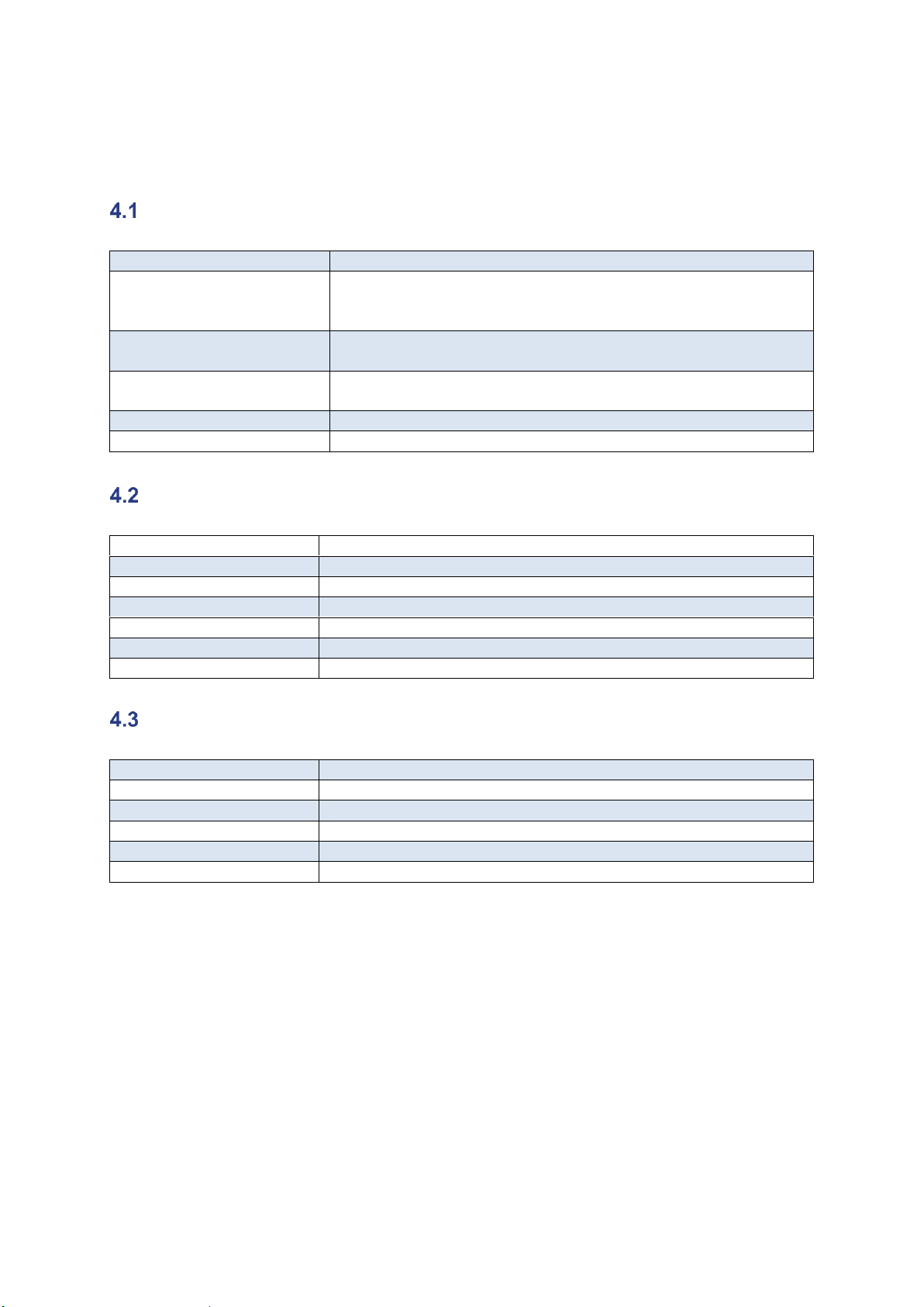
Head unit
Structure material
Titanium
Field camera adjustment
range
Horizontal setting corresponds to 0°
+ 15° (upwards)
- 45° (downwards)
Eye-Cam adjustment
range
Freely adjustable via the "swan neck"
Head size adjustment
range
The test subject's head size can be freely set via a drawstring
stopper.
Voltage supply
12 V DC
Current consumption
Max. 650 mA
Field camera
Active image area
4614 µm x 3444 µm
Array size
8MP / 3296 x 2460 pixels
Pixel size
1.4 µm x 1.4 µm
S/N ratio
35.7 dB
Lens size
1/3.2" optical format
Resolution
1920 x 1080 @ 30 fps
Operating temperature
-10° to 40°
Eye camera
Sensor
¼"’ CCIQIII B/W camera
Effective image area
3.8(H) x 2.9(V) x 4.86(D)
Effective pixels
640 x 240 (NTSC)
Pixel size
6µm x 6µm
Lens
3.9 mm / F2.8
Operating temperature
- 10° to 40°

Manual
18
Dikablis Eye Tracking Glasses Professional
Infrared LED
The Dikablis eye tracking system uses an infra-red light source to illu-
minate one or - in binocular applications - both eyes. To ensure eye
safety and to exclude any risk to the eyes, the IR-LED built into the de-
vice has been tested extensively by an independent laboratory in ac-
cordance with DIN EN 62471 ("Photobiological Safety of Lamps and
Lamp Systems") for the application scenario of eye tracking document-
ed here and classified as completely harmless in the standard's "risk-
free group".
All of the resulting measurement values from the IR-LED test are sev-
eral times below the threshold value set by the above standard for risk.
These critical threshold values are never reached at any point, which
means that the exposure time does not need to be limited either. As a
consequence, Dikablis is also suitable for long-term studies.
Ergoneers GmbH does everything possible to ensure the safety of
Dikablis users. And although the IR-LED used - as described above - is
classed as safe and harmless, everyone is different and perceives in-
fluences differently. If you should feel unexpectedly unwell, experience
headaches or other symptoms while using Dikablis, we advise stopping
its use and waiting 1 hour before using it again.
If the symptoms recur when you start using Dikablis again, please con-
tact Ergoneers GmbH without delay in order to check whether the prob-
lem is due to a technical defect or a general incompatibility with the sys-
tem.
Size
Flat top 2 x 2 mm
Opening angle
110°
IR emitter
875 nm TS AlGaAs, 17 mW/sr, 40 ns
IR detector
PIN Photodiode High Sensitivity Speed 7.5 ns
Current consumption
500 µA to 500 mA
Connector box
Video processing
2 channels + 2 monitoring channels
Video input
2 x CVBS 1Vpp 75 PAL (only via Ergoneers head unit)
Video output
2 x CVBS 1Vpp 75 PAL
Video monitoring output
2 x CVBS 1Vpp 75 PAL, optional
Primary
100 –240 V AC
Secondary
12 V 2.0 A DC
Table of contents
Popular Medical Equipment manuals by other brands


MIR
MIR Spirolab III Simplified operation guide

Medline
Medline HUDSON RCI Neptune ConchaSmart HUD42500 Instructions for use

Clarity
Clarity RetCam Shuttle User manual and service instructions

nubeca
nubeca PO8201 owner's manual

Chattanooga
Chattanooga Intelect Legend 2 Service manual

Helo
Helo LX Brief user's guide


