14 15
User manual - Infusion Thermo Bag User manual - Infusion Thermo Bag
Accessories and spare parts
CONTENT INSTALLATION KIT ARTICLE NUMBER 009122
Installation kit is supplied as an accessory and includes:
»Contact for wall mounting
»Switches for wall mounting
»Fuse holder with fuses
»Cables
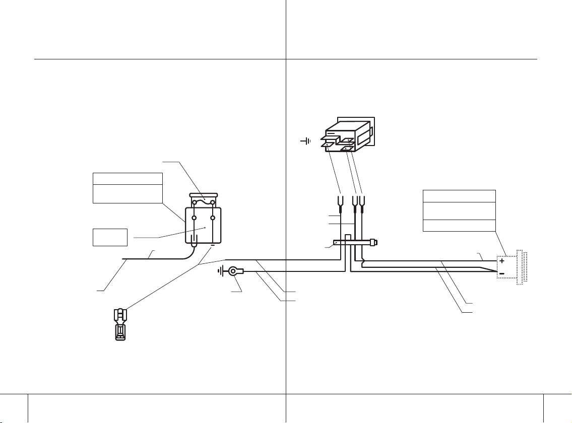
MOUNTING INSTRUCTION FOR INSTALLATION KIT
See gure 2 for mounting instruction.
Preparation
1. Mount the customised aluminium rail (article number 112012)
with a chassis knob in a suitable/desired location in the
ambulance. No more than 1.4 metres from the power source
which is limited by the cable length of 1.5 metres.
2. At a distance of max 60 cm from the bag, drill two round
holes with a diameter of 26 mm and 23 mm respectively in
the wall.
3. In the holes, the SELV contact and the switch included in the
Installation kit are mounted.
Electrical connection
1. From the switch, which is mounted in the smaller of the
pre-drilled holes, a separate supply cable with a cross-
sectional area of 2.5 mm2(attached cable) – with the pro-
duct as sole user – is drawn to the ambulance fuse holder
or directly to the battery in the engine compartment.
2. If the ambulance has a special battery for healthcare
equipment, the supply cable is drawn to this battery.
The connection must be made with good quality 6.3 mm
insulated cable shoe. For cars with 24 V DC, high quality
converters must be installed. The cable length in the bag
is 1.5 metres.
3. Connection must not be made to the car’s cigarette lighter
socket, as these usually cause large voltage drops after a
period of use.
OPERATIONAL CONTROL
When the unit is connected to the socket, the display should
be lit in red and the unit should start to heat up the infusion
solution. When the desired temperature of 37 ˚C ± 2 ˚C has
been reached, the display should light green.
If an external heat source is supplied and the temperature
of the liquid becomes warmer than specied, the display will
light in red. When the temperature drops, it will light green
again.