Adjusting Compensating Condensers in Model .200
The quality performance of this receiver depends to a great 5. Readjust the 3rd I. F. primary padder @ for maximum
output. Do not touch the grid padder @ again.
extent upon provid!ng a wide channel through the R. F. and
I. F. stages to permit the passage of a broad cast signal without
cutting of the side bands.
In order to produce this wide tuning band the set must be
carefullf _andaccu:ately adjusted. Th ese adjustments will be
m_orecriti cal than m the conventional radio, and the procedure
will be somewhat more complicated.
In making the adjustment;s, it is necessary to use an unmodu-
lated signal generator. The PHILCO Model 048 Set Tester
or.the Model 024 Signal Generator can be readily ada:pted for
th1~purpo se by the installation of a single-pole double-throw
switch,_and ~n add!tional grid lea~ resistor, as shown in Figure
4. This switch will adapt the signal generator for either a
modulated or an unmodulated signal.
Figure4 Adaplationof SignalGeneratorCircuitfor Use In MakingAdjustments
on Model200.
LocationsofAdjustingCondensers.
With an unmodulated signal, it is not possible to obtain an
indication of output by means of the usual form of output
meter. An indirect. indication can be obtained, however,
thr?ugh t~e automatw volume ~ontrol system by connecting
a high resistance voltmeter haVlng a scale reading of 0-5 or
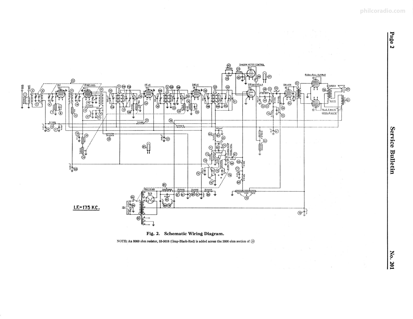
0-10 volts across the R. F. cathode resistor (i;, shown in the
wiring diagram Fig. 2. This connection can be made conven-
iently through the use of leads equipped with test clips. With
this arrangement, maximum output at the second detector
will be indicated by a minimum reading of the meter, and vice
versa. In other words, the action will be just the opposite of
an output meter used to measure audio frequency voltage at
the power output stage. With no signal applied to the receiver
the bias voltage indicated by the voltmete r, will be approxi~
mately 3 volts. This voltage will be redu ced by the application
of a signal to the R. F. or I. F. input circuits.
I. F. ADJUSTMENTS
After preparing the unmodul ated signal generator and con-
necting the voltmeter as directed, proceed as follows:
1. Set the receiver tuning dial at its extreme low frequency
position. Remove the grid clip from the cap of the 6-A-7
detector oscillator tube, and connect the signal generator
antenna lead in its place. Connect the ground lead from
the signal generator to the ground terminal of the chassis.
Adjust the signal generator frequency to exactly 175
K. C. Turn the fidelity control of the receiver all the way
to the left.
2. Adjust the 6 I. F. padd ing condensers @, @, @, @, @
and @ (see Fig. 5) in the tops of the 3 I. F. cans, for
maximum output (minimum meter reading), starting with
the compensato r or~padder at the front of the chassis, and
contin uing ;with the adjustments toward the rear of the
set. During these "adjustments, th e output of the signal
generato r should be regulated to maintain a voltmete r
3.
4.
reading of approximately 2 volts.
Connect a 250 Mmf. Condenser from the plate of the 2nd
I. F. tube to ground. This will increase the voltmete r
reading to approximately 2.5 volts.
Readjust the 3d I. F. secondary padder @ for maximum
output.
September, 1934
6.
7.
8.
1:urn the fidelity selectivity control all the way to the
right.
Adjust the 1st & 2nd I. F. tertiary padders @ and @ for
MINIMUM output (maximum voltmeter reading).
Lea:v!ng ~he ~delity selectivity control in the right hand
pos1t!on, tt will be found, upon varying the frequency of
the signal generator, that two definite dips will appear in
the voltmeter reading-one at 167 K. C. and another at
182 K. C. These dips in the voltmeter reading indicate
peaks in the tuning curve. The amplitude of these peaks
should ~e equal; that is, the same voltmeter reading should
b_eob~amed at both 167_K. C. and 182 K. C. Any varia-
t10ns m these two readmgs can be corrected by a slight
readjustment of the 3rd I. F. primary padder @. If the
peak at 167 K. C. is higher than the one at 182 K. C., the
primary padder will have to be turned out. If the reverse
is true, the capacity of this padder must be increased. In
a?)'. ~ase, the yoltmeter readings must be made equal by
d1v1dmgthe differences through readjustment .
.tl. F. ADJUSTMENTS.
The R. F. portion of the receiver is adjusted as follows:
9. Replace the grid clip on the detector-oscillator tube and
connect the antenna terminal of the signal generator to
the a~1;enna terminal of the chassis. Turn the fidelity
select1v1tycontrol all the way to the left and set the receiver
dial at 1,500 K. C. The same type of output indication
is employed as in the I. F. adjustments.
10. Adjust the signal generator for a frequency of 1500 K. C.
Adjust the "oscillator" padding condenser @ and the
"detector" padding condenser @ for maximum output
and in the order mentioned. Regula te the signal generator
output control to maintain a voltmeter reading of 2 volts
as before.
11. Turn in padder © (R. F.) until the voltmeter reads 2.5
volts and then adjust padder © (ANT.) for maximum
output.
12. Readjust padder © for maximum output . Do not touch
padder © again.
13. Set the receiver dial and the signal generator at 600 K. C.
Adjust the "oscillator low frequency " padder @ for maxi-
mum output. As the R. F. tuning is rather broad there
will be a considerable range on the dial that will give'about
the same output when the oscillator L. F. padder is adjusted
for maximum. The padder must be adjusted at the
middle of this range. This point may be determined with
accuracy in the following manner: Starting with the usual
voltmeter reading of 2 volts, slowly turn the receiver dial
toward the low frequency end and, at the same time,.
readju st the padder @ for maximum output until a point
is reached where the maximum output is indicated by a
voltmeter reading of 2.5 volts. Note carefully the exact
dial reading at this point. Follow the same procedure
while turning the dial in the opposite direction until the
outpu t reading decreases to the same value. Set the dial
at the exact center of these two points and readjust padder-
@ for maximum output.
14. Adjust the 3d I. F. tertiary padder @ to give mtnimum
width in the shadow tuning meter in the receiver. This·
padder is reached from rear of chassis.
ADJUSTMENT OF 10 K. C. FILTER
The 10 K. C. filter in the audio circuit will rarely require
readjustment. As the proper adjustment of this padder (@
on diagra m) requires an accurately calibrated audio oscillator ,
it should be reset only in the event that it has been tampered
with or in cases where it has become necessary to replace one
of the elements of this filter. An emergency adjustment of
this filter can be made in the following manner:
15. Connect the signal generator to the control grid of the type•
6-A-7 tube, leaving the grid clip in place,
16. Disconnect the voltmeter from resistor (i; and connect an
output meter to the plates of the power output tubes in
the usual way.
17. Set the receiver dial at 550 K. C. At this point, the oscil-
lator in the receiver will be tuned to 725 K. C. The
adjustment of the signal generator (switch in unmodulated
position) to approximately this same frequency will cause
an audible'.beat note"to'be heard in the speaker. By means
of the signal' generator tuning control,':reduce the fre-
quency of this beat not e until zero'beat is reached, at which
point the output meter reading will decrease to 0. Turn-
ing the receiver dial in either direction will gradua lly
increase the frequency of the audible note so that at 540
or 560 K. C. a 10.000 K. C. note will be heard. At either
of these points, the padder @) should be adjusted for·
minimum reading of the output meter.
Printed in U. S. A.